Diagram library
Every technical drawing on SafetyOrbit in one place — the arrangement of equipment, the direction of loads and the geometry that decides whether a system works. Each one links to the note it explains.
572 diagrams
Licensing. Training providers, equipment distributors and consultants can license these drawings for their own course material, toolbox talks and method statements. Employer plans include an internal-use licence.
Working at height and fall protection284Rope access80Lifting and rigging35Confined space16Machinery and isolation31Electrical12Excavation and groundwork2PPE and health43Vehicles and plant13Agriculture3Other subjects53
Working at height and fall protection 284
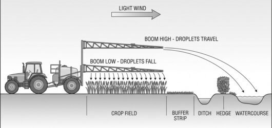 A sprayer working a field with the boom at two heights shown in comparison, droplets falling steeply from the Spray Drift, Re-Entry and the Tractor Cab
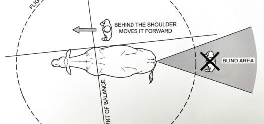 A plan view of an animal with a dashed flight zone circle around it, a line marked across its shoulder as the Working Around Cattle: Flight Zone and Handl
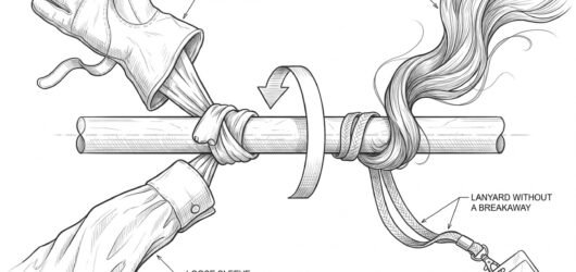 A rotating shaft with four items being drawn in and wound around it – a glove cuff, a shirt sleeve, long hair Entanglement: Clothing, Gloves, Hair and Jew
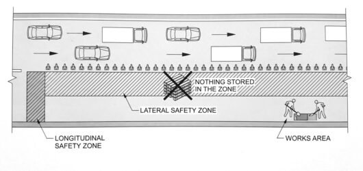 A plan view of a lane closure with the lateral safety zone hatched alongside the works and the longitudinal saThe Safety Zone: Working Clearance From Live
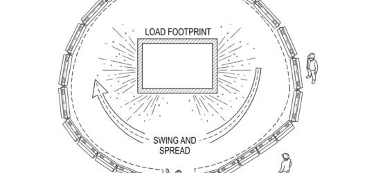 A plan view of a lift with the load footprint, a wider dashed exclusion boundary marked by barriers, the swingExclusion Zones and Why Nobody Stands Under
 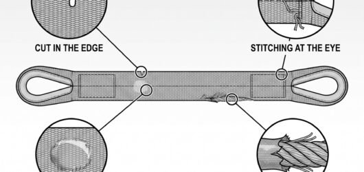 A webbing sling laid out flat with detail circles on a cut edge, pulled stitching at the eye, a heat-glazed paPre-Use Inspection of Textile Slings
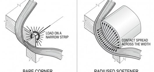 A webbing sling shown over a sharp corner with the load concentrated on a narrow strip, beside the same cornerProtecting Slings From Edges and Corners
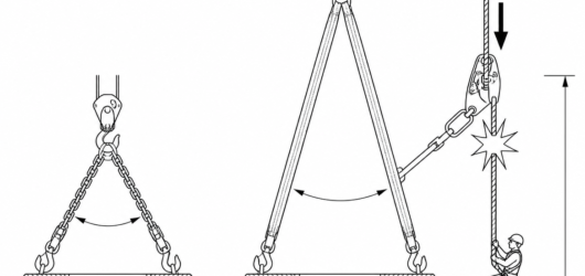
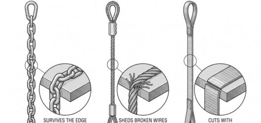 Three slings shown side by side – chain, wire rope and textile webbing – each with a detail of how it behaves Selecting a Sling: Chain, Wire Rope or Texti
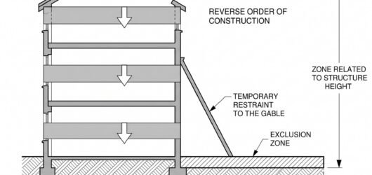 Section through a building showing the demolition sequence numbered from the roof downward, with a detail circDemolition Sequence Planning and Structural
 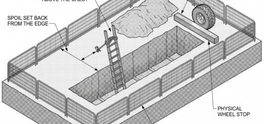 Plan and section of an open trench showing barriers around the full perimeter, a secured ladder extending abovSafe Access, Edge Protection and Spoil Place
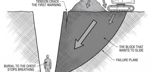 Section through a trench showing a tension crack behind the crest, a failure plane through the face, spoil staWhen an Excavation Needs Support: Assessing
 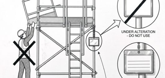 A scaffold access point with a tag holder shown enlarged, displaying the prohibition and permitted states, besScaffold Handover, Tagging and Who May Alter
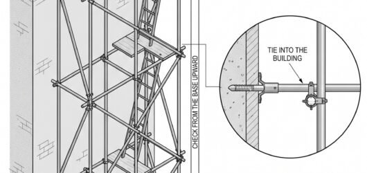 An elevation of a scaffold bay with detail circles on the base plate and sole board, a tie into the building, Scaffold Inspection Before You Step On It: W
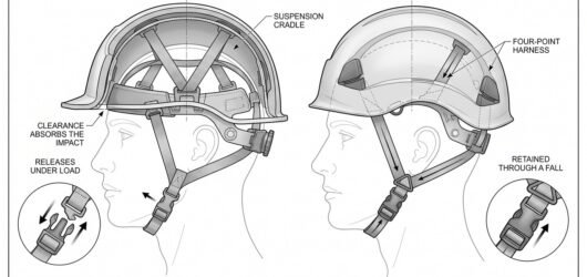 Cutaway comparison of an industrial safety helmet and a mountaineering-style helmet, showing the releasing chiSelecting a Safety Helmet for Construction W
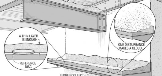 Simple line-art illustration of a settled dust layer on a horizontal overhead beam and ledge inside an industrHousekeeping and Combustible Dust Control
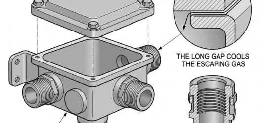 Simple line-art illustration of an ATEX-rated junction box with a flameproof enclosure and threaded cable glanSelecting ATEX-Rated Electrical Equipment
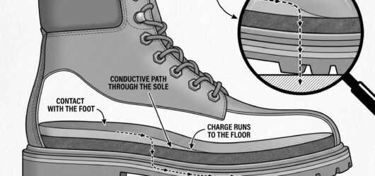 Simple line-art illustration of a safety boot with a visible conductive sole layer shown at a cutaway edge.Antistatic and ESD-Safe Footwear for Hazardo
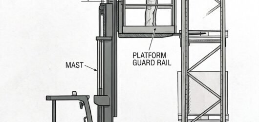 Simple line-art illustration of an order picker operator wearing a harness connected to an anchor point on thePicking at Height and Order Picker Safety
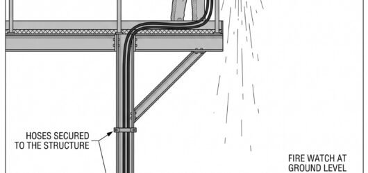 Simple line-art illustration of a welder working from an elevated platform with a hose routed up from ground-lWelding and Hot Work at Height
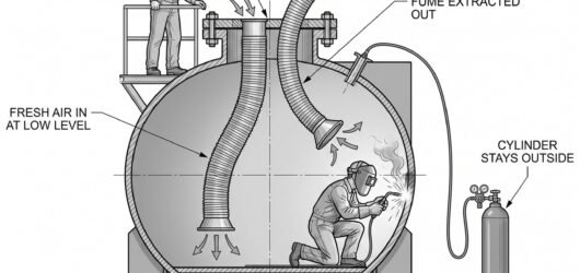 Simple line-art illustration of a ventilation duct and hose running into a confined space entry hatch, with a Confined Space Hot Work
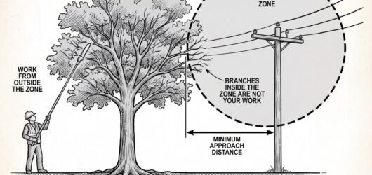 Simple line-art illustration of a tree growing near an overhead power line, with a clearance boundary marked bWorking Near Overhead Lines During Tree Work
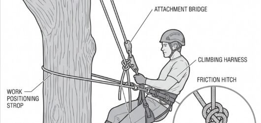 Simple line-art illustration of an arborist harness with a climbing rope routed through a friction hitch and cAerial Tree Work: Rope and Harness Systems f
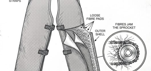 Simple line-art illustration of a pair of chainsaw protective leg chaps with layered fabric panels visible at Chainsaw Protective Clothing: Selecting Chap
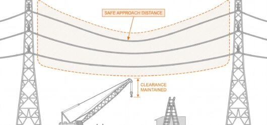 Elevation diagram of two transmission pylons carrying overhead conductors, with a hatched exclusion envelope dWorking Near Overhead Power Lines: Safe Appr
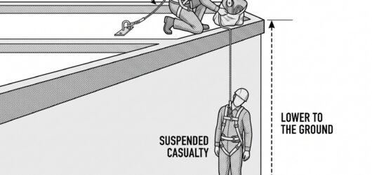 Diagram of a rescue scenario at a roof edge: a suspended worker connected to fall-arrest equipment, a rescuer Rescue Planning for a Fall Arrested by a Roo
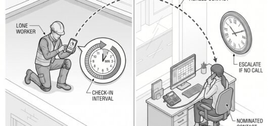 Diagram of a lone worker on a roof with a mobile device showing a check-in timer, connected to a ground-based Lone Working on a Roof: What Changes
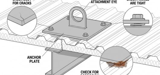 Diagram of a roof anchor pre-use inspection showing checks at three points: the anchor body for cracks or corrInspecting and Maintaining Roof-Mounted Anch
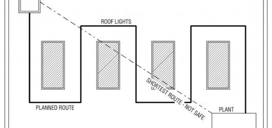 Diagram of a roof plan view showing a planned access route marked with a solid line running well clear of a roRoof Access Route Planning: Hatches and Skyl
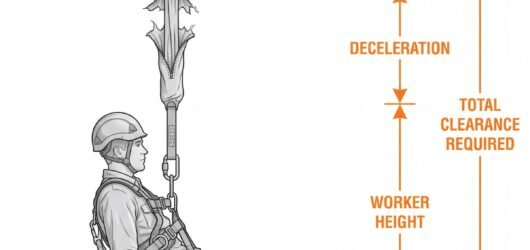 Diagram showing the components of a fall clearance calculation stacked vertically below a roof anchor: free faCalculating Fall Clearance for Roof-Mounted
 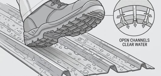 Diagram of a safety boot sole showing a slip-resistant tread pattern in contact with a wet metal roof surface,Footwear for Roof Work: Slip Resistance and
 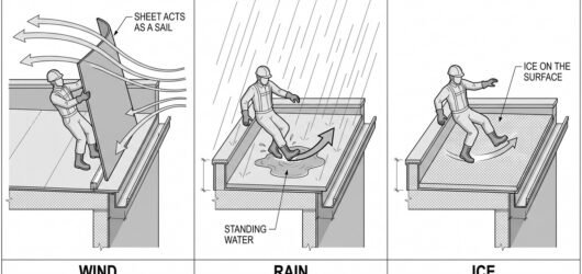 Diagram showing three weather hazard scenarios on a roof: gusting wind catching a large sheet material, rain cWeather Limits for Roof Work: Wind, Rain and
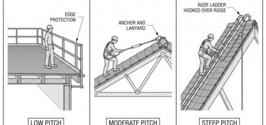 Diagram showing three roof pitch categories side by side: a flat roof with perimeter guardrails only, a moderaRoof Pitch and Choosing the Right Fall Prote
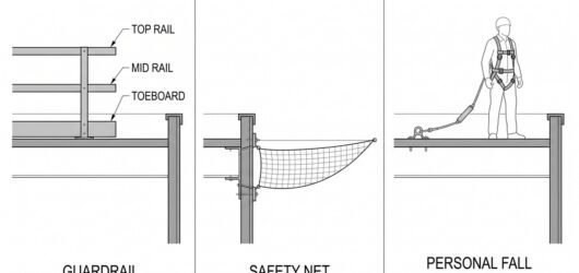 Diagram comparing three roof edge protection methods side by side: a guardrail system with top rail, mid rail Edge Protection Systems: Guardrails, Netting
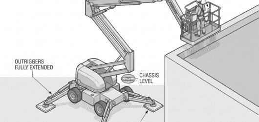 Diagram of a mobile elevated work platform set up on level ground with outriggers deployed on load-spreading pSafe Use of Mobile Elevated Work Platforms f
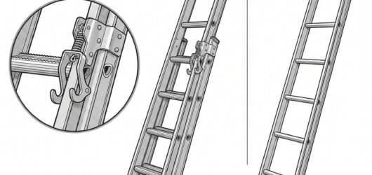 Diagram comparing a professional-rated extension ladder with reinforced stiles and rung locks against a lighteChoosing a Ladder Class for Roof Access: EN
 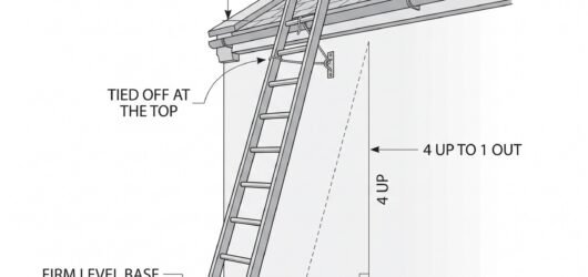 Diagram of a ladder set at the correct 4:1 angle against a wall, with the top tied off above the roof edge andLadder Safety for Roof Access: The Three-Poi
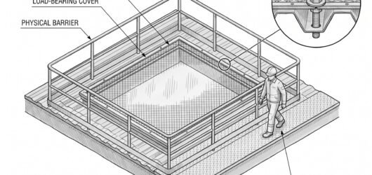 Diagram of a roof surface showing a fragile roof light panel with a warning border and physical barrier aroundWorking Near Fragile Roof Surfaces and Roof
 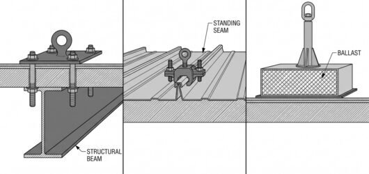 Diagram comparing three roof anchor types: a fixed anchor plate bolted into a structural beam, a temporary strSelecting a Roof Anchor System: Fixed, Tempo
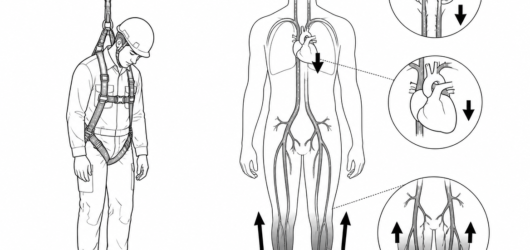 Immobile vertical suspension: blood pools in the legs and pelvis while venous return, cardiac output and cerebSuspension Trauma: Why Minutes Matter
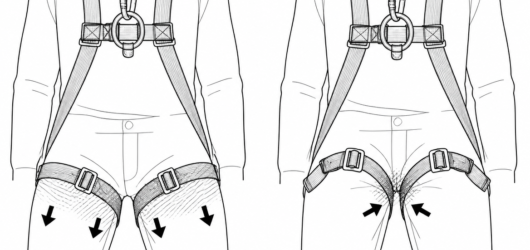 Left, correct: thigh straps snug and load spread across the thigh. Right, incorrect: slack straps let the harnSuspension Trauma: Why Minutes Matter
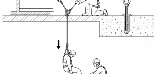 Rescue from above using a pre-rigged anchor and a lowering device: the goal is to bring the casualty to a leveSuspension Trauma: Why Minutes Matter
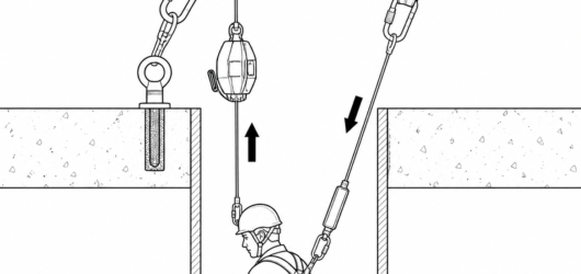 Two lines, two functions: a retrieval line to the lifting device and an independent backup fall arrest line onVertical Extraction from a Confined Space: R
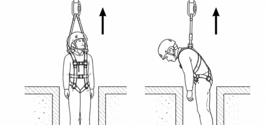 Correct: lifting from the shoulder rescue attachment points of an EN 1497 harness keeps the casualty upright aVertical Extraction from a Confined Space: R
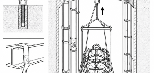 A packaged lift is wider and longer than a harness lift: check the stretcher, spreader bar and bridle against Vertical Extraction from a Confined Space: R
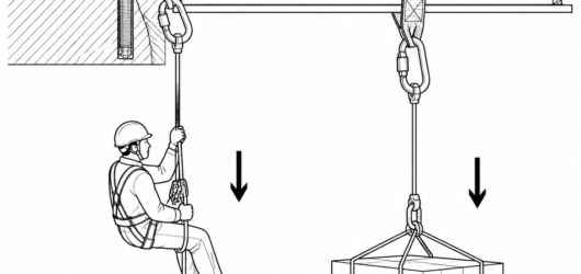
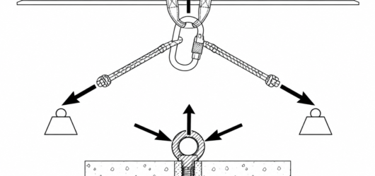 A 180° redirect at the anchor roughly doubles the force: 250 kg (≈2.45 kN) becomes about 5 kN at the anchor poHeavy Load Lowering Anchor: Rigging and Cont
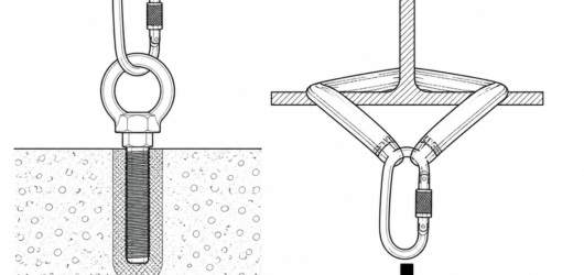 Keep the included angle at or below 90°: at 120° each leg already carries the full load, and at 150° it carrieHeavy Load Lowering Anchor: Rigging and Cont
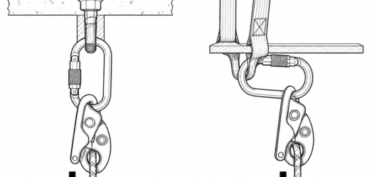
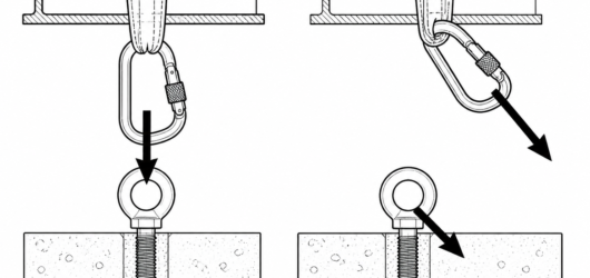 Correct: loaded along the spine, gate closed and locked. Incorrect: cross-loaded and gate pressed on an edge —Heavy Load Lowering Anchor: Rigging and Cont
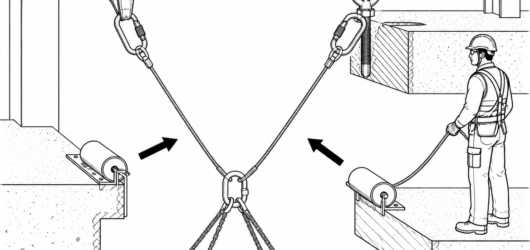 Two independent systems on separate anchors, each rated for the full load, with roller edge protection and a dHeavy Load Lowering Anchor: Rigging and Cont
 Correct: roller edge protection maintains a large bend radius. Incorrect: an unprotected arris abrades and comHeavy Load Lowering Anchor: Rigging and Cont
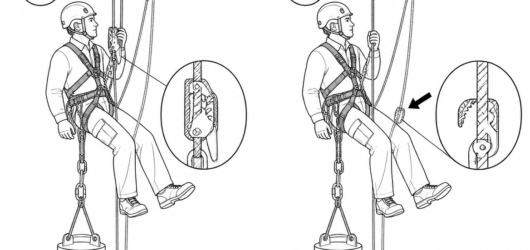
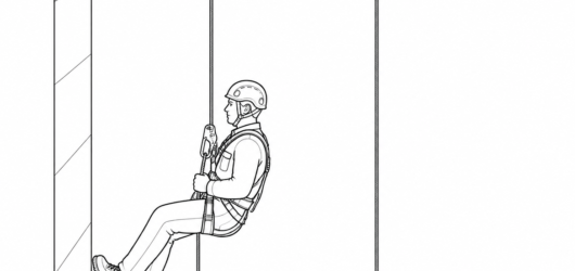 Two separately anchored ropes: the casualty stays held on one system while the other line and anchor remain avRelease and Rescue from a Static Rope: Load
 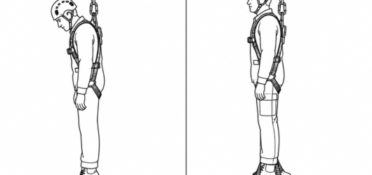 A conscious casualty who can stand in foot loops relieves leg-strap pressure and buys the rescue team time.Release and Rescue from a Static Rope: Load
 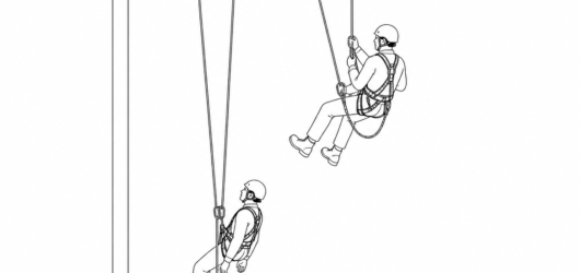 Correct: the rescuer descends on an anchor and rope independent of the casualty's, with a separate back-up linRelease and Rescue from a Static Rope: Load
 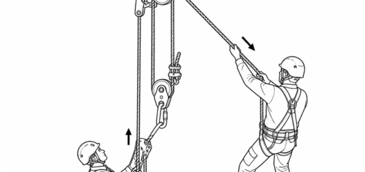 Only a few centimetres of lift is needed: with the progress capture holding, the jammed cam or locked descendeRelease and Rescue from a Static Rope: Load
 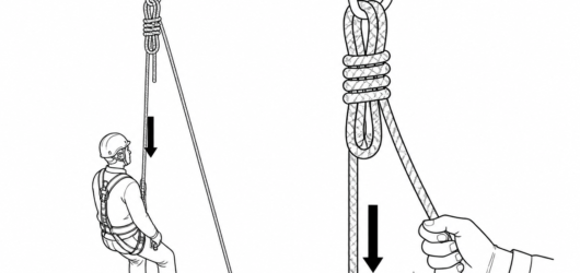 Rigged before work starts: a tie-off that can be released under load removes the need to lift the casualty at Release and Rescue from a Static Rope: Load
 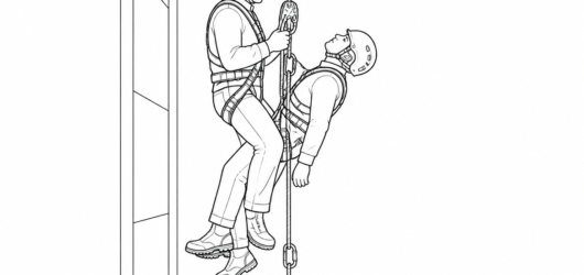 Two-person load on one descender: keep the connection short, add friction rather than grip, and keep the airwaRelease and Rescue from a Static Rope: Load
 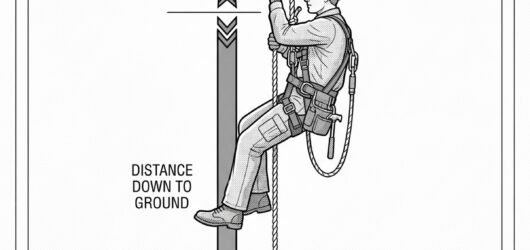 Side-view diagram of a worker suspended mid-span on a long rope, with arrows comparing the distance down to thRelease and Rescue from a Long Rope: Getting
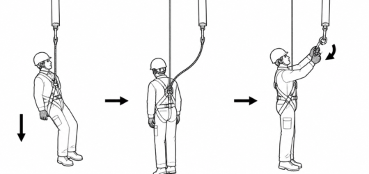 A loaded fall arrester or backup device can only be opened after the weight is fully carried by an independentRelease and Rescue from a Long Rope: Getting
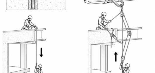 Lowering works with gravity and needs less force; raising needs pulleys, progress capture and anchors rated foRelease and Rescue from a Long Rope: Getting
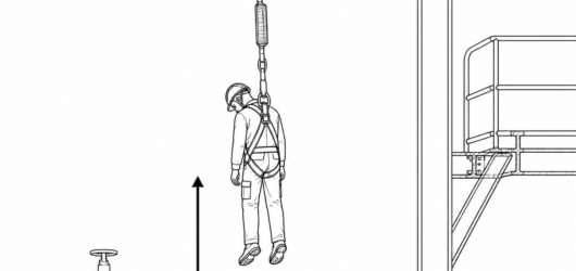
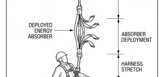
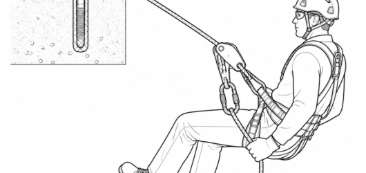
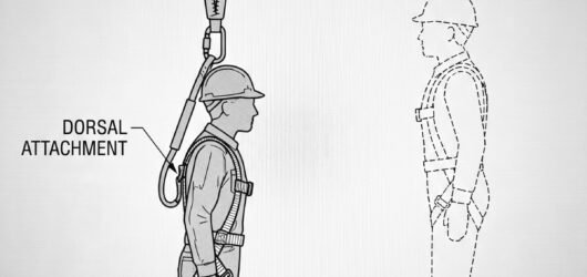 Side-view diagram of a worker suspended from an arrested fall: overhead beam anchor, fully deployed energy absRelease and Rescue from a Fall-Arrest System
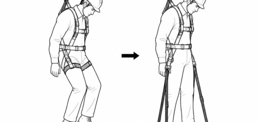 Left: unsupported legs, leg straps loaded across the thighs. Right: relief straps deployed as a stirrup so theRelease and Rescue from a Fall-Arrest System
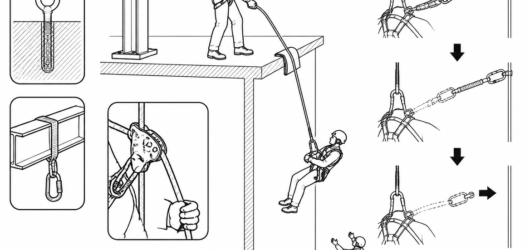 Controlled lowering with a descender to EN 341: rescuer on an independent anchor, edge protection under the roRelease and Rescue from a Fall-Arrest System
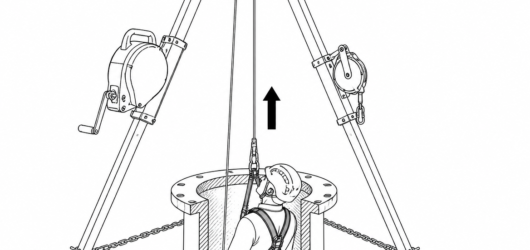 Where there is no clear space below, the casualty is raised: a retractable device with an integrated retrievalRelease and Rescue from a Fall-Arrest System
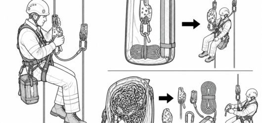 A rescue kit pre-rigged with the descender already installed on the rope and edge protection included beats a Release and Rescue from a Fall-Arrest System
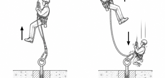
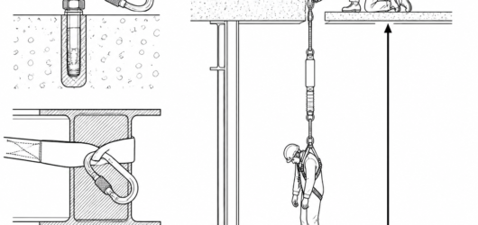 A deployed absorber extends the assembly; EN 354 caps the total lanyard, absorber and connector length at 2 m,Rescuing a Person Hanging on an Energy Absor
 Assess the space below before choosing a method: deployment has already consumed clearance and may have broughRescuing a Person Hanging on an Energy Absor
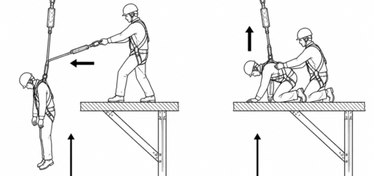 Approach from the side and support the casualty fully on the platform before disconnecting the fall arrest lanRescuing a Person Hanging on an Energy Absor
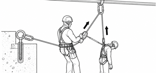 The arrested worker is suspended and immobile; the rescuer works from a separate, independent anchor rather thRelease and Rescue of a Co-Worker Using a Re
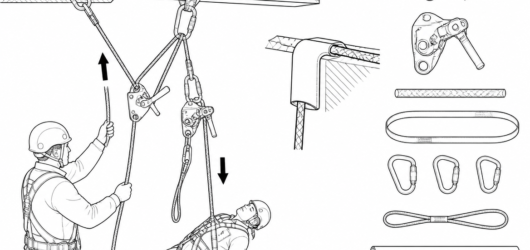 A typical kit: EN 341 descender, EN 1496 lifting device, EN 1891 Type A rope, EN 795 anchor sling, EN 362 connRelease and Rescue of a Co-Worker Using a Re
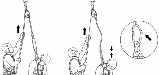 Raise the casualty only a few centimetres: the arrested lanyard must go visibly slack before its connector canRelease and Rescue of a Co-Worker Using a Re
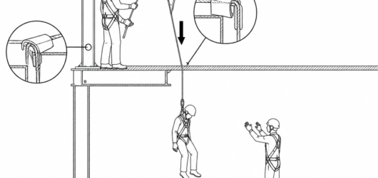 Protect the rope at every hard edge and confirm a clear landing zone with a receiver on the lower level beforeRelease and Rescue of a Co-Worker Using a Re
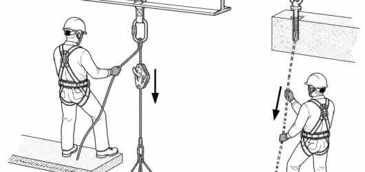 Working line (solid) on the descender at the anchor; the safety line (dashed) is on an independent anchor withHauling: Building a Combined Lowering and Ra
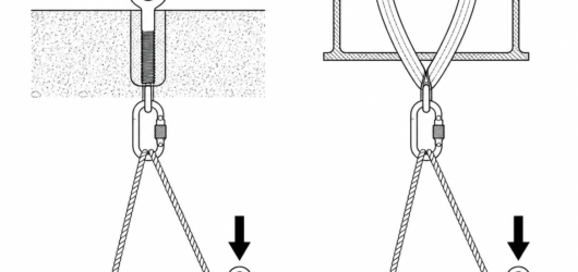 Arrow thickness shows relative force: in both configurations the anchor carries the load plus the haul force, Hauling: Building a Combined Lowering and Ra
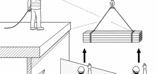 The edge attendant is the only person who can see the load and the edge, and holds an unconditional stop call.Hauling: Building a Combined Lowering and Ra
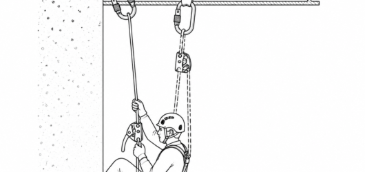 Two independent lines: the solid working line carries the load through the descender; the dashed safety line iAccompanied Descent with a Rope Grab: Riggin
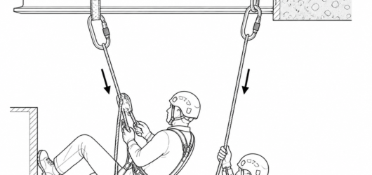 Working line and safety line on independent anchors, each verified for a multi-person load under EN 795:2012 aAccompanied Descent with a Rope Grab: Riggin
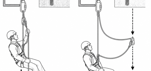 Left, correct: grab kept high with the manufacturer's short lanyard. Right, incorrect: accumulated slack increAccompanied Descent with a Rope Grab: Riggin
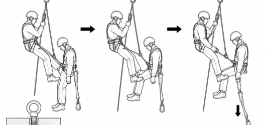 The casualty is linked short, kept upright with the thighs supported, and their own loaded lanyard is releasedAccompanied Descent with a Rope Grab: Riggin
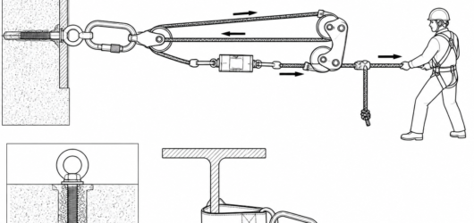
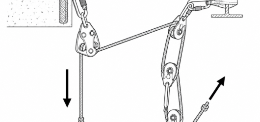 Typical layout: the descender at the anchor holds and lowers, while a 3:1 built on the free strand does the raHaul System with a Descender: Rigging, Limit
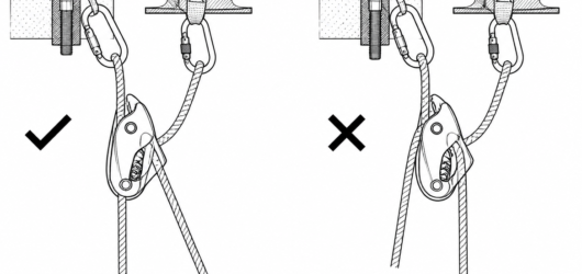 Correct: rope threaded per the manufacturer's diagram, load strand to the anchor side. Incorrect: reversed thrHaul System with a Descender: Rigging, Limit
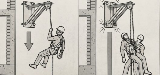 Comparison diagram showing a single-person load on an anchor versus the roughly doubled load of a rescuer and Accompanied Descent Rescue: How the Manoeuvr
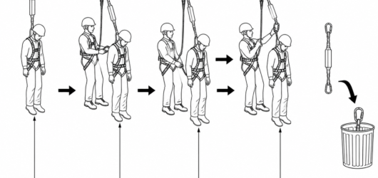 Disconnect the casualty's original lanyard only once the transfer is complete and the slack is visible; a deplAccompanied Descent Rescue: How the Manoeuvr
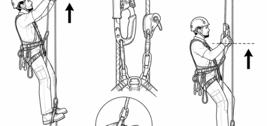 Calibration check: at full extension the handled ascender should sit around forehead height with straight armsGreater Efficiency on Rope Ascents: Techniqu
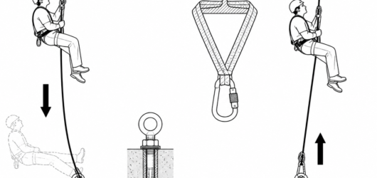 Tensioning the lower end at a rated anchor stops the rope absorbing stroke length — use a rated anchor point pGreater Efficiency on Rope Ascents: Techniqu
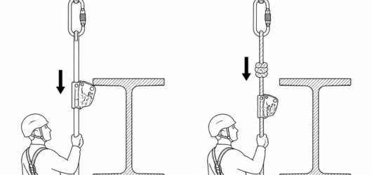 Left: rigid anchor line to EN 353-1 — the device passes the bracket, attachment is never broken. Right: flexibApproaching an Obstacle with a Rope Grab: Ho
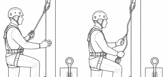 Correct: device at chest height, connector taut, hands on the structure. Incorrect: low device, slack above itApproaching an Obstacle with a Rope Grab: Ho
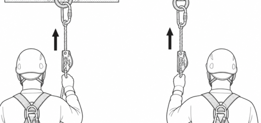 Correct: device oriented upward toward the anchor, connected only to the sternal or dorsal fall arrest attachmFunction Testing a Rope Grab Every Time It's
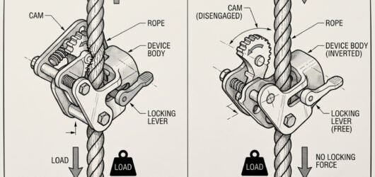 Comparison showing a correctly oriented rope grab locking on the anchor line versus the same device fitted upsFunction Testing a Rope Grab Every Time It's
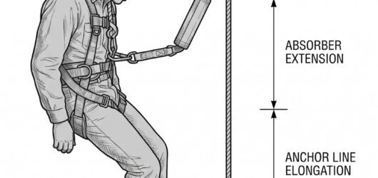 Elevation diagram of required fall clearance below a worker on a guided type fall arrester, showing the stackeFunction Testing a Rope Grab Every Time It's
 The load travels on its own independently anchored line — never on the working line or the safety line of a suUsing PPE for Material Handling: Ground-Leve
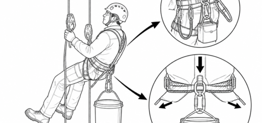 Gear loops are for carrying light equipment only; heavy loads clipped to the suspension attachment can push thUsing PPE for Material Handling: Ground-Leve
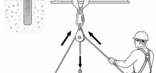 The anchor at a redirect or pulley can see a resultant force greater than the load weight; pulley working loadUsing PPE for Material Handling: Ground-Leve
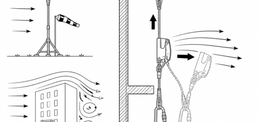
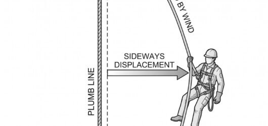 Side-view diagram comparing a plumb anchor line (dashed) with the same line bowed downwind (solid), showing thRope Grab Behaviour in High Winds: What Chan
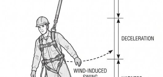 Stacked clearance diagram showing the components of required fall clearance below the user – free fall, deceleRope Grab Behaviour in High Winds: What Chan
 Take the anemometer reading at the work position: ground-level and forecast figures understate wind at height Rope Grab Behaviour in High Winds: What Chan
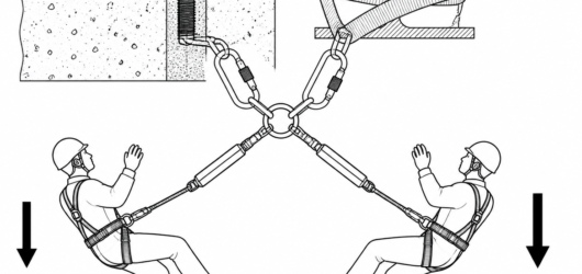 Two simultaneous fall arrests load the anchor and its structural fixing together — EN 795:2012 testing assumesAnchoring Two People to One Point: When a Sh
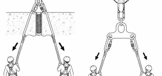 Left, incorrect: two connectors stacked in one eye, loaded across the minor axis and against the gate. Right, Anchoring Two People to One Point: When a Sh
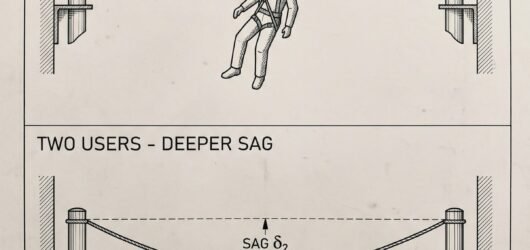 Elevation diagram of a horizontal flexible anchor line showing deeper cable sag and greater required fall cleaAnchoring Two People to One Point: When a Sh
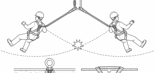 Two users on one point work on converging radii — their swing arcs can intersect, so one arrest can drag or stAnchoring Two People to One Point: When a Sh
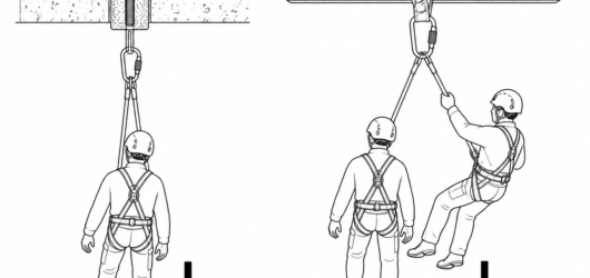 Rescue adds a further load to an anchor that is already holding a suspended person — verify or designate a sepAnchoring Two People to One Point: When a Sh
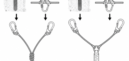 A Y-lanyard is not a shape: the certified version (right) has one EN 355 energy absorber shared by both tails,Y-Lanyard from a Knotted Sling: Why the Impr
 Failure starts at the bend: knots concentrate load on the outer fibres and reduce strength by an amount you caY-Lanyard from a Knotted Sling: Why the Impr
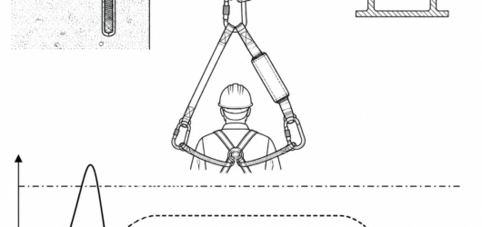 The dash-dot line is the 6 kN arrest force limit set by EN 355; a static sling transmits the tall spike, an enY-Lanyard from a Knotted Sling: Why the Impr
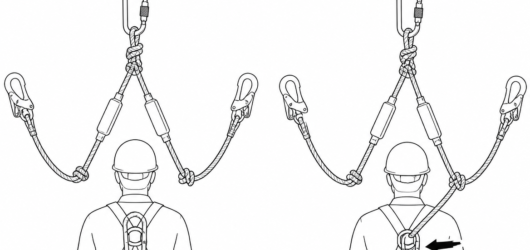 Correct: spare tail parked in the harness keeper. Incorrect: spare tail clipped to the fall arrest attachment,Y-Lanyard from a Knotted Sling: Why the Impr
 Vertical fall clearance stack diagram beneath an anchor point: dimension bars from top to bottom represent lanY-Lanyard from a Knotted Sling: Why the Impr
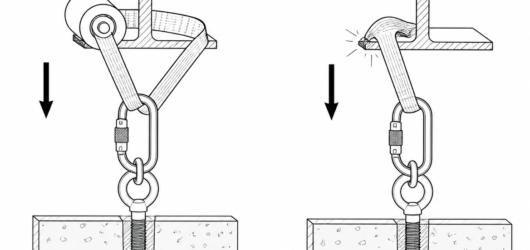
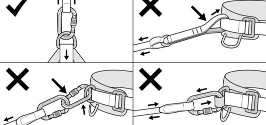
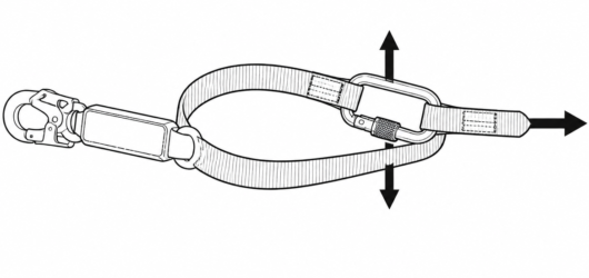 Incorrect: a standard EN 354 lanyard wrapped and clipped to its own webbing loads the connector across the gatUsing a Lanyard as a Temporary Anchor: When
 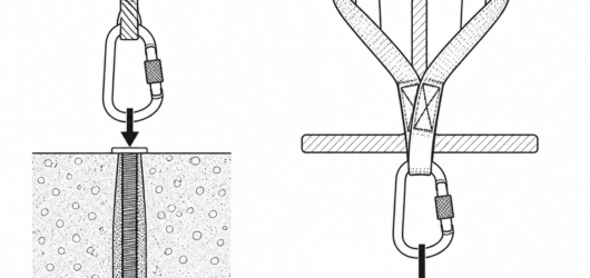 Correct: an EN 795 Type B anchor sling choked around the beam gives a rated metal attachment point, with the cUsing a Lanyard as a Temporary Anchor: When
 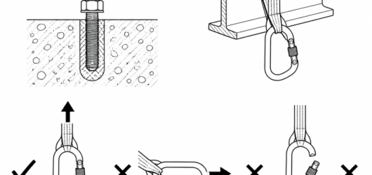 Connector ratings under EN 362 apply to the major axis with the gate closed and locked; sideways and gate-openUsing a Lanyard as a Temporary Anchor: When
 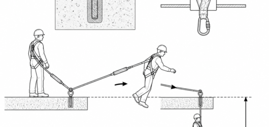 Anchor height decides the fall factor: a foot-level attachment with a 2 m lanyard creates a factor 2 fall thatUsing a Lanyard as a Temporary Anchor: When
 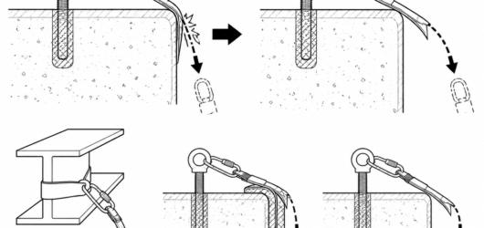 If the line can contact an edge in a fall, use equipment approved for that edge radius, protect the edge, or mUsing a Lanyard as a Temporary Anchor: When
 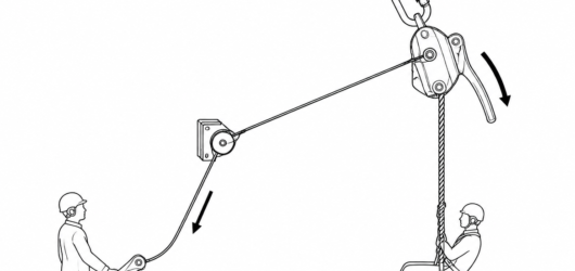 Configuration A: descender at the anchor, load on the rope, handle actuated by a cord from a ground operator —Remote Control of a Descender Handle with a
 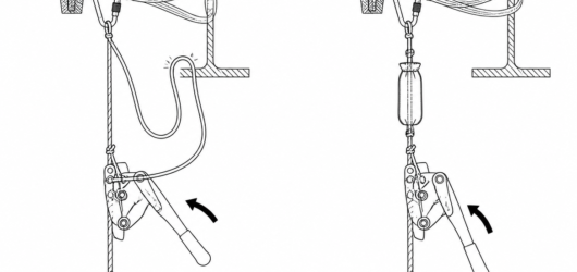 Incorrect: a slack cord loop caught on structure holds the handle open and the load runs. Correct: short, tensRemote Control of a Descender Handle with a
 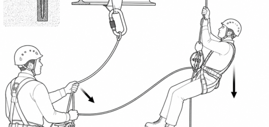 Correct: belay line on an anchor independent of the main line, brake strand controlled by hand, slack kept to Belaying with a Winch-Descender: Rigging, Sl
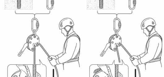 Left, correct: load strand enters on the load side and engages the cam. Right, incorrect: reversed threading, Belaying with a Winch-Descender: Rigging, Sl
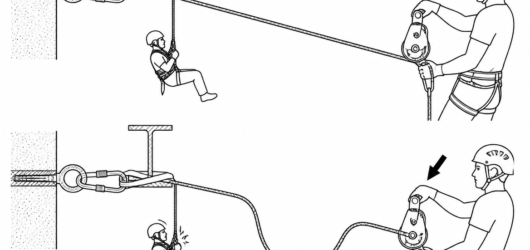 Top, correct: belay line taken in with the raise. Bottom, incorrect: a hanging loop of slack shock-loads a lowBelaying with a Winch-Descender: Rigging, Sl
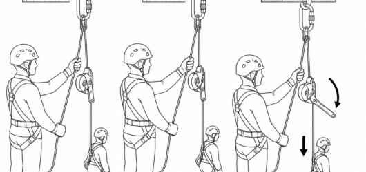 Hold, assess, then lower: the brake hand stays on the free strand throughout, including while the handle is opBelaying with a Winch-Descender: Rigging, Sl
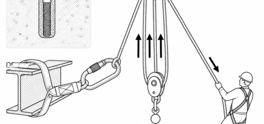 Simple 3:1 (Z-rig): three strands act on the travelling side, so TMA is 3:1 — the anchor pulley itself adds noHow to Calculate Mechanical Advantage: Stran
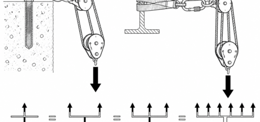 Compound 2:1 on 3:1 = 6:1; arrow thickness shows tension multiplying stage by stage, verified with the T-methoHow to Calculate Mechanical Advantage: Stran
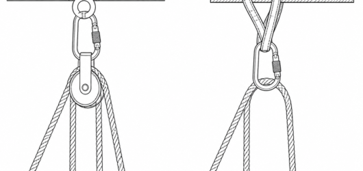 Left: rope on a bearing pulley, typically around 95% efficient. Right: rope over a carabiner, typically 50–60%How to Calculate Mechanical Advantage: Stran
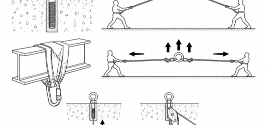 The anchor sees the resultant of every strand on it — narrow angles approach the sum of the tensions, and the How to Calculate Mechanical Advantage: Stran
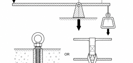 Lever MA = effort arm ÷ load arm; a 1.05 m effort arm over a 0.15 m load arm gives 7:1, and the fulcrum carrieHow to Calculate Mechanical Advantage: Stran
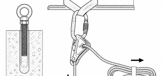 The four parts that make an anchor releasable: verified structural point, rated anchor connection, correctly oRigging a Releasable Anchor with a Descender
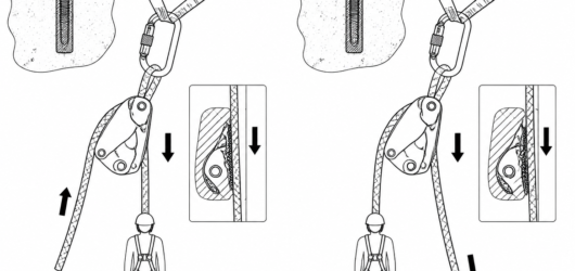 Correct: rope routed per the device pictogram so the cam engages under load. Incorrect: load and free sides reRigging a Releasable Anchor with a Descender
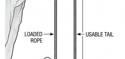 Elevation diagram showing that the distance a load can be lowered from a releasable anchor equals the usable rRigging a Releasable Anchor with a Descender
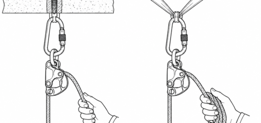 Added friction on the free side gives control with heavier and rescue loads — only in configurations the manufRigging a Releasable Anchor with a Descender
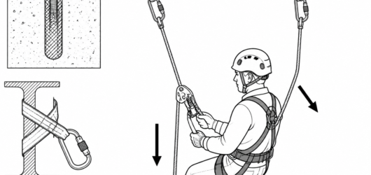
 Correct: locking connector loaded along the major axis, gate closed and clear of the structure. Incorrect: croRigging a Releasable Anchor with a Descender
 The two-rope principle of EN ISO 22846-2 still applies: independent anchors, and a backup line kept clear of tRigging a Releasable Anchor with a Descender
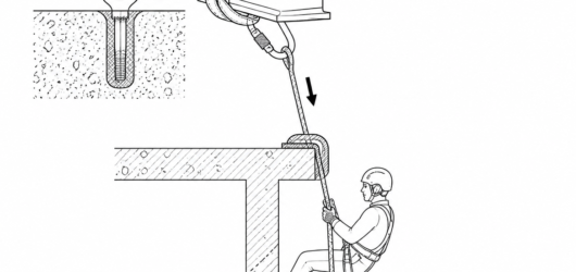 Fixed edge protection prevents abrasion on descent and stops the unloaded rope binding sideways during retrievRetrievable Rope Rigging: How to Set Up a Pu
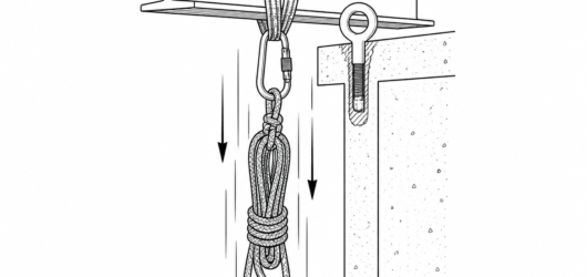 Retrieve from outside the fall line: the rope, its ends and all anchor hardware land under the anchor at speedRetrievable Rope Rigging: How to Set Up a Pu
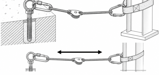
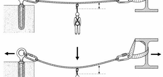 Less sag means more tension: at 2% sag each anchor sees roughly 12.5 times the suspended load, at 10% sag rougTyrolean Traverse Technique: Tension, Anchor
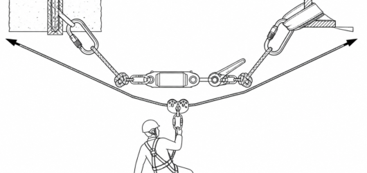 Both ends of a traverse carry the full rope tension: two independent anchor points, a narrow sling angle, an iTyrolean Traverse Technique: Tension, Anchor
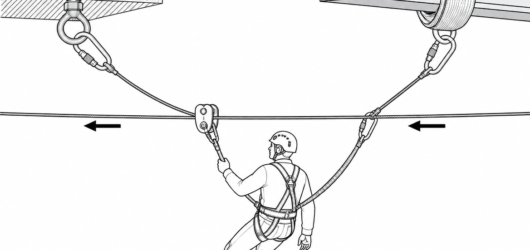 Two lines, two anchors: the working attachment is short and ventral into the trolley, and the backup rides an Tyrolean Traverse Technique: Tension, Anchor
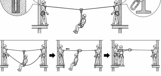 A person stalled at mid-span cannot usually self-rescue – the retrieval method, the release of tension and theTyrolean Traverse Technique: Tension, Anchor
 Pre-use checks target the specific defects a traverse produces: glazing and flat spots where rope crossed edgeTyrolean Traverse Technique: Tension, Anchor
 Line tension is set by geometry: T = W / (2 sin of the rope angle from horizontal, so a 1 kN load at 5% sag puTyrolean Tensioning: Managing Sag, Line Tens
 Incorrect (left): a visually flat line multiplies the load many times over. Correct (right): around 10% sag hoTyrolean Tensioning: Managing Sag, Line Tens
 A tensionless wrap avoids the strength loss of a knot; the back-up is anchored to a separate structural memberTyrolean Tensioning: Managing Sag, Line Tens
 A low-ratio 3:1 haul plus an inline load cell keeps tension both limited and measurable; progress capture holdTyrolean Tensioning: Managing Sag, Line Tens
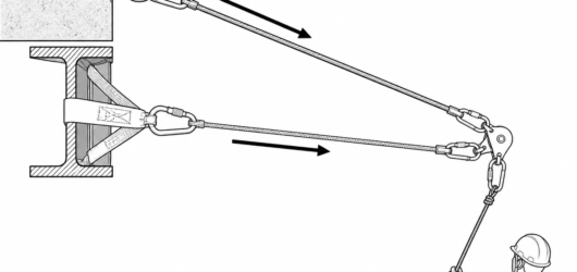 Correct: working line and separately anchored safety line, both connections locked and loaded along the major Tyrolean Tensioning: Managing Sag, Line Tens
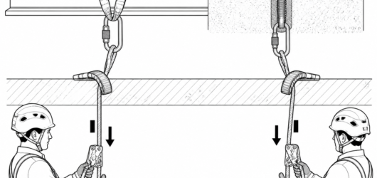 Correct dual-tension layout: independent anchors, one operator per device, and separate edge protection for eaLimiting Rope Stretch with Two Descenders: L
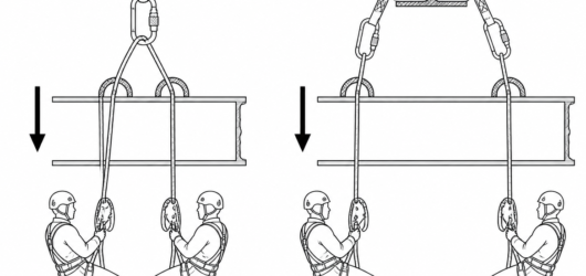 Incorrect (left): shared anchor and shared edge protection create a single failure point. Correct (right): fulLimiting Rope Stretch with Two Descenders: L
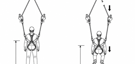 With both lines tensioned, a failure produces a short stretch-limited settle rather than a fall arrested by a Limiting Rope Stretch with Two Descenders: L
 A visible bow in one rope means that line is unloaded and the other is carrying the full load — the edge attenLimiting Rope Stretch with Two Descenders: L
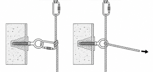 Re-belay (left): the rope terminates at the intermediate anchor and a separate lower section hangs from it. DeRe-Belay Ascent Technique: Passing an Interm
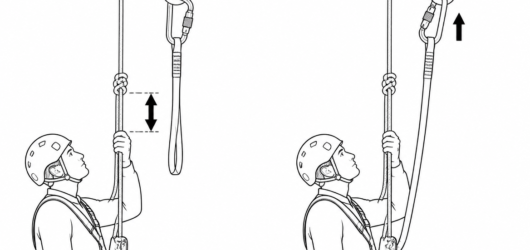 Step 1 and 2: stop roughly a hand's width below the anchor knot, then clip the short lanyard into the anchor pRe-Belay Ascent Technique: Passing an Interm
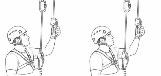 Mid-transfer: the handled ascender is established on the upper rope before the chest ascender is removed from Re-Belay Ascent Technique: Passing an Interm
 Correct (left): stay only as high above the anchor as the transfer requires. Incorrect (right): excess height Re-Belay Ascent Technique: Passing an Interm
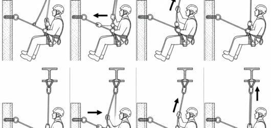 Working line and safety line are re-belayed on separate anchors and transferred one at a time; the back-up devRe-Belay Ascent Technique: Passing an Interm
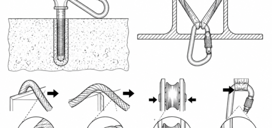
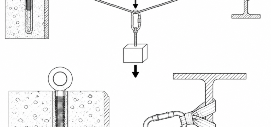
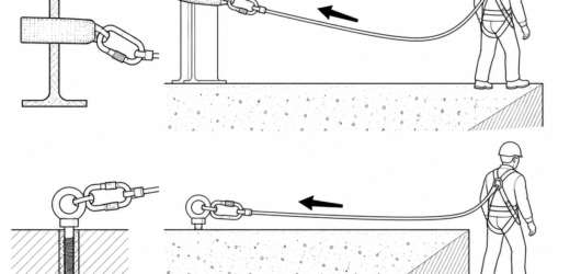
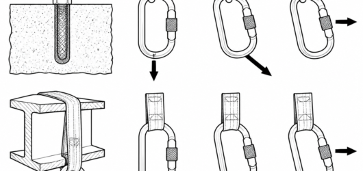
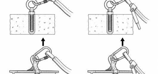
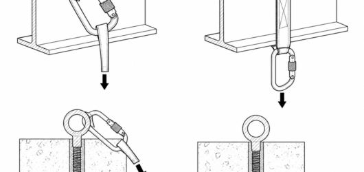 Incorrect: connector prised over a flange edge. Correct: rated anchor sling around the member, connector hangiExamples of Dangerous Connector Loading: How
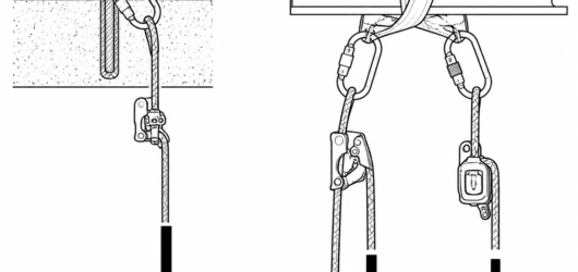 Incorrect (left): one clamp, one rope, one anchor – no second load path. Correct (right): working line with asUsing a Single Rope Clamp: Why Not?
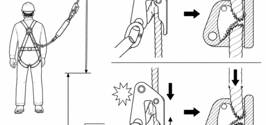 A toothed cam grips under progressive load but acts as a cutting edge under shock load – the reason EN 12841 tUsing a Single Rope Clamp: Why Not?
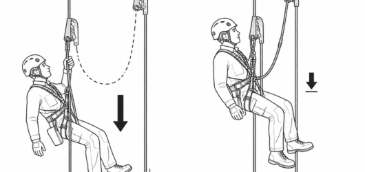 Slack defeats the second line: keep the backup device high and short so any fall on the safety line stays shorUsing a Single Rope Clamp: Why Not?
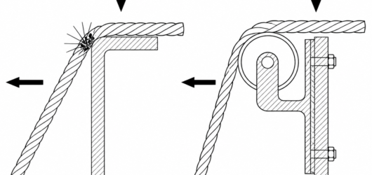 Left: load and lateral movement concentrated on a few sheath fibres at a small-radius corner. Right: an edge rWorking Near Sharp Edges and Hot Work: Sharp
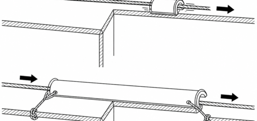 Incorrect: the protector travelled with the rope and the edge is exposed. Correct: the protector spans the whoWorking Near Sharp Edges and Hot Work: Sharp
 The first control is removal of contact: a deviation or higher, set-back anchor takes the line off the edge enWorking Near Sharp Edges and Hot Work: Sharp
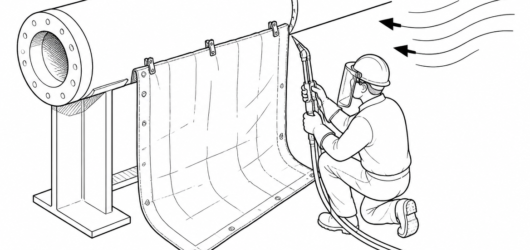 Positive separation: work below and to the side of the lines, shield the trajectory with a blanket, and accounWorking Near Sharp Edges and Hot Work: Sharp
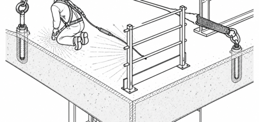 Working line and backup line on separate anchors and separate edge protection: one edge or one spark shower caWorking Near Sharp Edges and Hot Work: Sharp
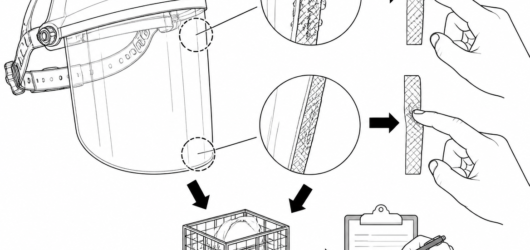 Inspect by touch as well as by eye: spatter damage feels hard and glassy, edge damage feels flat or soft. EithWorking Near Sharp Edges and Hot Work: Sharp
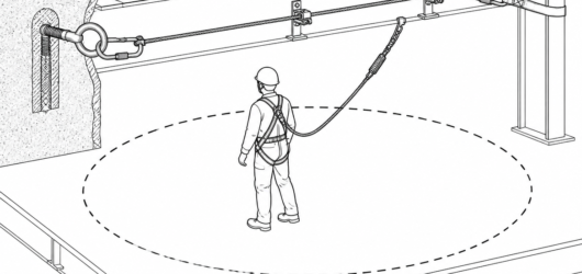 Line route defines the working zone: the user's reachable area is set by lanyard length and cable position, noHorizontal Life-Line Installation: Planning,
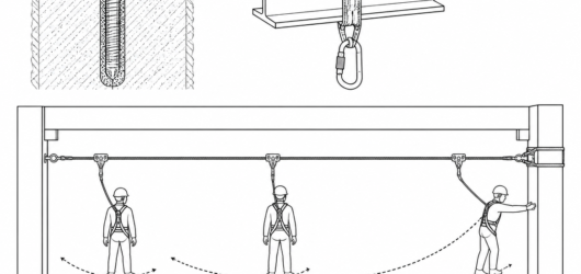 Swing fall is controlled by layout: the further a user works off the line, the longer the pendulum and the greHorizontal Life-Line Installation: Planning,
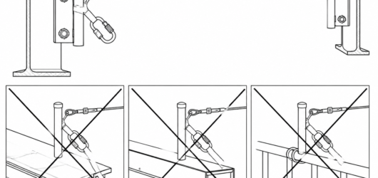 Correct: end post fixed into verified structural steel. Incorrect: gutters, edge trim and handrails are not anHorizontal Life-Line Installation: Planning,
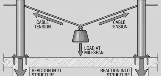 Force diagram showing a mass at mid-span of a near-horizontal life-line, with tension arrows along the cable aHorizontal Life-Line Installation: Planning,
 Pre-tension is set to the manufacturer's specified value using the supplied tension indicator, then re-checkedHorizontal Life-Line Installation: Planning,
 Cable deflection is added on top of the arrest distance figure quoted for a rigid anchor point — omitting it iHorizontal Life-Line Installation: Planning,
 Correct arrangement: two separately anchored lines – working line to the belt side points, safety line to the Work Positioning with a Rope Grab: Standards
 Keep the grab at or above the attachment point and the lanyard taut – work positioning equipment has no energyWork Positioning with a Rope Grab: Standards
 Right: added slings lengthen the connection, raising both fall distance and the shock load a toothed cam puts Work Positioning with a Rope Grab: Standards
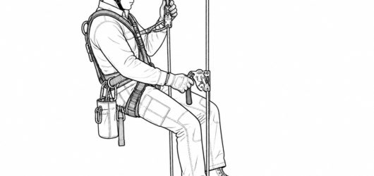 Starting configuration for a down-climb: working line with chest and handled ascenders, safety line with the bAscender Down-Climb: Losing a Short Distance
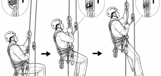 Correct: the safety-line device is advanced with every cycle and the connection kept short. Slack above the deLong or Short Rope Ascent: Choosing the Tech
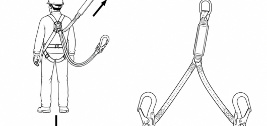 Twin-leg lanyard anatomy: one energy absorber, two arms — only one arm is meant to be loaded at a time.Lanyard Arm Parking: How to Stow the Unused
 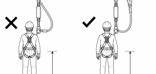 Incorrect: hooking the spare arm to the absorber short-circuits it, so arrest force is no longer limited to 6 Lanyard Arm Parking: How to Stow the Unused
 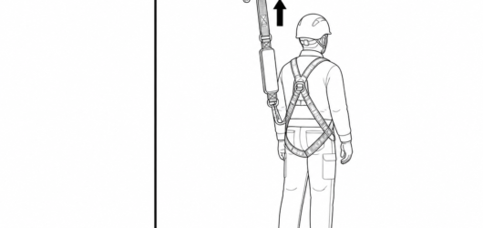 Correct: parked high on the dedicated keeper, gate closed, webbing routed clear of the energy absorber.Lanyard Arm Parking: How to Stow the Unused
 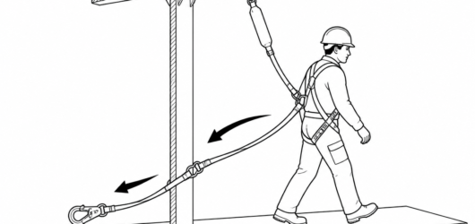 Incorrect: a dangling arm snags on structure, swings at knee height and trails across the walking surface.Lanyard Arm Parking: How to Stow the Unused
 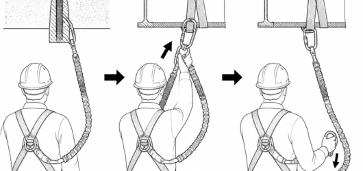 Transfer sequence: connect the parked arm to the next anchor, release the first arm, then park it immediately.Lanyard Arm Parking: How to Stow the Unused
 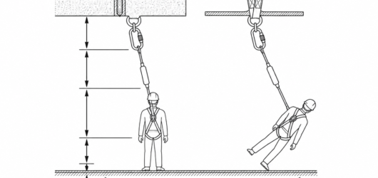 Each element of the clearance stack is measured below the anchor; the dashed arc shows the swing that must alsOblique Anchors and Fall Distance: How Later
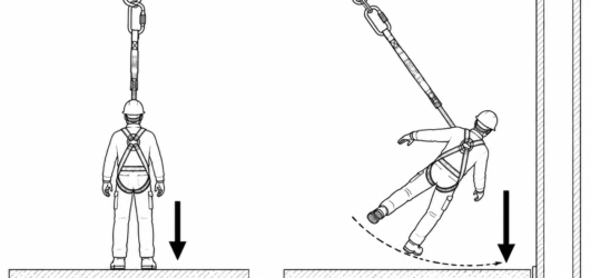 Left: anchor overhead, minimal pendulum. Right: the same equipment with a lateral offset swings the faller intOblique Anchors and Fall Distance: How Later
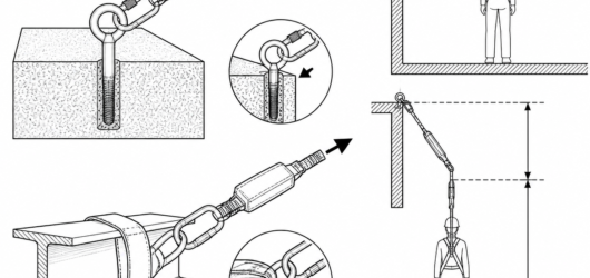 An obliquely loaded line concentrates contact on a short length of the arris and adds friction that can prevenOblique Anchors and Fall Distance: How Later
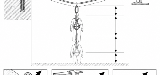 Deflection of an EN 795 Type C line adds to the required clearance, and the end anchors see forces well above Oblique Anchors and Fall Distance: How Later
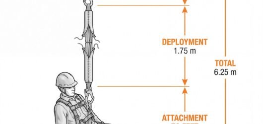 Diagram showing the four components of energy absorber clearance measured down from the anchor: lanyard 2.0 m,Energy Absorber Clearance: How to Calculate
 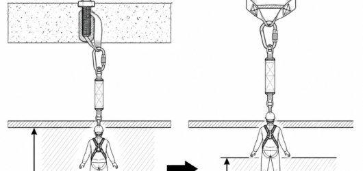 Raising the anchor converts required clearance into height above the platform, cutting the space needed undernEnergy Absorber Clearance: How to Calculate
 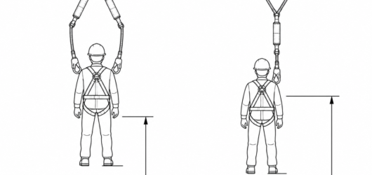 Y lanyards come in two constructions; the number and position of the absorber packs changes how clearance is cEnergy Absorber Clearance: How to Calculate
 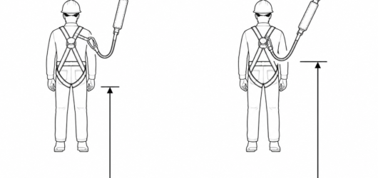 Correct: free leg parked on the dedicated parking element. Incorrect: free leg clipped to the dorsal D-ring, wEnergy Absorber Clearance: How to Calculate
 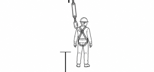 The clearance decision starts on the label: assembly length, permitted mass range and declared deployment.Energy Absorber Clearance: How to Calculate
 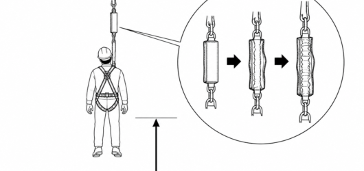 Any absorber showing full or partial deployment is withdrawn from service; its remaining deployment length is Energy Absorber Clearance: How to Calculate
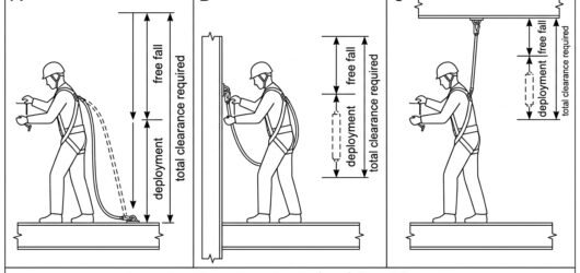
 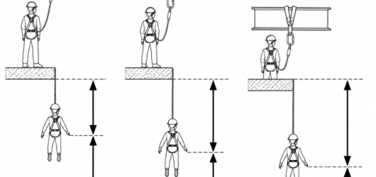 Same lanyard, three anchor heights: every metre the anchor drops adds a metre of free fall and a metre of requUnderstanding and Optimising Fall Clearance
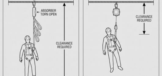 Comparison diagram of clearance required for a 2 m energy-absorbing lanyard versus an overhead retractable typUnderstanding and Optimising Fall Clearance
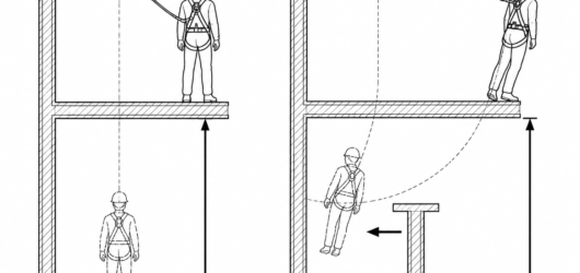 Working off to one side lowers the bottom of the fall and puts structure in the swing path.Understanding and Optimising Fall Clearance
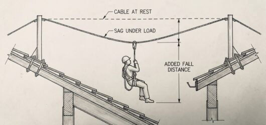 Diagram of a fallen worker mid-span on an EN 795 Type C horizontal flexible anchor line, showing line sag addiUnderstanding and Optimising Fall Clearance
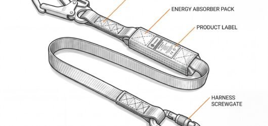 Labelled energy-absorbing fall-arrest lanyard showing the anchor hook, webbing leg, energy absorber pack, prodHow and Why to Use a Fall-Arrest Lanyard
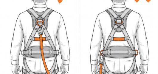 Rear-view comparison of a fall-arrest lanyard correctly connected to the dorsal D-ring between the shoulder blHow and Why to Use a Fall-Arrest Lanyard
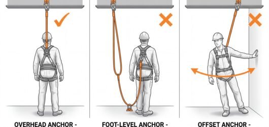 Three-panel comparison of anchor position: an overhead anchor giving the shortest fall, a foot-level anchor crHow and Why to Use a Fall-Arrest Lanyard
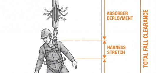 Fall clearance diagram below an overhead beam anchor, stacking lanyard length, energy absorber deployment, harHow and Why to Use a Fall-Arrest Lanyard
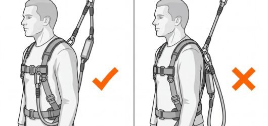 Comparison of a twin-leg fall-arrest lanyard with the unused leg correctly parked on the harness keeper, againHow and Why to Use a Fall-Arrest Lanyard
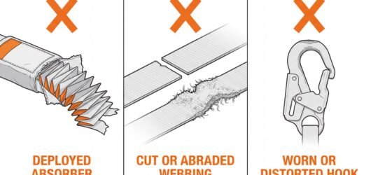 Three fall-arrest lanyard reject criteria: a deployed energy absorber with exposed tear-webbing, cut or abradeHow and Why to Use a Fall-Arrest Lanyard
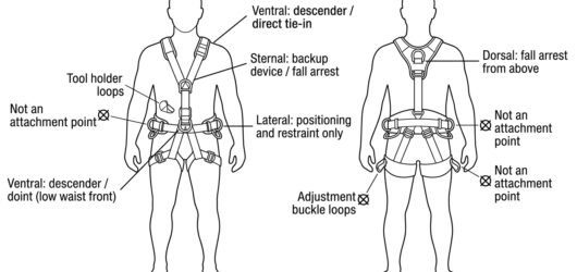 Diagram of harness attachment points showing ventral, sternal, dorsal and lateral belt points with the rope fuAttaching a Rope to the Harness: Attachment
 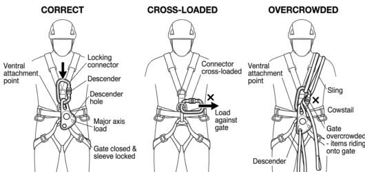 Three-panel comparison of a descender connector at the harness ventral point: correct major-axis loading, crosAttaching a Rope to the Harness: Attachment
 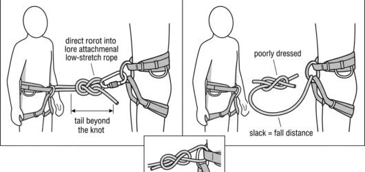 Comparison diagram of a figure-eight on a bight tie-in to a harness: correctly dressed with adequate tail and Attaching a Rope to the Harness: Attachment
 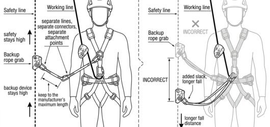 Diagram of a two-rope system showing a descender on the working line and a backup device on the safety line, eAttaching a Rope to the Harness: Attachment
 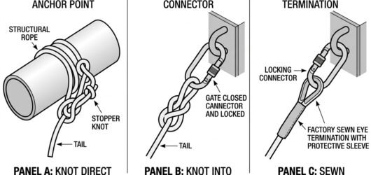 Diagram comparing three ways of attaching a rope to the anchor: knot direct onto the anchor point, figure-eighAttaching a Rope to the Anchor: Knots, Conne
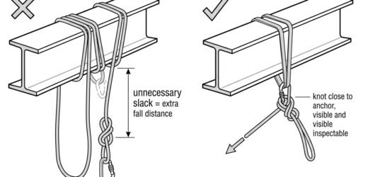 Comparison diagram showing an incorrect long slack loop between the beam and the knot versus a correct terminaAttaching a Rope to the Anchor: Knots, Conne
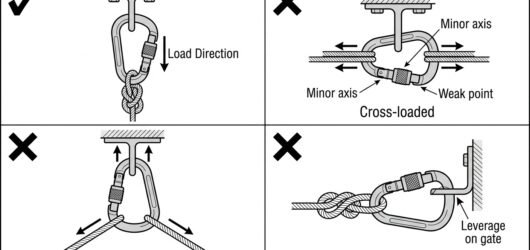 Four-panel diagram of connector loading at an anchor: correct major-axis loading versus cross-loading, three-wAttaching a Rope to the Anchor: Knots, Conne
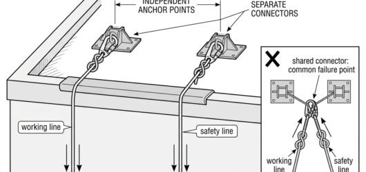 Diagram showing working line and safety line terminated on separate anchor points with separate connectors, anAttaching a Rope to the Anchor: Knots, Conne
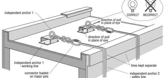 Diagram of a working line and safety line rigged to two independent rooftop anchors with locking connectors anInstalling Ropes for a Descent: Anchors, Rop
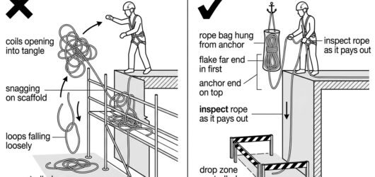 Comparison diagram showing an uncontrolled thrown coil versus controlled rope deployment from a rope bag with Installing Ropes for a Descent: Anchors, Rop
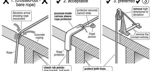 Diagram comparing bare rope on a sharp edge, a secured rope protector, and raising the rope clear of the edge Installing Ropes for a Descent: Anchors, Rop
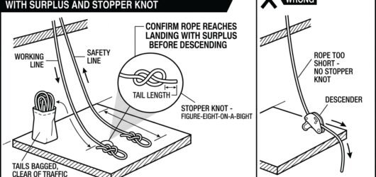 Diagram of rope ends at the landing showing figure-eight stopper knots, surplus rope bagged, and a crossed-outInstalling Ropes for a Descent: Anchors, Rop
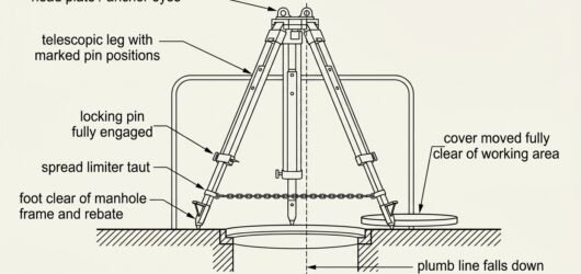 Line diagram of a tripod erected over an open manhole showing head anchor eyes, pinned telescopic legs, taut sSetting Up a Tripod Over a Manhole: Footing,
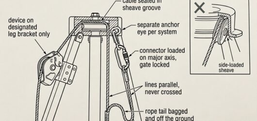 Diagram of tripod head rigging showing a rescue lifting device on its leg bracket, cable seated in the head shSetting Up a Tripod Over a Manhole: Footing,
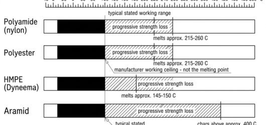 Diagram comparing working temperature ranges and melting or charring thresholds for polyamide, polyester, HMPETemperature and Chemical Limits for Textiles
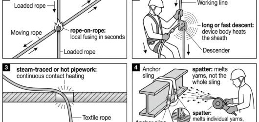 Four-panel diagram of heat sources that damage rope access textiles: rope-on-rope friction, descender heating,Temperature and Chemical Limits for Textiles
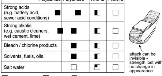 Chemical compatibility matrix showing how acids, alkalis, bleach, solvents and salt water affect polyamide, poTemperature and Chemical Limits for Textiles
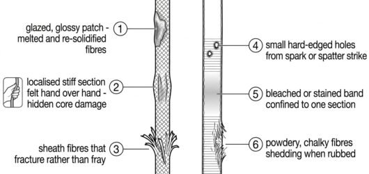 Inspection diagram showing signs of heat and chemical damage on kernmantle rope and webbing, including glazingTemperature and Chemical Limits for Textiles
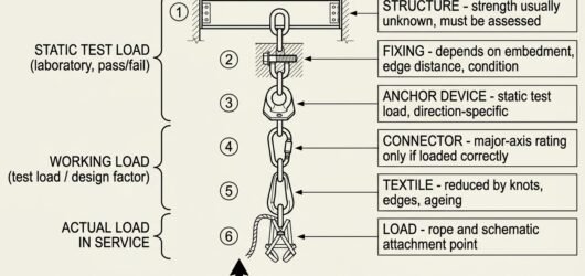 Diagram of the anchor load path from structure through fixing, anchor device, connector and sling to the load,Anchor Strength Requirements Explained: Test
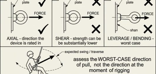 Three-panel diagram comparing axial, shear and levered loading on an anchor eyebolt, plus a plan view showing Anchor Strength Requirements Explained: Test
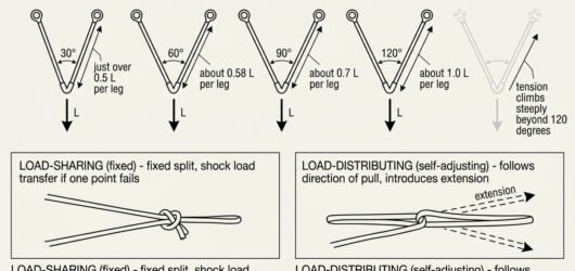 Diagram showing leg tension in a two-point anchor at 30, 60, 90 and 120 degree internal angles, and the differAnchor Strength Requirements Explained: Test
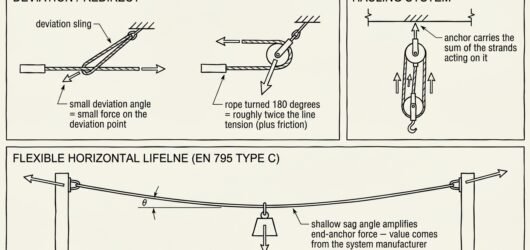 Diagram of three load-multiplying anchor cases: rope deviation versus 180-degree redirect, a hauling system anAnchor Strength Requirements Explained: Test
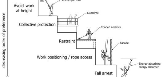 Diagram showing the hierarchy of control for work at height: avoid, collective protection, restraint, work posGeneral Principles for Work at Height: The O
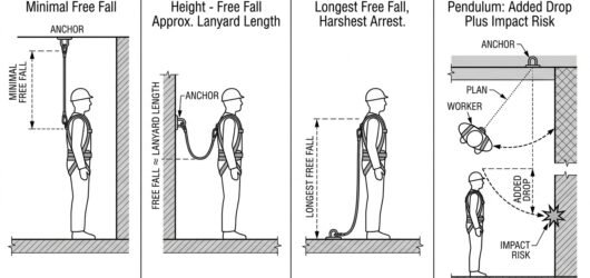 Four-panel diagram comparing anchor positions overhead, at harness height and at foot level, plus a panel showGeneral Principles for Work at Height: The O
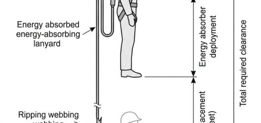 Fall clearance diagram showing the stacked components of required clearance: free fall, absorber deployment, hGeneral Principles for Work at Height: The O
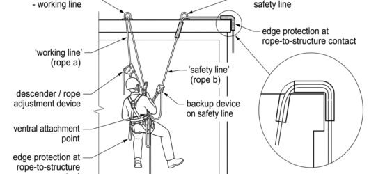 Diagram of a two-rope rope access system showing independent anchors, a descender on the working line, a backuGeneral Principles for Work at Height: The O
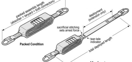 Diagram comparing a packed energy absorbing lanyard with the same lanyard after deployment, showing deploymentEnergy Absorber Deployment Lengths: What The
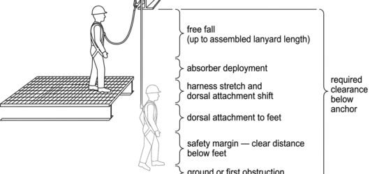 Vertical clearance stack diagram showing free fall, absorber deployment, harness shift, body length and safetyEnergy Absorber Deployment Lengths: What The
 Three-panel diagram comparing anchor at foot level, shoulder level and overhead, showing reduced free fall, reEnergy Absorber Deployment Lengths: What The
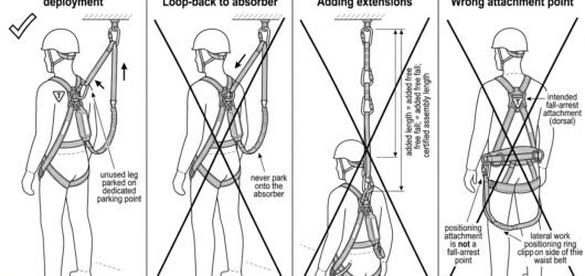 Diagram showing correct parking of an unused twin-leg lanyard arm and three incorrect configurations that add Energy Absorber Deployment Lengths: What The
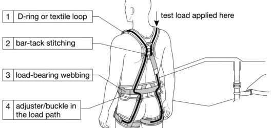 Diagram showing the dorsal harness attachment point as a rated load path through D-ring, stitching, shoulder wHarness Attachment Point Strength Ratings: W
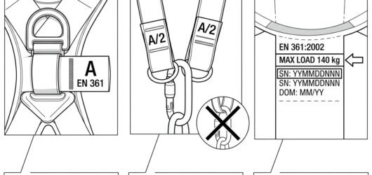 Close-up diagram of harness markings showing an A fall-arrest point, paired A/2 loops used together, and a harHarness Attachment Point Strength Ratings: W
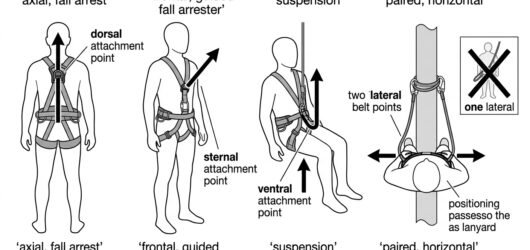 Diagram comparing tested loading directions for dorsal, sternal, ventral and paired lateral harness attachmentHarness Attachment Point Strength Ratings: W
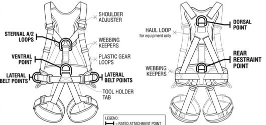 Front and rear harness diagram distinguishing rated attachment points from unrated gear loops, tool holders anHarness Attachment Point Strength Ratings: W
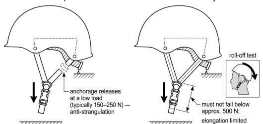 Diagram contrasting the EN 397 releasing chin strap anchorage with the EN 12492 high-strength retention systemHelmet Standards: EN 397 and EN 12492
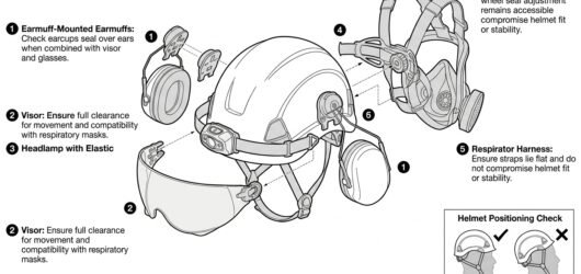 Diagram of helmet accessory compatibility: slot-mounted earmuffs and visor, headlamp clips, cradle adjustment Helmet Standards: EN 397 and EN 12492
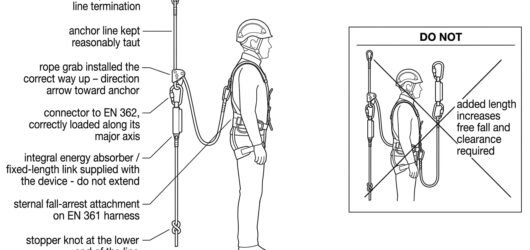 Diagram of a correctly assembled rope grab system on a vertical lifeline with harness attachment, connector, aRope Grab Specifications and Rope Compatibil
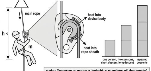 Diagram showing how descent height, mass and number of descents accumulate energy that becomes heat in the desDescender Specifications and Working Loads:
 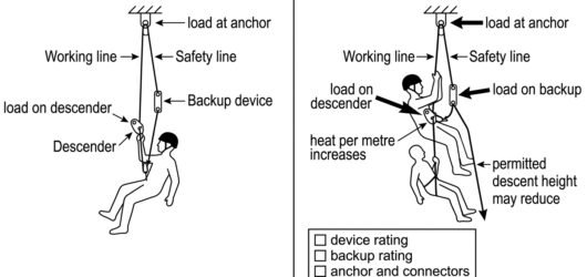 Two-panel diagram comparing loads on descender, backup device and anchor for a single user versus a rescuer wiDescender Specifications and Working Loads:
 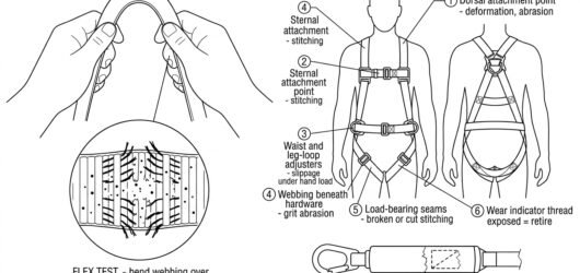 Diagram showing the webbing flex test opening the weave to reveal cut yarns, plus numbered harness inspection Service Life and Retirement Criteria for Tex
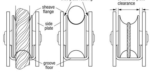 Cross-section diagram comparing correct, oversize and undersize rope diameter seated in a pulley sheave grooveUsing Pulleys With Small-Diameter Rope or Co
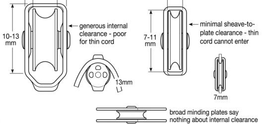 Comparison diagram of a wide-body rigging pulley, a compact micro pulley and a prusik-minding pulley, showing Using Pulleys With Small-Diameter Rope or Co
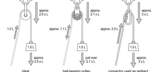 Three free-body diagrams comparing anchor load on a 180-degree redirect at 100%, 90% and 50% pulley efficiencyPulley Efficiency: What the Numbers Mean
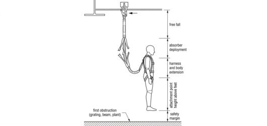 Diagram showing the stacked components of required fall clearance below an anchor: free fall, absorber deploymChoosing an Absorber for the Clearance Avail
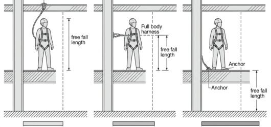 Three-panel comparison of anchor height — overhead, at attachment level, and at foot level — and the increasinChoosing an Absorber for the Clearance Avail
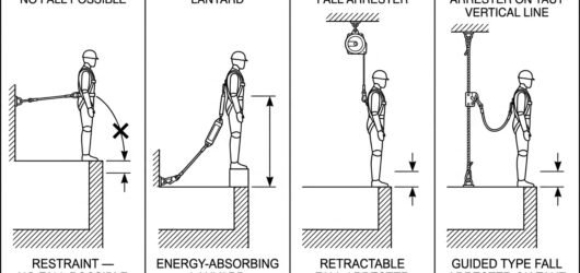 Comparison of restraint, energy-absorbing lanyard, retractable fall arrester and guided type fall arrester andChoosing an Absorber for the Clearance Avail
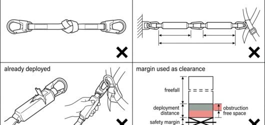 Four incorrect attempts to gain fall clearance: knotting the lanyard, two absorbers in series, reusing a deploChoosing an Absorber for the Clearance Avail
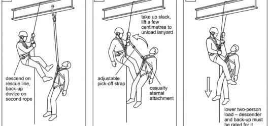 Three-panel diagram of a rope-access pick-off showing the rescuer descending, attaching an adjustable pick-offSelecting a Rescue Kit for the Task
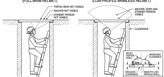 Diagram showing how a full-brim helmet blocks upward vision in a manhole while a low-profile brimless helmet pSelecting a Helmet for Confined Space Work:
 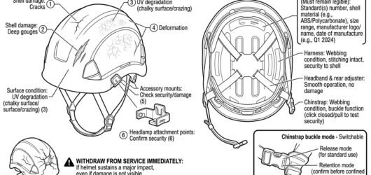 Inspection diagram of a safety helmet showing exterior damage checks, internal markings, harness and chinstrapSelecting a Helmet for Confined Space Work:
  Line diagram identifying rear and lateral belt points, sternal, dorsal and ventral harness points that can be Which Attachment Points to Use for Restraint
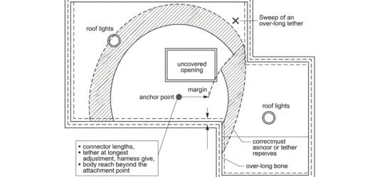 Plan-view diagram of a flat roof showing the restraint arc from a single anchor kept short of edges, openings Which Attachment Points to Use for Restraint
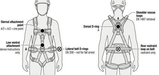 Diagram of a full body harness front and back showing sternal and dorsal fall-arrest A points valid for a ropeHarness Attachment Point for a Rope Grab: St
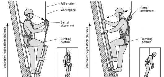 Side-by-side diagram comparing sternal and dorsal rope grab attachment, showing device visibility, rope routinHarness Attachment Point for a Rope Grab: St
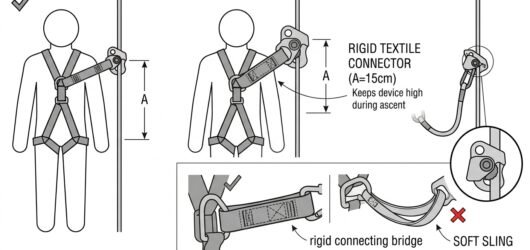 Diagram showing correct short direct rope grab connection versus incorrect chained connectors and added lanyarHarness Attachment Point for a Rope Grab: St
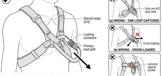 Close-up diagram of a locking connector at the sternal harness attachment showing both A/2 loops captured and Harness Attachment Point for a Rope Grab: St
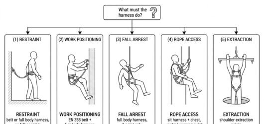 Decision chart mapping five work tasks — restraint, work positioning, fall arrest, rope access and extraction Which Harness for Which Use? A Selection Not
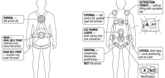 Front and rear views of a combination full body harness with every attachment point labelled by its certified Which Harness for Which Use? A Selection Not
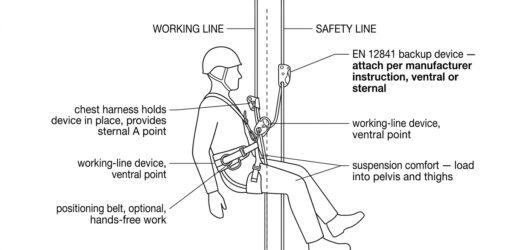 Side view of a rope access technician on working and safety lines, showing the ventral attachment for the descWhich Harness for Which Use? A Selection Not
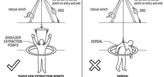 Comparison of confined space extraction through a manhole using shoulder extraction points with a spreader barWhich Harness for Which Use? A Selection Not
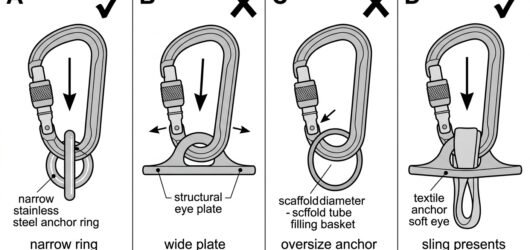 Diagram comparing a locking connector correctly seated in a narrow anchor ring versus levered on a wide eye plChoosing Connectors for Anchor Rigging: Shap
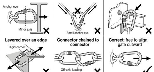 Diagram of anchor connector loading faults: cross-loading, three-way loading, gate pressed on structure, leverChoosing Connectors for Anchor Rigging: Shap
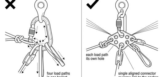 Diagram comparing four load paths crowded into a single anchor carabiner versus a rigging plate giving each loChoosing Connectors for Anchor Rigging: Shap
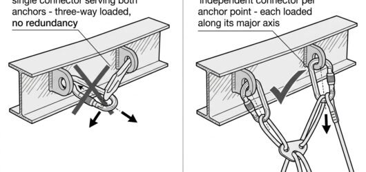 Diagram showing one connector clipped into two anchor eyes as an incorrect shared link versus two independent Choosing Connectors for Anchor Rigging: Shap
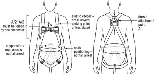 Front and back diagram of a full body harness showing the dorsal A point, paired A/2 chest loops, and the beltConnecting a Fall-Arrest Lanyard to the Harn
 Comparison diagram showing a correct single locking connector at the harness attachment versus a girth-hitchedConnecting a Fall-Arrest Lanyard to the Harn
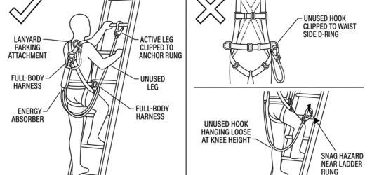 Diagram of a twin-leg lanyard with both legs on one dorsal attachment and the spare leg stowed on a dedicated Connecting a Fall-Arrest Lanyard to the Harn
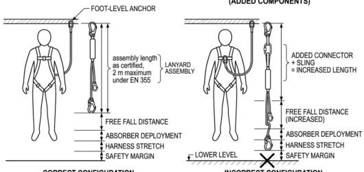 Elevation diagram comparing a certified energy-absorbing lanyard assembly with one extended by extra connectorConnecting a Fall-Arrest Lanyard to the Harn
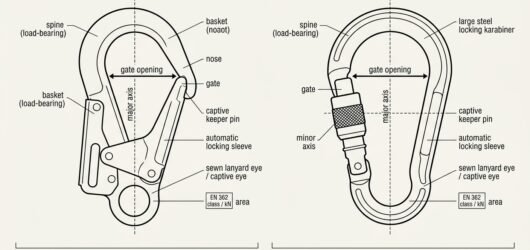 Labelled diagram of a large-opening scaffold hook and a locking karabiner showing spine, basket, nose, keeper Lanyard-End Connector for Fall Arrest: Gate
 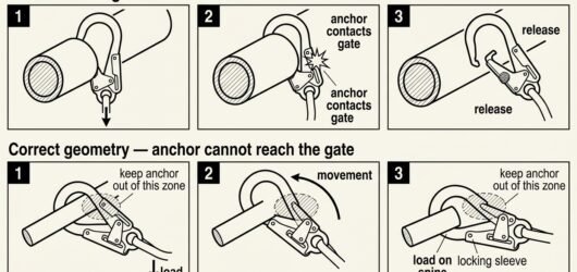 Six-frame diagram comparing roll-out of a hook on an oversized anchor with correct geometry where the anchor sLanyard-End Connector for Fall Arrest: Gate
 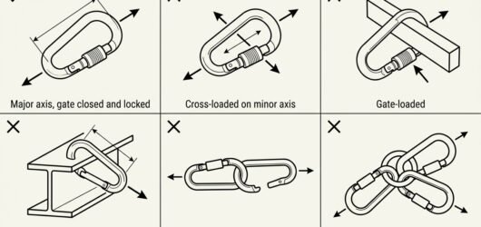 Six-panel diagram showing correct major-axis loading of a fall-arrest connector alongside cross-loading, gate Lanyard-End Connector for Fall Arrest: Gate
 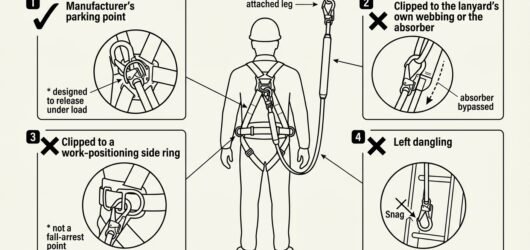 Diagram of a twin-leg lanyard showing the correct manufacturer parking point for the unused hook and three incLanyard-End Connector for Fall Arrest: Gate
 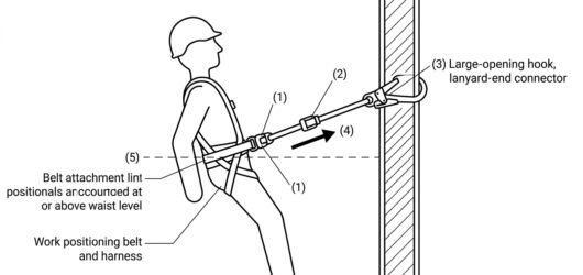 Diagram of a work positioning setup showing harness-end connector on the belt lateral attachment point, the adLanyard-End Connector for Work Positioning:
 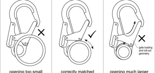 Three-panel diagram comparing an undersized, correctly matched and oversized connector gate opening on a roundLanyard-End Connector for Work Positioning:
 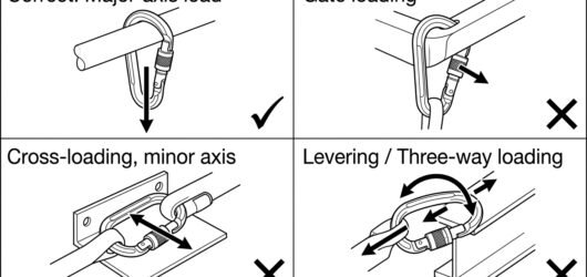 Four-panel diagram showing correct major-axis loading of a work positioning lanyard connector versus gate loadLanyard-End Connector for Work Positioning:
 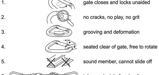 Six-step pre-clip check diagram for a work positioning lanyard-end connector covering gate action, nose and hiLanyard-End Connector for Work Positioning:
 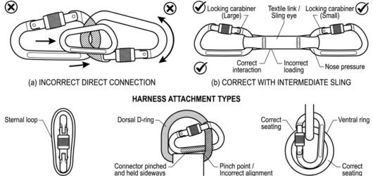 Diagram of two carabiners clipped directly together versus connected through a soft link, and the same connectChecking Connector Compatibility: A Field Me
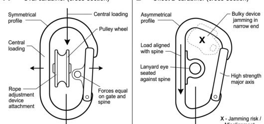 Two-panel diagram showing an oval connector keeping a pulley and rope device centred, versus an offset D loadiConnector Shapes and Where Each Belongs
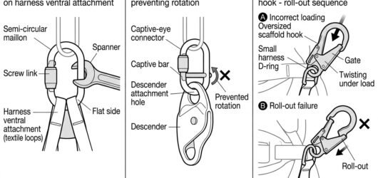 Diagram showing a semi-circular maillon on a harness attachment, a captive-eye connector holding a descender iConnector Shapes and Where Each Belongs
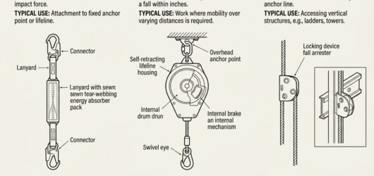 Line diagram comparing an energy-absorbing lanyard, a retractable fall arrester and a guided type fall arresteWhich Type of Fall-Arrest Lanyard to Choose:
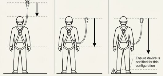 Three-panel diagram showing fall factor for overhead, level and foot-level anchor positions with a full body hWhich Type of Fall-Arrest Lanyard to Choose:
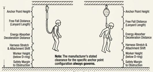 Diagram of fall clearance stack-up comparing an energy-absorbing lanyard and a retractable fall arrester belowWhich Type of Fall-Arrest Lanyard to Choose:
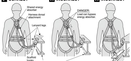 Diagram showing correct and incorrect parking of the unused leg of a twin-leg energy-absorbing lanyardWhich Type of Fall-Arrest Lanyard to Choose:
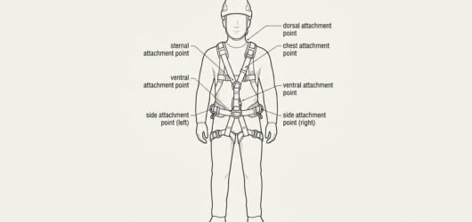 Line diagram of a standing worker in a correctly adjusted full body harness with labels for snug leg loops, miAdjusting a Full Body Harness Correctly: Fit
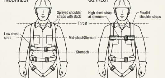 Comparison diagram showing a harness chest strap worn incorrectly low on the stomach versus correctly positionAdjusting a Full Body Harness Correctly: Fit
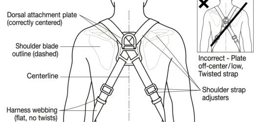 Rear view diagram of a harness dorsal attachment point centred between the shoulder blades with flat untwistedAdjusting a Full Body Harness Correctly: Fit
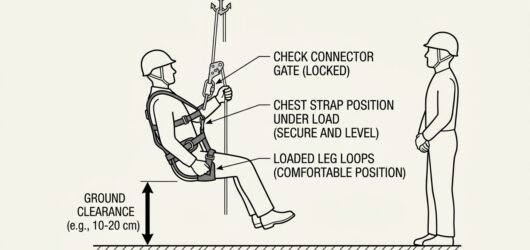 Diagram of a worker performing a pre-use hang check by briefly weighting the harness at low height above the fAdjusting a Full Body Harness Correctly: Fit
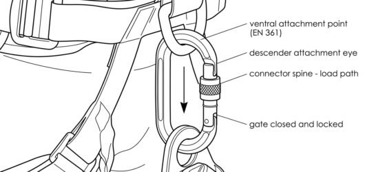 Line diagram of a locking connector joining a descender's attachment eye to a harness ventral attachment pointChoosing a Connector for a Descender: Lockin
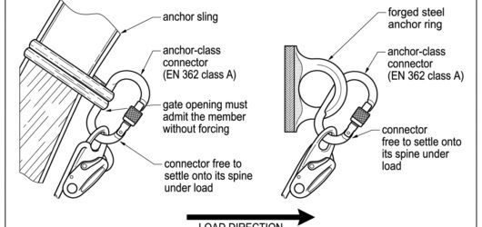 Line diagram of the anchor side of a descender attached with a large locking connector to an anchor sling arouChoosing a Connector for a Descender: Lockin
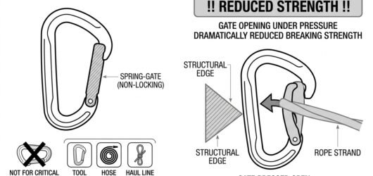 Line diagram of a non-locking spring-gate connector being pushed open by a rope and an edge, marked as unsuitaConnector Locking Systems Compared: Screw-Lo
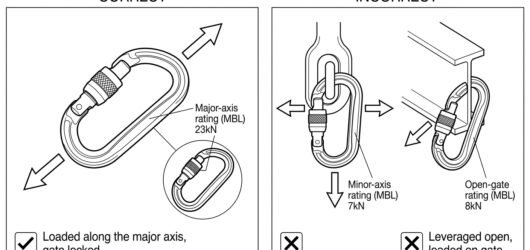 Diagram comparing a connector correctly loaded along its major axis with incorrect minor-axis cross loading anConnector Locking Systems Compared: Screw-Lo
Rope access 80
 A suspended load with a tag line running down to a handler standing well outside the load radius, beside a secTag Lines and Controlling a Swinging Load
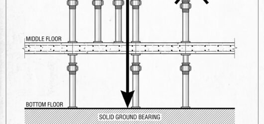 Section showing propping to a soffit with the load path traced down through each floor to a solid bearing, besTemporary Works: What Needs a Design and an
 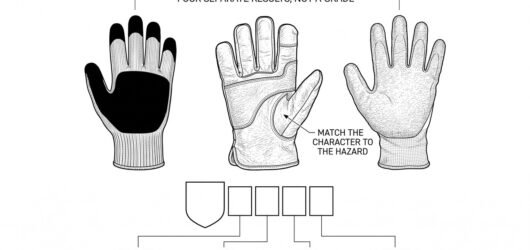 Three construction gloves side by side with the EN 388 pictogram and its performance string shown enlarged, anGloves for Construction Handling: Matching E
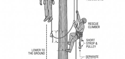 Simple line-art illustration of a ground-based rescuer ascending a rope toward an incapacitated climber positiRescue Planning for Aerial Tree Work
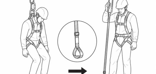 Correct: a conscious casualty deploys the suspension relief strap and stands, unloading the leg loops while thRelease and Rescue from a Long Rope: Getting
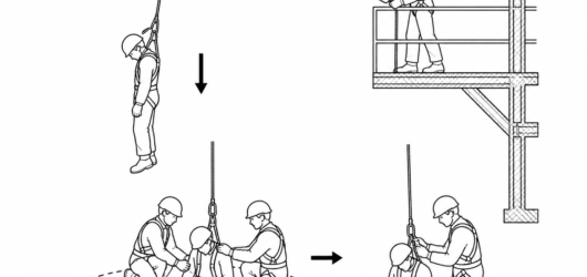 The casualty is disconnected only once fully supported on the ground, inside a cleared and attended landing arRelease and Rescue from a Long Rope: Getting
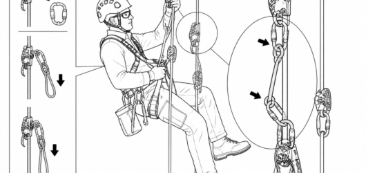 Changeover to raise: the progress capture is added on the load side, the Z-rig is built on the same rope, and Hauling: Building a Combined Lowering and Ra
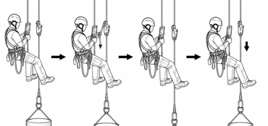
 Correct: the descender stays captive in the loaded line. Incorrect: descender removed, load held only on a tooHauling: Building a Combined Lowering and Ra
 A load-releasing arrangement gives a controlled way to shift tension off the progress capture and back onto thHauling: Building a Combined Lowering and Ra
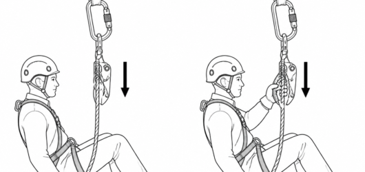 Left, correct: hand clear of the device, cam engaged. Right, incorrect: gripping the housing holds the cam opeAccompanied Descent with a Rope Grab: Riggin
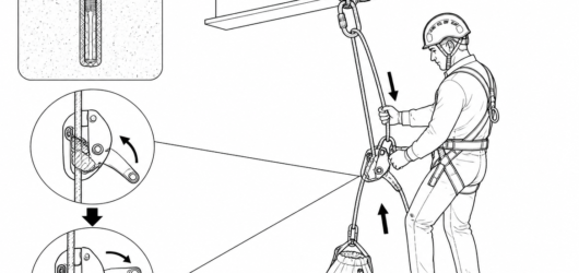 Control comes from the brake hand on the free strand; the handle only modulates how far the cam releases. The Haul System with a Descender: Rigging, Limit
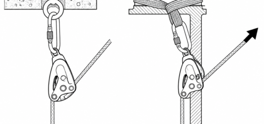 Correct: the descender hangs free and aligns with the pull. Incorrect: an off-axis haul traps the device againHaul System with a Descender: Rigging, Limit
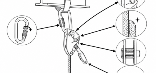 Pre-use check: cam rotates freely and returns, teeth clean, side plate and axle sound, connector sleeve fully Haul System with a Descender: Rigging, Limit
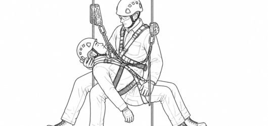 Accompanied descent configuration: descender on the working line, independent backup on a second line, casualtAccompanied Descent Rescue: How the Manoeuvr
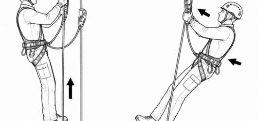 Correct: hips directly under the chest ascender and arms straight, so every push travels vertically. IncorrectGreater Efficiency on Rope Ascents: Techniqu
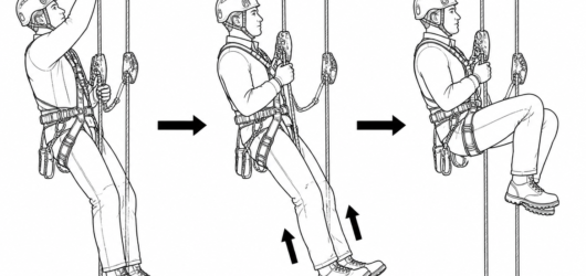 One efficient cycle: reach high, drive with the legs, then transfer the weight onto the chest ascender before Greater Efficiency on Rope Ascents: Techniqu
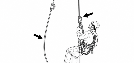
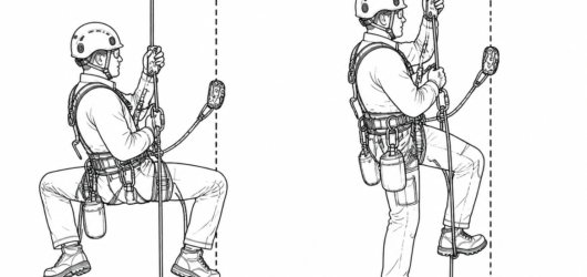 Frog set-up (left) versus rope-walking set-up (right); in both cases the safety line, shown dashed, is indepenGreater Efficiency on Rope Ascents: Techniqu
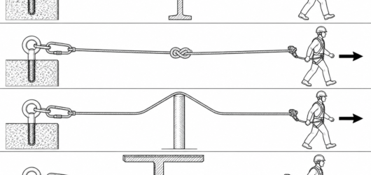 Four different obstacles, four different solutions — an intermediate bracket, a mid-line knot, a deviation andApproaching an Obstacle with a Rope Grab: Ho
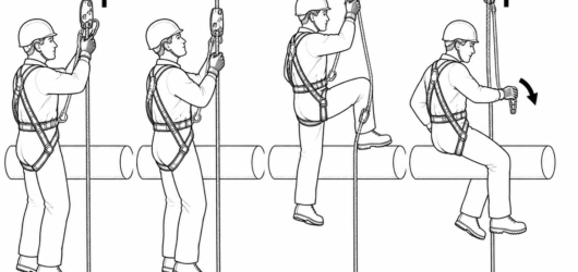 The order is fixed: attach, check, load, then release. The original attachment is never removed first.Approaching an Obstacle with a Rope Grab: Ho
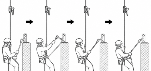 At a re-belay, one rope is transferred at a time — the back-up device stays high on the safety line and the twApproaching an Obstacle with a Rope Grab: Ho
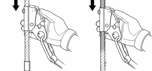 Left: serviceable line with intact sheath and lower end termination. Right: reject — abrasion, glazing, core dFunction Testing a Rope Grab Every Time It's
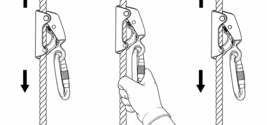 The three-part function test: free travel up and down, immediate lock-up under a brisk downward pull, then cleFunction Testing a Rope Grab Every Time It's
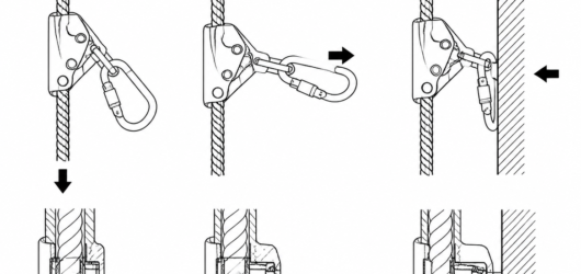 Correct: sleeve fully locked, load along the major axis, gate free of contact. Incorrect: cross-loaded, gate bFunction Testing a Rope Grab Every Time It's
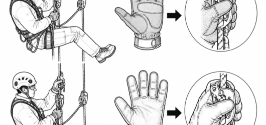 Correct: close-fitting glove with cut protection across the palm-side fingers and thumb crotch. Incorrect: oveUsing PPE for Material Handling: Ground-Leve
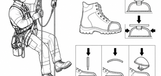 EN ISO 20345 toecaps are tested to 200 J impact and 15 kN compression; sole penetration resistance (P, PL or PUsing PPE for Material Handling: Ground-Leve
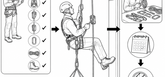 Pre-use checks happen before every load; periodic examination by a competent person follows the manufacturer'sUsing PPE for Material Handling: Ground-Leve
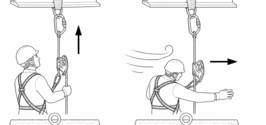 Correct: load acting along the rope axis. Incorrect: wind pushing the user and a flat load sideways loads the Rope Grab Behaviour in High Winds: What Chan
 Base tension is a re-check item: wind can lift the lower line or swing the tensioning weight onto structure soRope Grab Behaviour in High Winds: What Chan
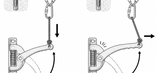 Correct: cord tied to the handle where hand force is intended and routed so the pull stays in the plane of theRemote Control of a Descender Handle with a
 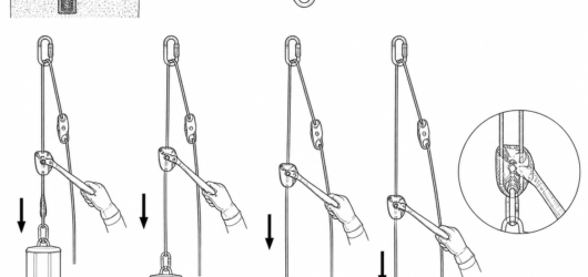 Configuration B: the cord angle at the handle changes continuously as the load descends, altering how much hanRemote Control of a Descender Handle with a
 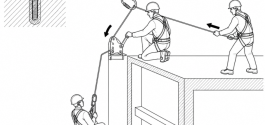 Usually preferable to remoting the handle: hand operation at the device plus a dedicated operator on the brakeRemote Control of a Descender Handle with a
  Doubled-rope pull-down: the rope runs through a free-hanging metal ring, never around the beam or across the sRetrievable Rope Rigging: How to Set Up a Pu
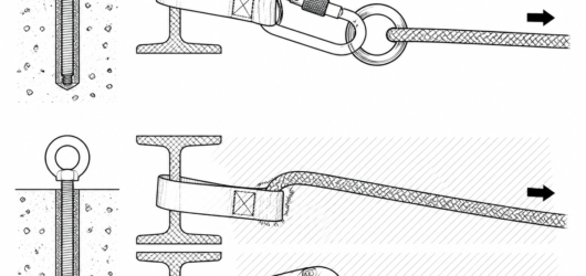 Correct: rope runs on a smooth metal ring. Incorrect (hatched): rope bearing on webbing or on a connector gateRetrievable Rope Rigging: How to Set Up a Pu
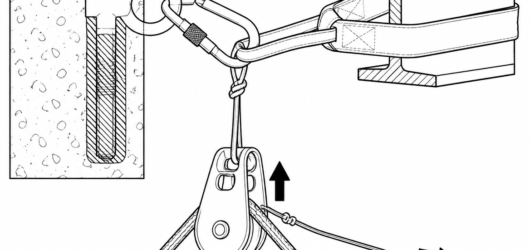 Single-line configuration: the thin retrieval cord releases the block. It carries no person and must be baggedRetrievable Rope Rigging: How to Set Up a Pu
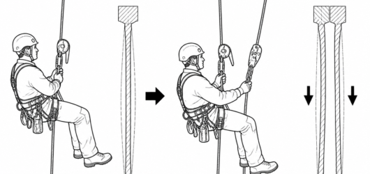 Splitting the load between two tensioned lines roughly halves the tension in each rope, and with it the elongaLimiting Rope Stretch with Two Descenders: L
 Correct: braking carabiner in the descender's designated attachment hole, tail rope routed through it, brake hDescending with Additional Braking: When a D
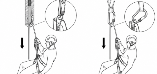 Left: correct braking point on the device. Right: incorrect — gear loops are not rated for functional loads anDescending with Additional Braking: When a D
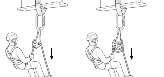 Adding a wrap through a braking connector lengthens the rope's friction path, so the same hand force on the taDescending with Additional Braking: When a D
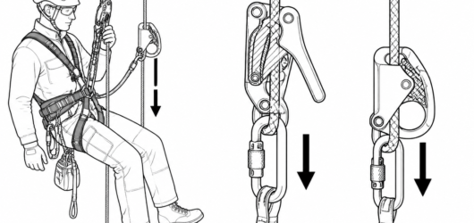 Additional braking sits on the working line only — the Type A backup device on the safety line must remain freDescending with Additional Braking: When a D
 Two-person loads: confirm the device carries an EN 341:2011 rescue rating for that mass and rope, and rehearseDescending with Additional Braking: When a D
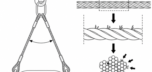 Broken wires are counted within one rope lay length; five breaks clustered in a single strand is a widely applWire Strop Inspection: What to Check Before
 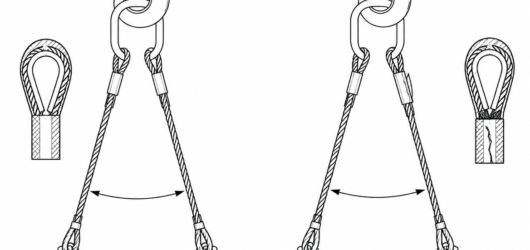 Correct, left: ferrule sound and seated, legs parallel, thimble snug. Reject, right: cracked ferrule that has Wire Strop Inspection: What to Check Before
 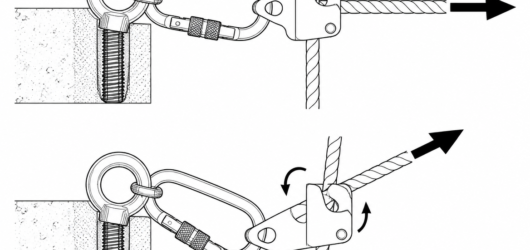 Correct: clamp loaded in line with the rope, connector loaded along its major axis. Incorrect: off-axis pull rUsing a Single Rope Clamp: Why Not?
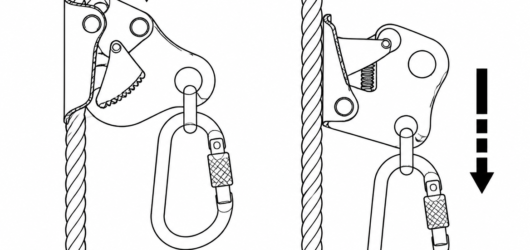 Left: correct orientation, cam engaged under downward load. Right: inverted device – the cam cannot bite and tWork Positioning with a Rope Grab: Standards
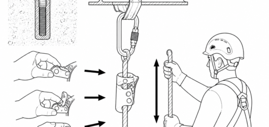 Pre-use check every time: cam teeth and catch function, device body, connector, and the full working length ofWork Positioning with a Rope Grab: Standards
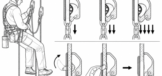 An ascender grips harder as load increases — downward movement is only possible with the device fully unloadedAscender Down-Climb: Losing a Short Distance
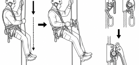 Increment down-climb for one to two metres of clean rope; changeover to an EN 12841 Type C descender for anythAscender Down-Climb: Losing a Short Distance
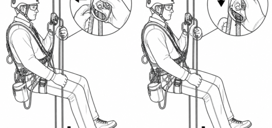 Correct: device fully unloaded, cam released by thumb, rope held taut below. Incorrect: loaded cam forced downAscender Down-Climb: Losing a Short Distance
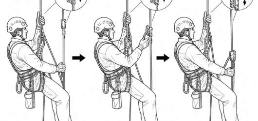 Reset the backup at the start of every increment: slack in the safety line is the main hazard when travelling Ascender Down-Climb: Losing a Short Distance
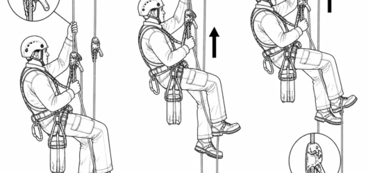 Short ascent: the descender stays on the working line, so no system change is needed to resume descent or workLong or Short Rope Ascent: Choosing the Tech
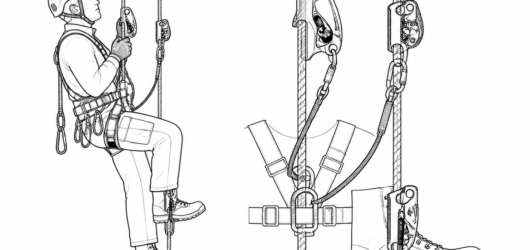 Frog system: the chest ascender holds position and keeps the torso upright while the legs do the work — Long or Short Rope Ascent: Choosing the Tech
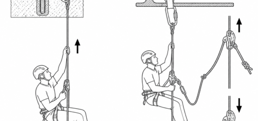 Rope-walking suits long, clean, plumb free hangs; the frog handles deviations, rebelays and knot passes with fLong or Short Rope Ascent: Choosing the Tech
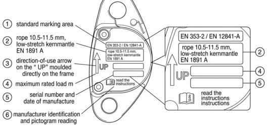 Labelled diagram of the markings on a rope grab side plate showing standard, rope diameter range, direction arRope Grab Specifications and Rope Compatibil
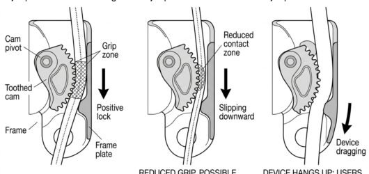 Cross-section comparison of a rope grab cam on correctly sized, undersized and oversized rope showing grip, slRope Grab Specifications and Rope Compatibil
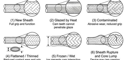 Six close-up diagrams of rope sheath conditions – new, glazed, contaminated, flattened, iced and ruptured – wiRope Grab Specifications and Rope Compatibil
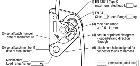 Line diagram of a descender side plate with numbered callouts to EN 12841 Type C rating, EN 341 class and loadDescender Specifications and Working Loads:
 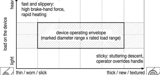 Chart showing a descender's operating envelope with load on the vertical axis and rope diameter and condition Descender Specifications and Working Loads:
 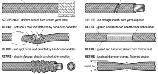 Six panel diagram comparing acceptable rope sheath fuzz with retirement defects: core exposure, core void, glaService Life and Retirement Criteria for Tex
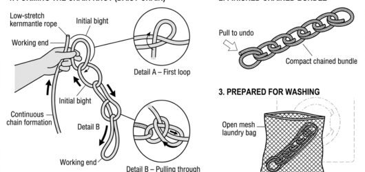 Diagram showing a low-stretch rope being chain-knotted into a compact daisy chain and placed in a mesh laundryWashing a Low-Stretch Rope Before First Use
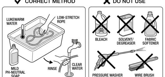 Comparison diagram of correct and incorrect washing methods for a low-stretch rope, contrasting mild soap and Washing a Low-Stretch Rope Before First Use
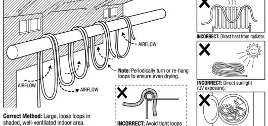 Diagram of correct rope drying in large loose loops in shade with airflow, contrasted with crossed-out drying Washing a Low-Stretch Rope Before First Use
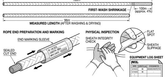 Diagram showing a washed rope measured shorter than its nominal length, its end re-marked with identification Washing a Low-Stretch Rope Before First Use
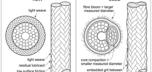 Cross-section diagram comparing a new kernmantle rope with a tight round sheath to a used rope with fuzzed fibPerformance of New Versus Used Ropes: Slip,
 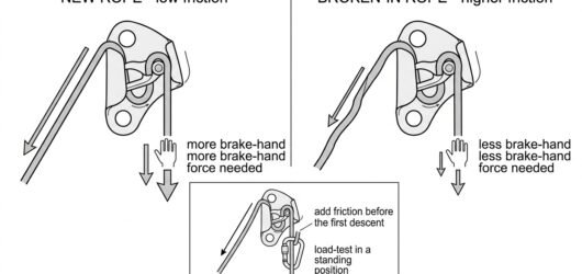 Diagram comparing descender friction on new slick rope versus broken-in rope, with an inset showing an added fPerformance of New Versus Used Ropes: Slip,
 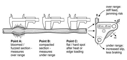 Diagram showing a used rope measured with calipers at bloomed, compacted and flattened sections against a descPerformance of New Versus Used Ropes: Slip,
 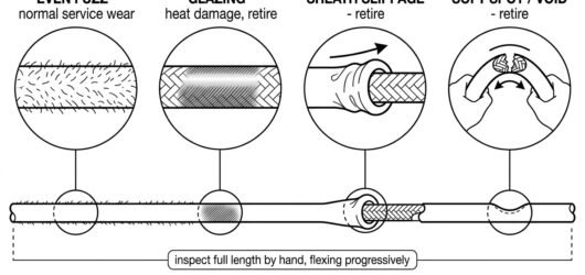 Rope inspection diagram with magnified details of even fuzz, glazing, sheath slippage and a soft spot found byPerformance of New Versus Used Ropes: Slip,
 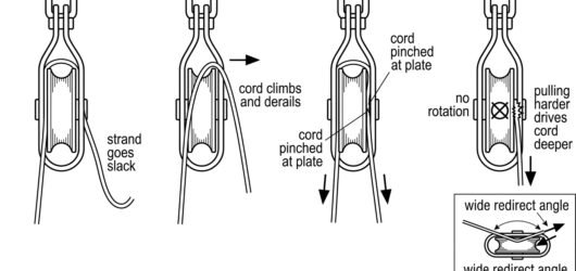 Four-step diagram showing small-diameter cord going slack, derailing over the sheave flange, jamming between sUsing Pulleys With Small-Diameter Rope or Co
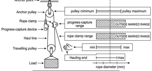 Diagram of a hauling system with each device's marked rope diameter range shown as tolerance bars on a common Using Pulleys With Small-Diameter Rope or Co
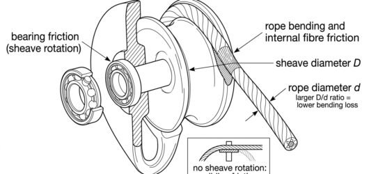 Cutaway diagram of a pulley showing bearing friction at the axle and rope bending loss around the sheave, withPulley Efficiency: What the Numbers Mean
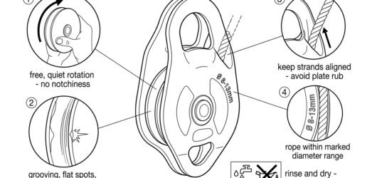 Inspection diagram of a pulley with four callouts: free sheave rotation, sheave groove wear, strand alignment Pulley Efficiency: What the Numbers Mean
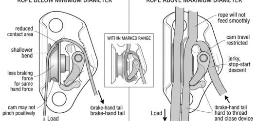 Cut-away diagrams comparing a too-thin, correct and too-thick rope inside a descender's rope channel, showing Rope Diameter Limits on Descenders: Why the
 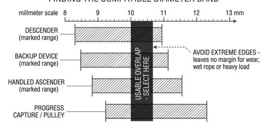 Bar chart showing the marked rope diameter ranges of a descender, backup device, ascender and pulley overlappiRope Diameter Limits on Descenders: Why the
 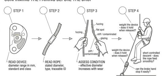 Four-step diagram of checking descender and rope compatibility: read device marking, read rope marking, assessRope Diameter Limits on Descenders: Why the
 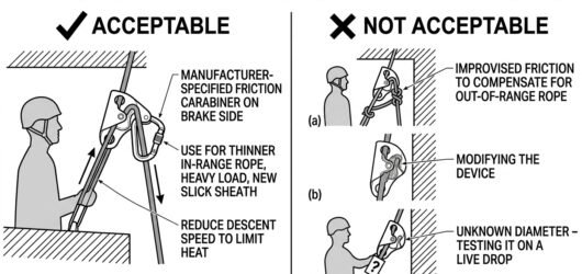 Comparison diagram showing an acceptable manufacturer-specified friction carabiner on the brake side versus unRope Diameter Limits on Descenders: Why the
 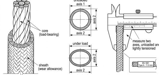 Cross-section diagram of kernmantel rope showing core and sheath, plus caliper measurement on two axes to checChoosing a Low-Stretch Rope Diameter: Matchi
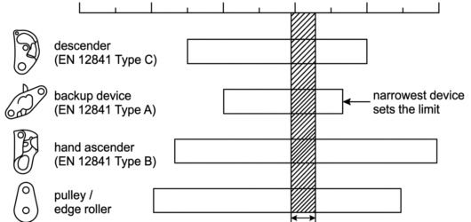 Diagram showing overlapping marked diameter ranges of descender, backup device, ascender and pulley, with the Choosing a Low-Stretch Rope Diameter: Matchi
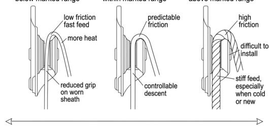 Three-panel sectional diagram of a descender with rope below, within and above the marked diameter range, showChoosing a Low-Stretch Rope Diameter: Matchi
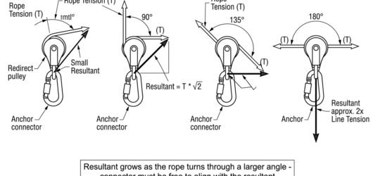 Vector diagram showing how the resultant force on a redirect pulley connector increases with the rope's angle Choosing Connectors for Hauling and Pulleys
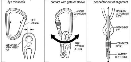 Three-panel line diagram of the pre-use check: measuring gate opening against the descender eye, confirming frChoosing a Connector for a Descender: Lockin
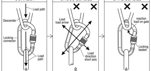 Line diagram comparing correct major-axis loading of a connector with a descender against cross-loading and gaChoosing a Connector for a Descender: Lockin
Lifting and rigging 35
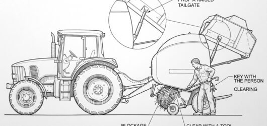 A baler pickup blocked with crop material, showing a person about to reach in crossed out, beside the same macBaling, Wrapping and Unblocking Machinery
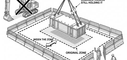 A load hanging from a jammed hook with a widened dashed exclusion boundary and barriers around it, adjacent plEmergency Response for a Suspended or Droppe
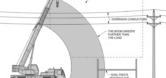 A crane beside overhead conductors with a large dashed exclusion volume around the lines, the boom slew arc drLifting Near Overhead Lines and Structures
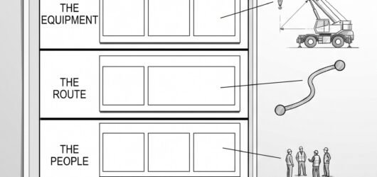 A single sheet divided into five stacked bands of empty boxes, each band linked by a leader line to a small skPlanning a Lift: What the Lift Plan Has to A
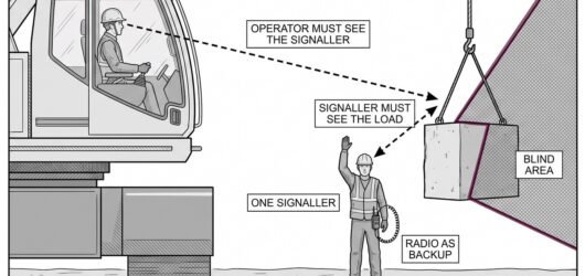 A crane operator in a cab with a dashed line of sight to a signaller standing clear of the load, with a secondSlinger and Signaller Communication for Lift
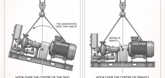 An asymmetric load shown suspended from a hook offset from its centre of gravity so it hangs tilted, beside thEstimating the Load and Finding the Centre o
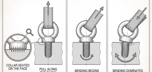 A collared eyebolt shown three times under an axial pull and at two increasing angles, with the bending momentEyebolts and Lifting Points: The Cost of Off
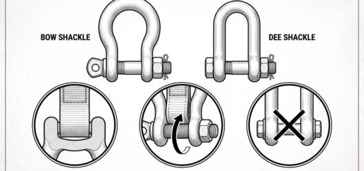 A bow shackle and a dee shackle side by side, with detail circles on a correctly seated sling in the bow, a slShackles: Selecting, Fitting and the Ways Th
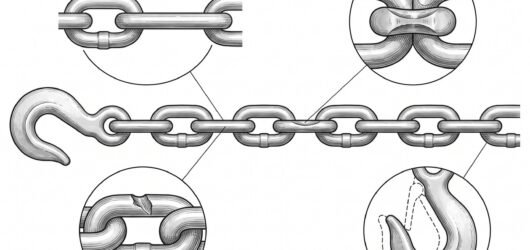 A run of chain with detail circles on a stretched link that will not articulate, wear at the link bearing poinChain Sling Discard Criteria and Safe Shorte
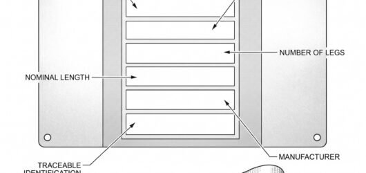 A sling identification label shown enlarged, with each field on it linked by a leader line to the part of the Reading a Sling Label and What the Working L
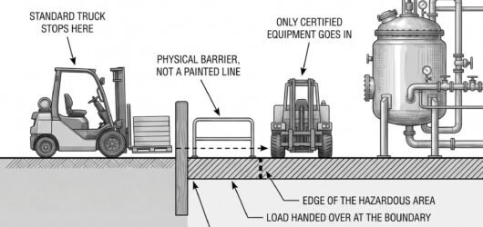 Simple line-art illustration of a small industrial forklift beside a boundary barrier at the entrance to a marMobile Equipment and Vehicles in Hazardous A
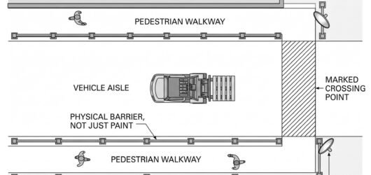 Simple line-art illustration of a warehouse floor with a barrier-separated pedestrian walkway alongside a forkForklift-Pedestrian Segregation and Warehous
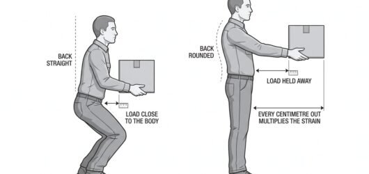 Simple line-art illustration of a worker lifting a box with bent knees and the load held close to the body.Back Support and Safe Lifting Technique
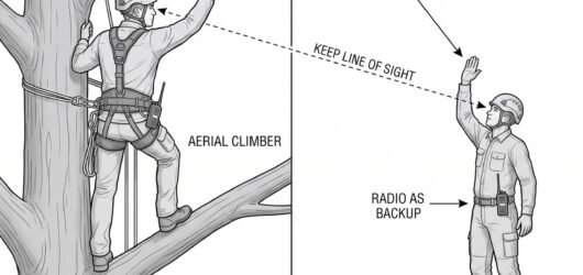 Simple line-art illustration of an aerial climber and a ground crew member exchanging a hand signal during a tGround-to-Aerial Communication During Tree F
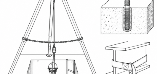 Correct tripod geometry: apex centred over the opening, equal leg spread, restraint chain taut, and the retrieVertical Extraction from a Confined Space: R
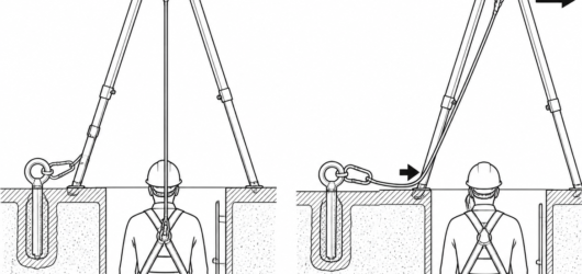 Correct (left) versus incorrect (right): an offset tripod side-loads the head, drags the line across the concrVertical Extraction from a Confined Space: R
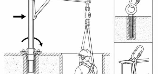 A davit arm places the lifting point over an offset or obstructed opening, but transfers a bending moment intoVertical Extraction from a Confined Space: R
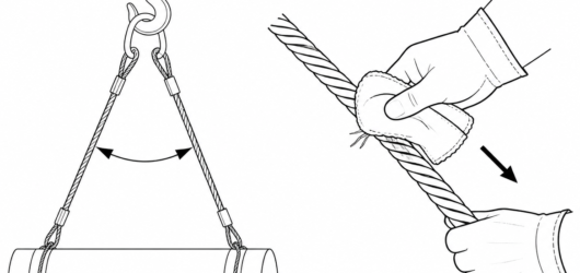 Correct method: sling uncoiled to full length, wiped clean, and a folded cloth drawn slowly along it in glovedWire Strop Inspection: What to Check Before
 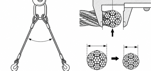 Measure across the crowns of two opposite strands with broad caliper jaws; a reduction of more than 10 % of noWire Strop Inspection: What to Check Before
 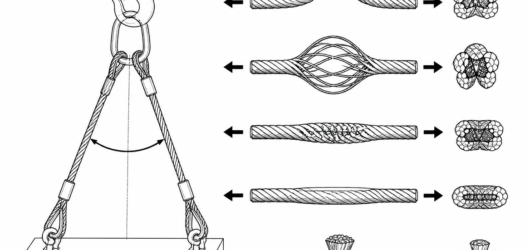 Each of these deformations is a withdrawal condition: kink, birdcaging, crushing or flattening, and core protrWire Strop Inspection: What to Check Before
 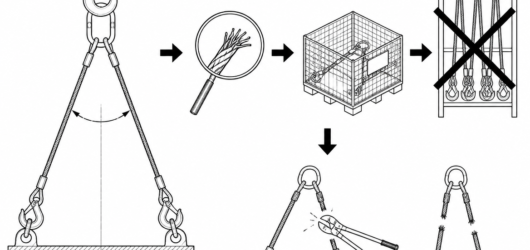 A withdrawn strop goes into physically separate quarantine, never back on the rack; where the decision is to sWire Strop Inspection: What to Check Before
 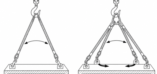 Two-point (left) resists lift-off only; four-point (right) with the rear junction low on the nape resists forwWearing a Helmet Without the Chinstrap: What
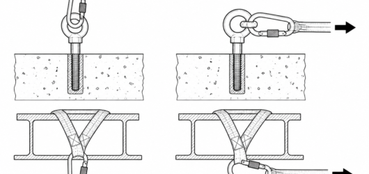 Correct: load in line with the spine, gate closed and locked . Incorrect: connector rotated so force presses aExamples of Dangerous Connector Loading: How
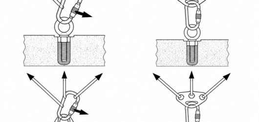 Three load paths in one connector force the gate outward; a rated multi-point plate keeps each load path indepExamples of Dangerous Connector Loading: How
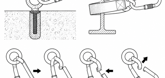 Roll-out sequence: an attachment point small enough to travel from the back of the throat to the gate can deprExamples of Dangerous Connector Loading: How
 A Class Q screw link is rated only with the barrel fully tightened and the frame gap completely bridged.Examples of Dangerous Connector Loading: How
 Incorrect: spare leg parked in the dorsal attachment point. Correct: spare leg on the designated keeper, whichExamples of Dangerous Connector Loading: How
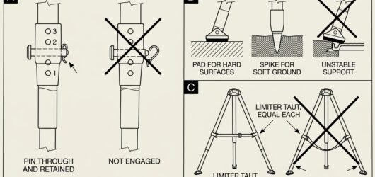 Comparison diagram of tripod leg pinning, foot types for hard and soft ground, and the difference between a taSetting Up a Tripod Over a Manhole: Footing,
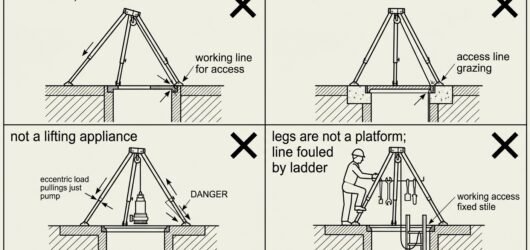 Four-panel diagram of common tripod setup errors over a manhole: tilted head, off-centre frame, use as a liftiSetting Up a Tripod Over a Manhole: Footing,
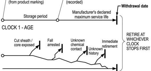 Diagram of two parallel timelines showing age-based service life from date of manufacture and condition-based Service Life and Retirement Criteria for Tex
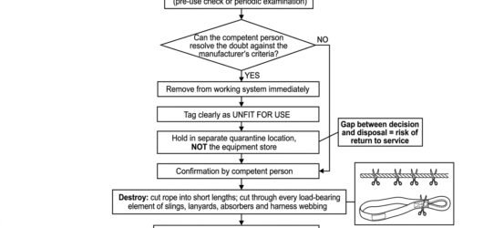 Flowchart of the textile retirement sequence from defect found through tagging, quarantine, competent person cService Life and Retirement Criteria for Tex
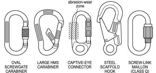 Reference diagram showing where certification markings are located on an oval screwgate, an HMS carabiner, a cReading the Markings on a Connector
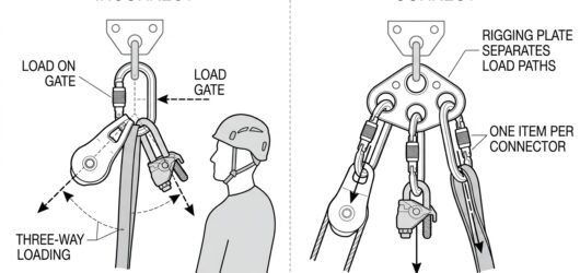 Diagram contrasting three-way loading of a single connector with a rigging plate that gives each component itsChoosing Connectors for Hauling and Pulleys
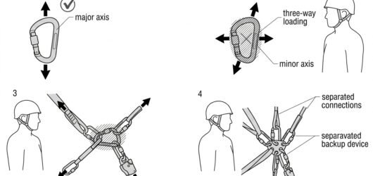 Diagram showing major-axis loading, minor-axis cross loading, three-way loading of one connector, and the corrChecking Connector Compatibility: A Field Me
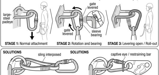 Three-stage diagram of connector roll-out on a large-radius padeye, with solutions shown using an interposed sChecking Connector Compatibility: A Field Me
Confined space 16
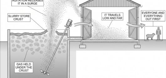 A section through a slurry store with a crust on the surface, gas shown collecting beneath it and surging upwaSlurry Gases and Confined Spaces on Farms
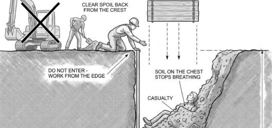 Section through a partly collapsed trench with a buried casualty, a rescuer at the crest not entering, spoil bRescue Planning for an Excavation or Structu
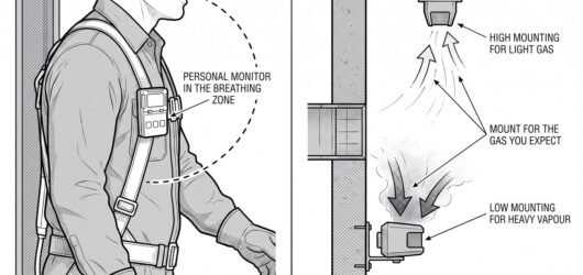 Simple line-art illustration of a portable multi-gas detector clipped to a worker's belt beside a wall-mountedGas Detection and Atmospheric Monitoring for
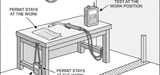 Simple line-art illustration of a portable gas detector positioned beside a welding torch on a work surface.Hot Work Permits in Explosive Atmospheres
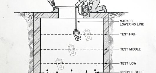 Simple line-art illustration of a gas detector being lowered on a cable into a confined space entry hatch to sConfined Space Chemical Hazards
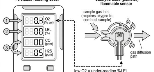 Diagram showing the atmospheric testing reading order – oxygen, then flammable gas, then toxic channels – and Atmospheric Testing Before Entry: Sequence,
 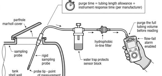 Remote sampling train for confined space atmospheric testing: probe, tubing, water trap, hydrophobic filter anAtmospheric Testing Before Entry: Sequence,
 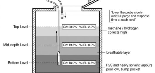 Cross-section of a vertical confined space showing stratified gas layers and probe sampling at top, mid-depth Atmospheric Testing Before Entry: Sequence,
 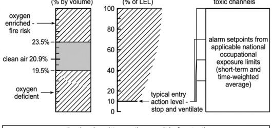 Chart of atmospheric testing action levels: acceptable oxygen band, flammable gas action line at ten percent LAtmospheric Testing Before Entry: Sequence,
 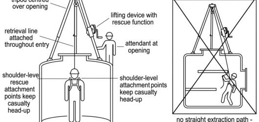 Cross-section diagram of a vertical confined space entry with a tripod and retrieval winch over the manway, coSelecting a Rescue Kit for the Task
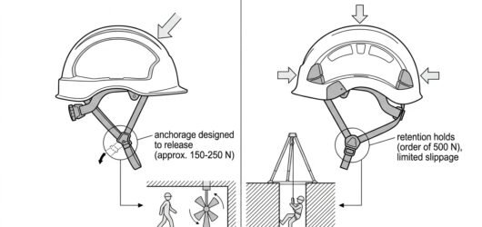 Diagram comparing EN 397 releasing chinstrap and EN 12492 retaining chinstrap, with confined space scenarios mSelecting a Helmet for Confined Space Work:
 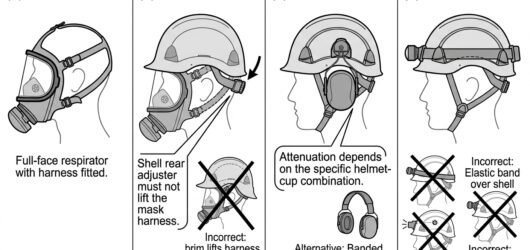 Four-step diagram of stacking respirator, helmet, hearing protection and headlamp for confined space entry, wiSelecting a Helmet for Confined Space Work:
 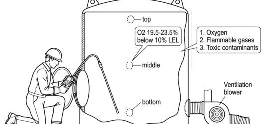 Technical diagram of a worker testing air quality with a probe at a confined space opening before entry, showiConfined Space Entry: The Permit Sequence, S
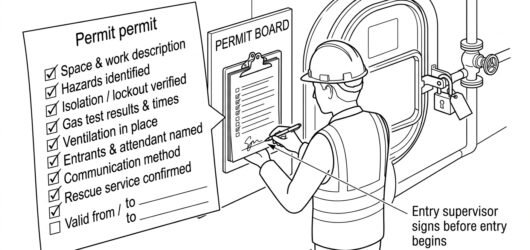 Technical diagram of an entry supervisor reviewing and signing a written confined space entry permit, checkingConfined Space Entry: The Permit Sequence, S
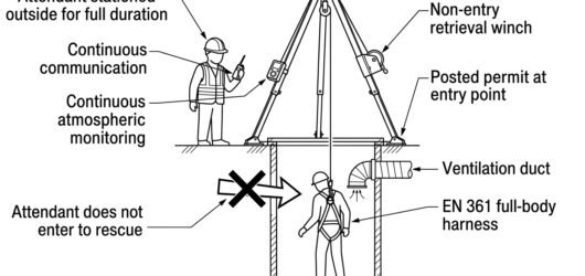 Technical diagram of an attendant stationed outside a confined space entry point, monitoring an entrant with aConfined Space Entry: The Permit Sequence, S
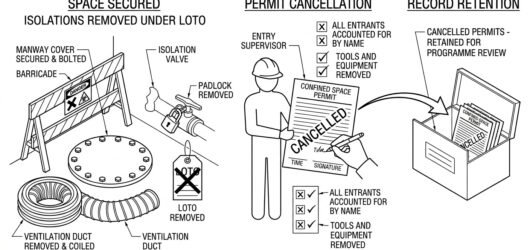 Technical diagram of confined space permit closeout: entrants accounted for, space secured, isolations removedConfined Space Entry: The Permit Sequence, S
Machinery and isolation 31
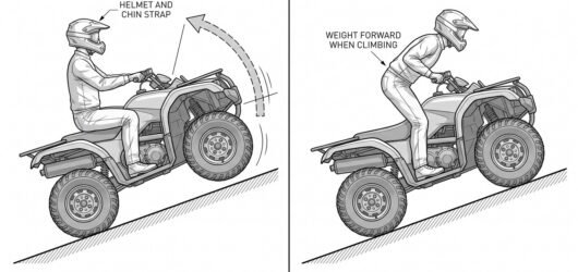 Two panels showing a quad bike on a slope: in the first the rider sits still and the machine tips, in the secoQuad Bikes and ATVs on Farms
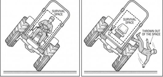 Two panels showing a tractor mid-overturn: in the first the belted operator stays within a dashed survival spaTractor Overturn: ROPS and Seat Belts
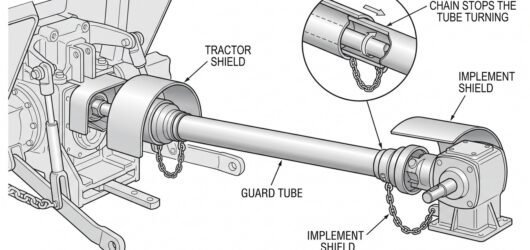 A tractor and implement connected by a PTO shaft shown from the side, with the tractor shield, the guard tube PTO Shafts: Guarding and Entanglement
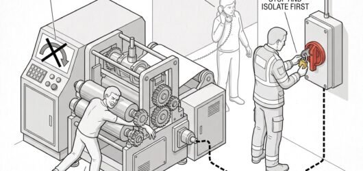 A machine with a casualty trapped at the mechanism, a first responder at the isolator fitting a lock rather thFirst Response to a Machine Entrapment
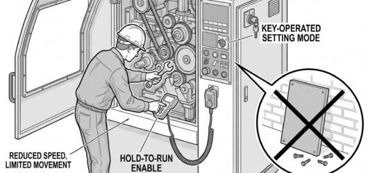 A machine with its guard open in a setting mode, a key-operated selector switch on the panel, and an operator Maintenance, Setting and the Guards That Com
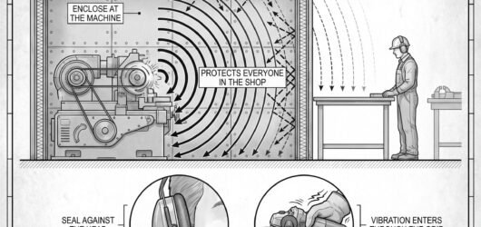 A machine shop section with a noisy machine enclosed and damped, sound paths drawn as curved lines reaching a Noise and Vibration in a Machine Shop
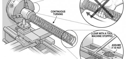 A lathe with a long continuous turning coiling off the workpiece, beside a detail circle of a hand grasping thSwarf, Chips and Hot Workpieces
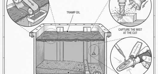 A machine tool sump in cutaway with a layer of tramp oil floating on top and metal fines settled at the bottomMetalworking Fluids: Mist, Dermatitis and Ta
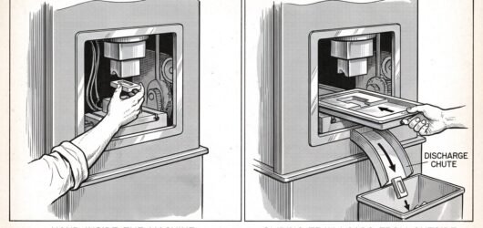 Two panels showing a hand reaching directly into a machine opening to place a workpiece, beside the same machiWhy Hands Enter Machines, and How to Stop Ne
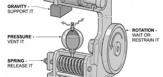 A machine cutaway with four stored energy sources marked: a raised ram held by a mechanical scotch, a charged Stored Energy: The Hazard That Survives Isol
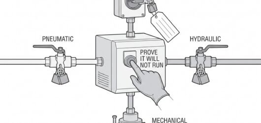 A machine with four isolation points marked around it – an electrical isolator, a pneumatic valve, a hydraulicIsolating Machinery: Locking Off Every Energ
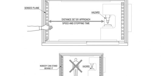 A plan view of a machine with a light curtain across its opening, a hand approaching through the beams, and a Light Curtains and Presence-Sensing Safeguar
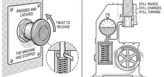 A mushroom-head emergency stop button with a detail circle showing it latched in and a twist arrow releasing iEmergency Stop: What It Does and What It Doe
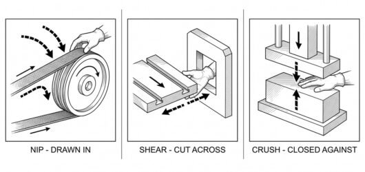 Three panels showing a nip point between a belt and pulley with arrows drawing material inward, a shear point Trapping Points: Nip, Shear and Crush
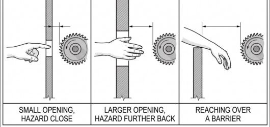 Three sections through a guard opening with a hand reaching in, showing a small opening with the hazard close,Safety Distances: Why Reach Decides the Guar
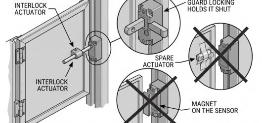 An interlocked guard with its actuator entering a switch, beside two detail circles showing a spare actuator tInterlocked Guards and How They Get Defeated
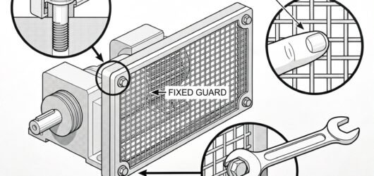 A fixed mesh guard bolted over a machine drive, with detail circles on a captive fastener retained in the guarFixed Guards and When They Are the Right Ans
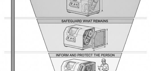 Three stacked bands showing the hierarchy of machine safeguarding, with the widest band at the top for eliminaThe Hierarchy of Machine Safeguarding: What
 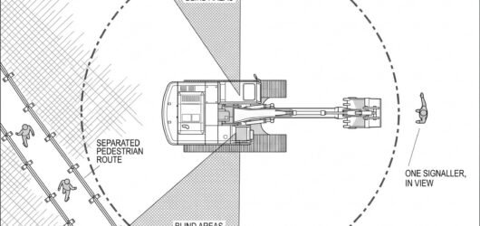 Plan view of an excavator with shaded blind areas around the machine, a slew radius circle marked, a barrieredWorking Near Mobile Plant: Exclusion Zones,
 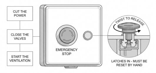 Simple line-art illustration of a mushroom-head emergency stop button on a wall-mounted enclosure beside a valEmergency Isolation and Shutdown Systems
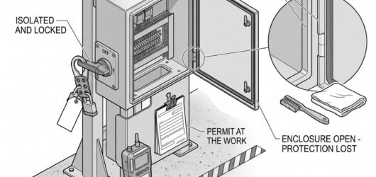 Simple line-art illustration of an opened equipment enclosure with a lockout padlock fitted to its isolator swMaintenance and Permit Work Inside Hazardous
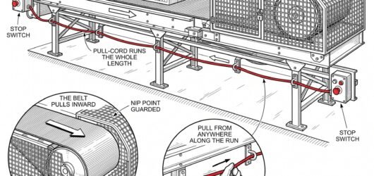 Simple line-art illustration of a conveyor belt with a pull-cord emergency stop running along its guarded sideConveyor Belt and Sortation System Safety
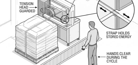 Simple line-art illustration of a strapping machine applying tensioned strap around a stacked pallet.Shrink Wrap and Strapping Machine Safety
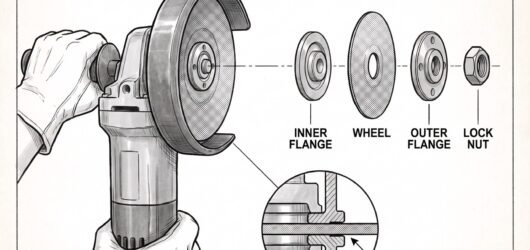 Simple line-art illustration of an angle grinder with its guard fitted, positioned beside a wheel and mountingGrinding and Cutting Wheel Safety
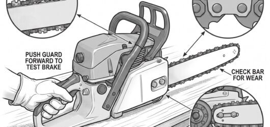 Simple line-art illustration of a hand testing a chainsaw's front hand guard and chain brake mechanism before Chainsaw Maintenance and Pre-Use Checks
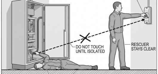 Simple line-art illustration of a rescuer reaching for a nearby isolation switch rather than directly touchingRescue Planning for an Electrical Contact In
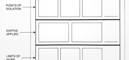 Simple line-art illustration of an electrical permit to work document with sections for equipment identificatiElectrical Permits to Work: What They Need t
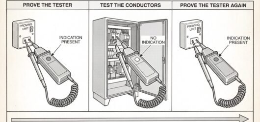 Simple line-art illustration of a voltage detector being touched to a known live test point, then to the isolaTesting for Absence of Voltage: The Sequence
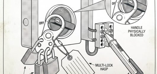 Simple line-art illustration of an electrical isolator switch with a padlock and a tag attached, next to a volLockout-Tagout for Electrical Isolation: Pro
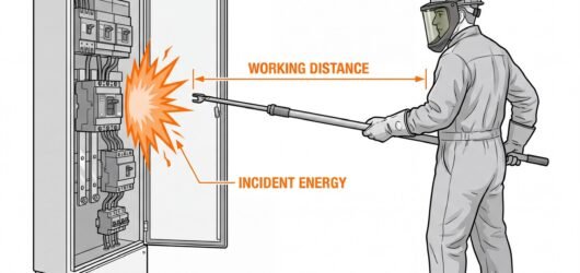 Side-view diagram of an open electrical switchgear panel with an arc flash burst at the panel face labelled inArc Flash Risk Assessment: Estimating Incide
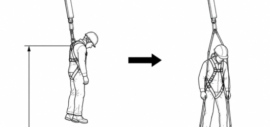 Suspension relief straps let the casualty stand and unload the leg straps while the rescue system is rigged; fRescuing a Person Hanging on an Energy Absor
Electrical 12
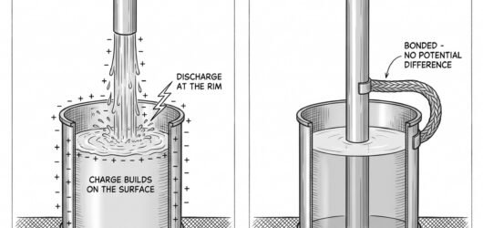 Simple line-art illustration of liquid flowing through a pipe into a container with a small spark shown at theStatic Electricity as an Ignition Source
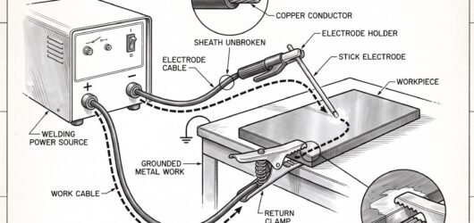 Simple line-art illustration of a welding electrode holder with intact cable insulation connected to a work reArc Welding: Electrical Hazards and Equipmen
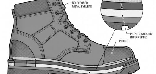 Simple line-art illustration of a safety boot with a sole cross-section showing a non-conductive layer, positiSelecting Footwear and Clothing for General
 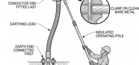 Simple line-art illustration of a temporary earthing clamp connected between a conductor and an earth point, pGrounding and Earthing for Temporary Electri
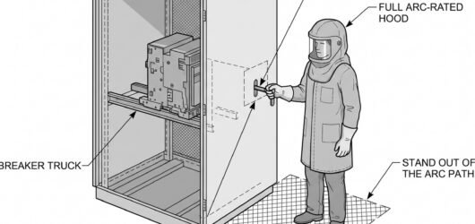 Simple line-art illustration of a technician in full arc-rated hood and clothing operating a switchgear rackinSwitchgear Operation: PPE and Procedure for
 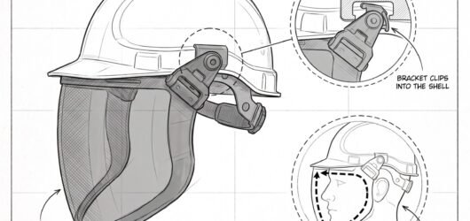 Simple line-art illustration of a safety helmet with an arc-rated face shield attached, covering the full faceSelecting a Helmet and Face Shield for Arc F
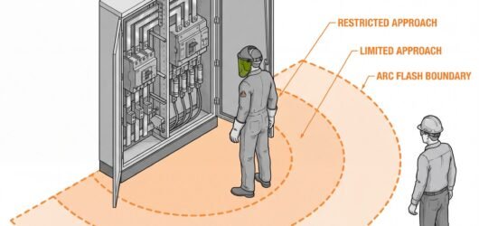 Isometric diagram of an open electrical switchgear panel with three dashed boundary arcs on the floor, labelleArc Flash Boundaries: Limited, Restricted an
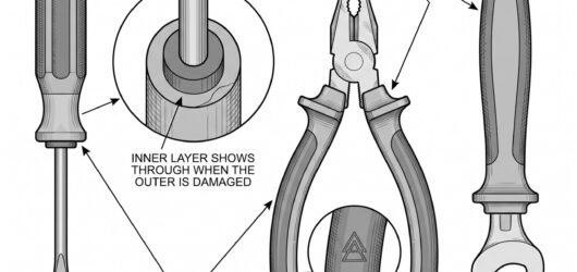 Simple line-art illustration of an insulated hand tool with its voltage rating marking visible on the handle, Insulated Tools for Electrical Work: What th
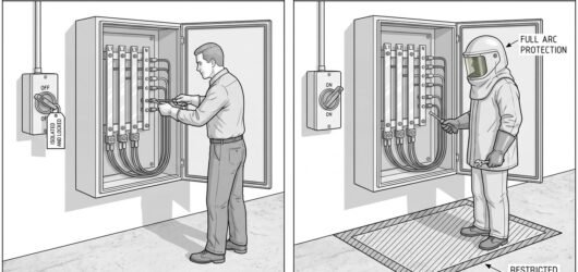 Simple line-art illustration comparing two electrical work scenarios: a technician working on a locked-off, taLive Working vs Dead Working: When Each Is J
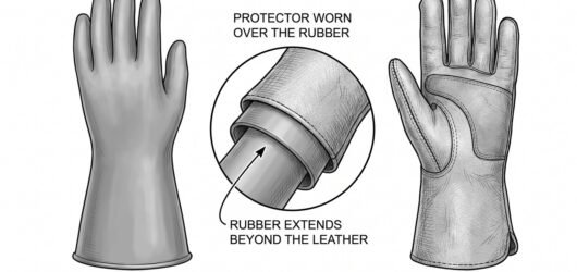 Simple line-art illustration of an insulating glove with a voltage class label, shown beside a separate leatheInsulating Gloves for Electrical Work: EN 60
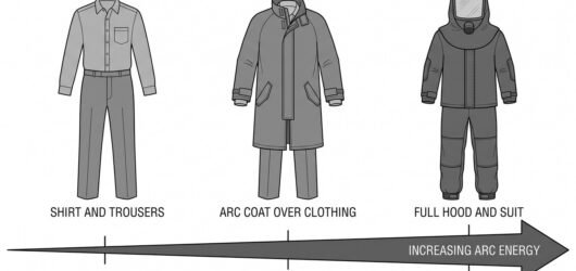 Simple line-art illustration of an arc-rated jacket with its label visible, positioned beside a separate generSelecting Arc-Rated Clothing: EN 61482 Expla
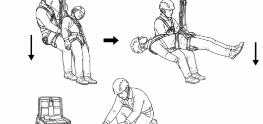 Current guidance (HSE Research Report RR708) does not support keeping a rescued casualty upright — lay them doAccompanied Descent Rescue: How the Manoeuvr
Excavation and groundwork 2
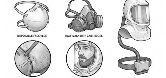 Three respiratory options side by side – a disposable filtering facepiece, a half mask with a cartridge, and aRespiratory Protection for Agricultural Dust
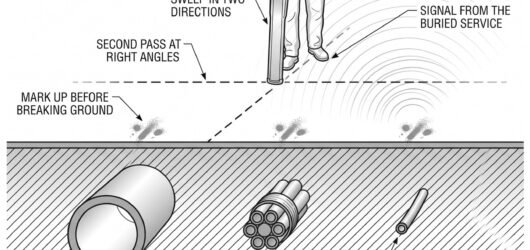 Simple line-art illustration of a person using a cable avoidance detection tool to sweep the ground above a maUnderground Cable Strikes: Locating and Avoi
PPE and health 43
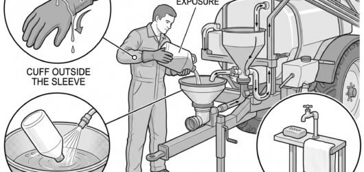 An operator at a sprayer induction bowl pouring concentrate from a container, with detail circles showing a glPesticide Handling: Mixing and Loading
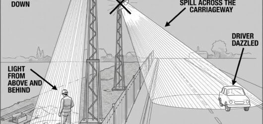 A section through a night works showing a floodlight on a mast aimed down into the works area with a shielded Night Working: Lighting the Works Without Da
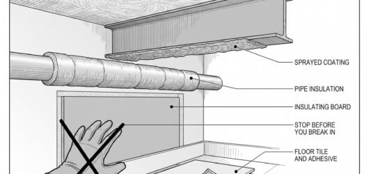 Cutaway of a building interior with leader lines to pipe lagging, sprayed coating on a steel beam, an insulatiAsbestos: Recognising It and Stopping Before
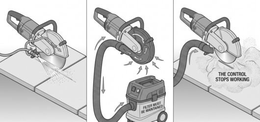 A cut-off saw shown twice, once with a water feed at the blade and once with an extraction shroud and hose, wiControlling Silica Dust When Cutting, Chasin
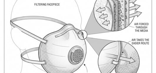 A filtering facepiece shown in cutaway with the filter media and exhalation valve, beside a face-seal detail sRespiratory Protection for Silica and Constr
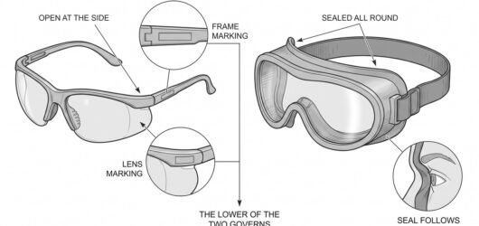 Safety spectacles and goggles shown side by side with the frame marking and the lens marking enlarged in two dEye Protection on a Construction Site: Impac
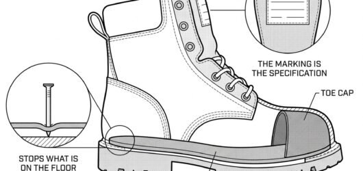 Cutaway of a safety boot showing the toe cap, the penetration-resistant midsole and the cleated outsole, with Safety Footwear for Construction: Reading th
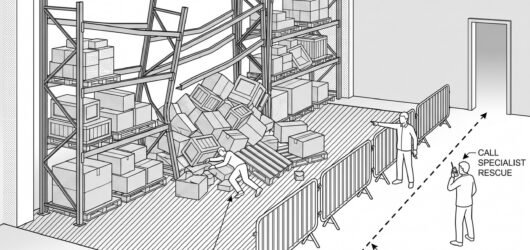 Simple line-art illustration of a rescue team assessing a partially collapsed racking structure with a barrierTrapped or Crushed Worker Rescue Planning in
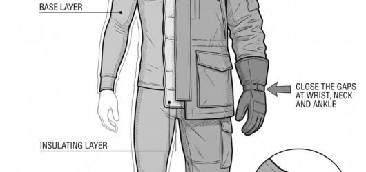 Simple line-art illustration of a worker in layered cold-store clothing with insulated gloves and a hood.Cold Store and Freezer Warehouse PPE
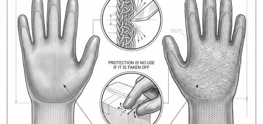 Simple line-art illustration of a cut-resistant glove with a textured grip palm and knitted cuff.Manual Handling Gloves and Cut Protection fo
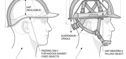 Simple line-art illustration of a lightweight bump cap with a peaked brim and internal padded liner.Bump Caps versus Safety Helmets: EN 812
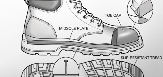 Simple line-art illustration of a safety boot with a reinforced toecap and slip-resistant sole tread.Safety Footwear for Warehouse and Logistics
 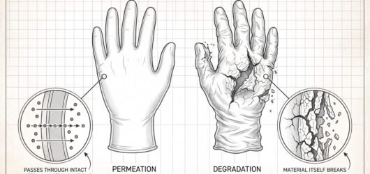 Simple line-art illustration of two gloved hands, one glove shown as a cutaway revealing chemical molecules diPermeation versus Degradation: Choosing Glov
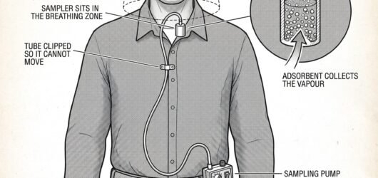 Simple line-art illustration of a personal air sampling pump clipped to a worker's belt with a sampling tube rChemical Exposure Monitoring and Health Surv
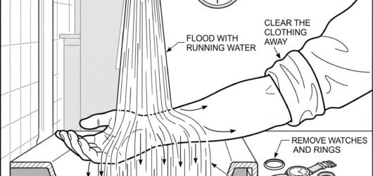 Simple line-art illustration of a hand held under a stream of running water at an emergency eyewash station.Corrosive Chemical Burns: First Aid and Imme
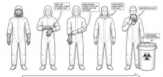 Simple line-art illustration of a person removing a chemical protective glove by peeling it inside-out over thPPE Doffing and Personal Decontamination Seq
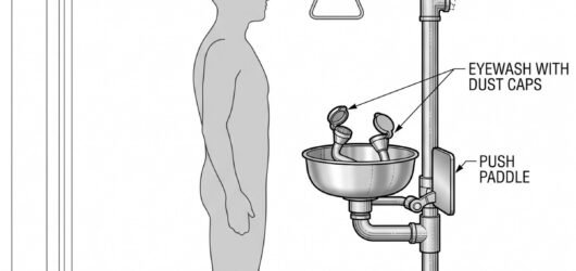 Simple line-art illustration of a combined emergency shower and eyewash station with a pull-handle and hands-fDecontamination: Emergency Showers and Eyewa
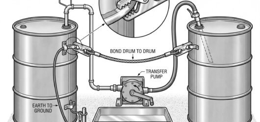 Simple line-art illustration of a transfer pump connected between two chemical containers with a bonding cableChemical Transfer and Pump Safety
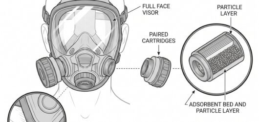 Simple line-art illustration of a full face respirator mask with a screw-in gas cartridge on each side.Respiratory Protection for Chemical Vapours
 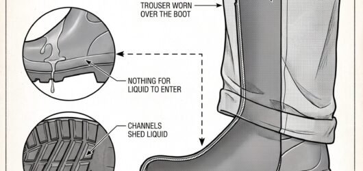 Simple line-art illustration of a seamless rubber chemical-resistant boot with a pull-on design.Chemical-Resistant Footwear
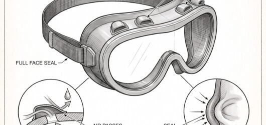 Simple line-art illustration of a pair of sealed chemical splash goggles with indirect ventilation ports.Eye and Face Protection for Chemical Splash
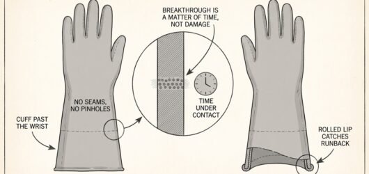 Simple line-art illustration of a chemical-resistant gauntlet glove with a long cuff, laid flat.Selecting Chemical-Resistant Gloves to EN 37
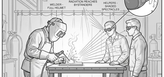 Simple line-art illustration of a pair of shaded safety glasses positioned in front of a welding work area.Eye and Face Protection for Bystanders and H
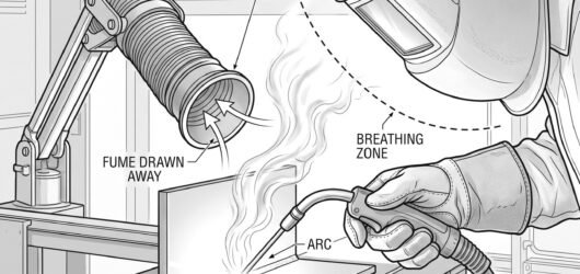 Simple line-art illustration of a welder using a torch fitted with a local fume extraction nozzle near the welRespiratory Protection for Welding Fume
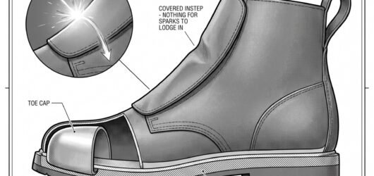 Simple line-art illustration of a pull-on welding boot with a covered lace flap and reinforced toe.Safety Footwear for Welding and Hot Work
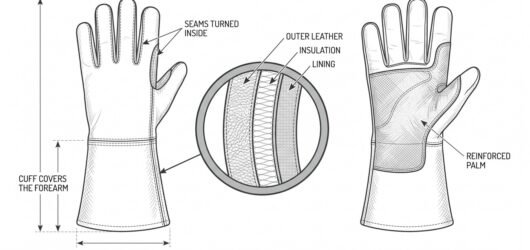 Simple line-art illustration of a gauntlet-style welding glove with an extended cuff and reinforced palm.Selecting Welding Gloves to EN 407
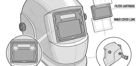 Simple line-art illustration of a welding helmet with a rectangular auto-darkening filter lens mounted in the Welding Helmets and Auto-Darkening Filters:
 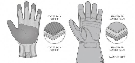 Simple line-art illustration of two work gloves side by side with clear spacing: a general mechanical-protectiSelecting Gloves for Grounds and Tree Care W
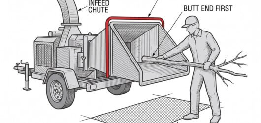 Simple line-art illustration of an operator feeding a branch into a wood chipper from the side, standing well Chipper Safety: Feed Zone Hazards and Safe O
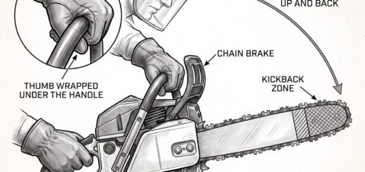 Simple line-art illustration of a chainsaw bar with the upper tip kickback zone highlighted, held with a firm Chainsaw Kickback: What Causes It and How PP
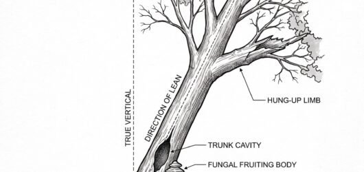 Simple line-art illustration of a tree with a visible lean, a cracked branch caught in the upper canopy, and aAssessing a Tree Before Felling: Lean, Hang-
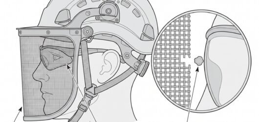 Simple line-art illustration of a pair of wraparound safety glasses positioned beneath a helmet-mounted mesh vEye and Face Protection for Tree Care Work
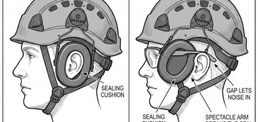 Simple line-art illustration of a pair of ear defenders mounted on articulated arms attached to a helmet shellHearing Protection for Chainsaw and Power To
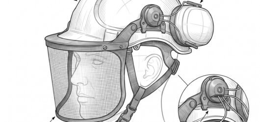 Simple line-art illustration of a forestry safety helmet with integrated ear defenders and a mesh visor attachChoosing a Helmet System for Chainsaw and Gr
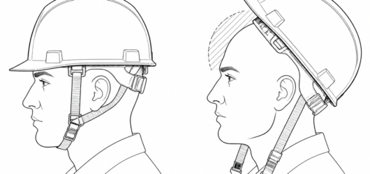 Correct (left): shell level, brow covered, chinstrap fastened snug. Incorrect (right): shell tipped back on thWearing a Helmet Without the Chinstrap: What
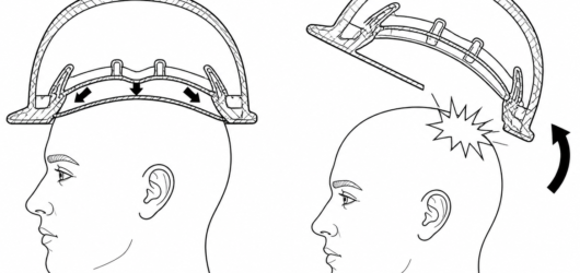 Retained (left): the crown takes the load and the suspension deforms as designed. Unretained (right): the shelWearing a Helmet Without the Chinstrap: What
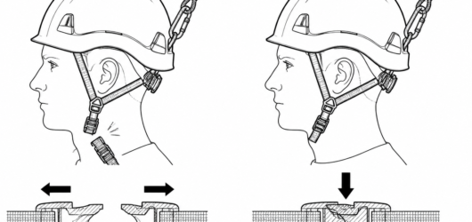 EN 397 (left): the strap releases at 150–250 N so a snag cannot load the neck. EN 12492 (right): the strap musWearing a Helmet Without the Chinstrap: What
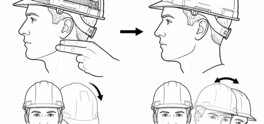 Tension check: roughly two fingers' thickness of slack, strap snug under the jaw — then confirm with a nod-andWearing a Helmet Without the Chinstrap: What
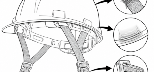 Withdraw from service: frayed or abraded webbing, glazing from heat, and any cracked or rounded buckle latch aWearing a Helmet Without the Chinstrap: What
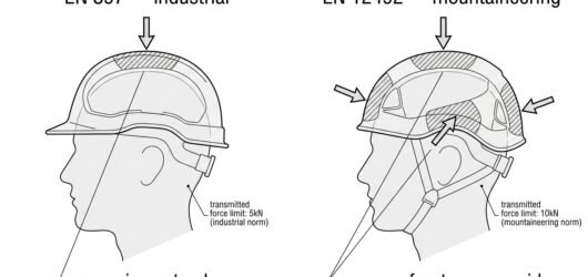 Diagram comparing helmet impact test zones: EN 397 tests crown impact only, EN 12492 tests crown, front, rear Helmet Standards: EN 397 and EN 12492
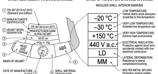 Annotated helmet label showing standard number, size range, mass, date of manufacture and optional EN 397 perfHelmet Standards: EN 397 and EN 12492
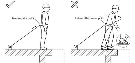 Comparison diagram of a restraint tether routed from the rear belt point versus a lateral point, showing the lWhich Attachment Points to Use for Restraint
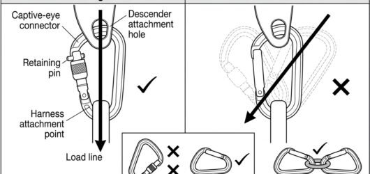 Diagram showing a captive-eye connector and retaining pin keeping load on the spine versus a free-rotating conConnector Basics: Gates, Axes and Loading
Vehicles and plant 13
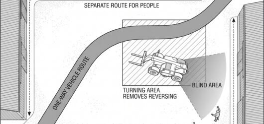 A farmyard plan view with a one-way vehicle route marked by arrows, a separate pedestrian route along the builVehicles, Yards and Reversing on the Farm
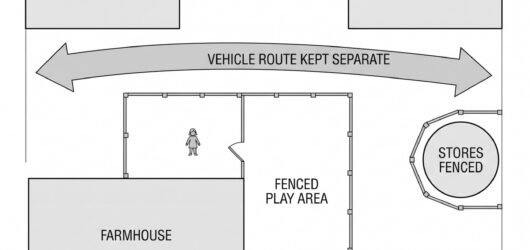 A farmyard plan view with a fenced play area beside the house, a separate vehicle route through the yard markeChildren and Visitors on a Working Farm
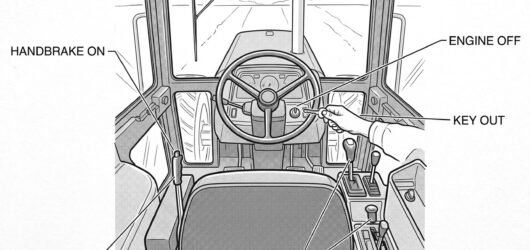 A tractor cab interior seen from behind the seat with four numbered actions marked in sequence: the handbrake Safe Stop: The Routine Before You Leave the
 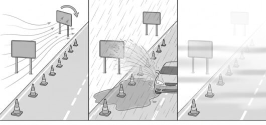 Three panels showing the same roadside layout in wind with a sign turning, in heavy rain with spray from a pasWeather on the Roadside: Wind, Rain, Fog and
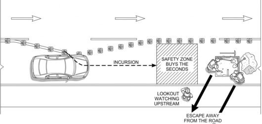 A plan view of a closure with a vehicle crossing the taper into the closed lane, the safety zone hatched aheadVehicle Incursion: Planning for the Driver W
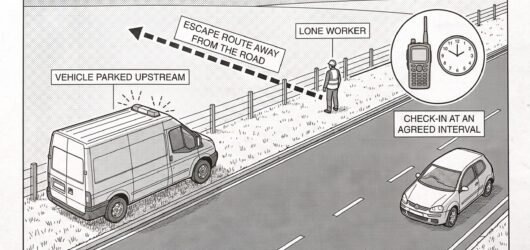 A lone worker at a roadside verge with a vehicle parked upstream as a buffer, a dashed escape route running awLone Working and Roadside Patrols
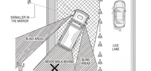 A plan view of a works vehicle reversing inside a closure with shaded blind areas behind and along the offsideReversing and Manoeuvring Plant on a Live Ro
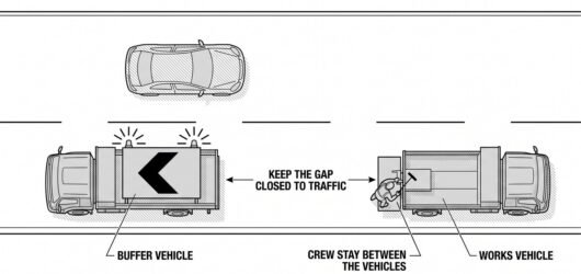 A works vehicle with a directional arrow board and beacons travelling along a lane with a second buffer vehiclMobile and Short-Duration Works on a Live Ro
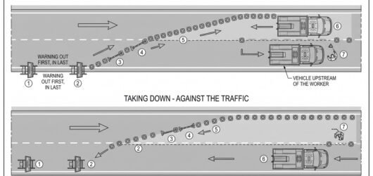 A plan view showing a works vehicle placing cones with a numbered sequence running in the direction of trafficSetting Out and Taking Down a Traffic Manage
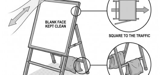 A temporary sign on a frame at the roadside seen from a driver approaching, with a detail of the sign turned sTemporary Signs: Placement, Legibility and S
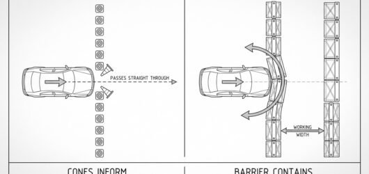 Two panels showing a vehicle striking a line of cones and passing straight through, beside a vehicle striking Cones, Barriers and What Actually Stops a Ve
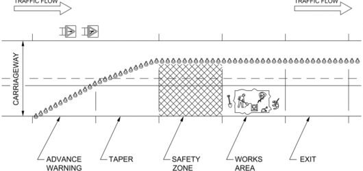 A plan view of a lane closure showing the advance warning area, the taper, the safety zone, the works area andThe Anatomy of a Temporary Traffic Managemen
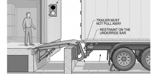 Simple line-art illustration of a mechanical wheel chock positioned against a trailer tire at a loading dock.Loading Dock Safety and Vehicle Restraint Sy
Agriculture 3
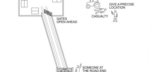 A farm plan view with the house, a field where a casualty lies, a marked access route from the road with two gEmergency Response on a Remote Holding
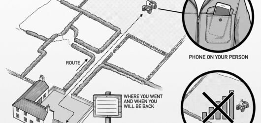 A farm plan view with a house at one side and several fields, a marked route from the yard to a distant field,Lone Working on a Farm
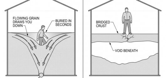 A section through a grain bin showing a person on the surface being drawn into a funnel of flowing grain towarGrain Stores and Flowing Grain Entrapment
Other subjects 53
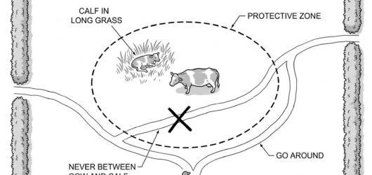 A field plan view showing a cow and calf with a dashed protective zone around them, a person walking a path thBulls, Cows With Calves and the Animals That
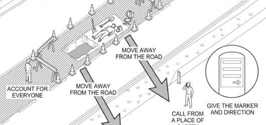 A roadside incident with arrows showing the crew moving away from the carriageway behind a barrier, a figure aEmergency Response and Evacuation From a Liv
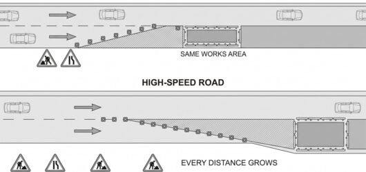 Two plan views of the same lane closure drawn to the same scale, one on a slow road with short advance signingHigh-Speed Roads: What Changes
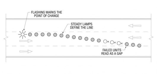 A plan view of a taper at night with steady lamps drawn as small filled circles along the closure line and a fLamps, Beacons and Warning Lights on a Works
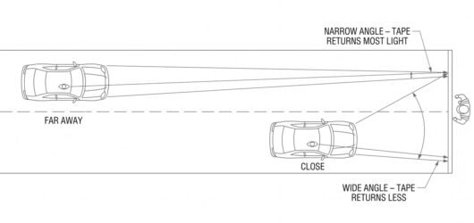 A car approaching a worker at night with the headlight beam and the driver's line of sight drawn as two lines Being Seen at Night: Retroreflection and Hea
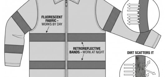 A high-visibility coat shown flat with the fluorescent panels and the retroreflective bands distinguished, besKeeping High-Visibility Clothing Effective:
 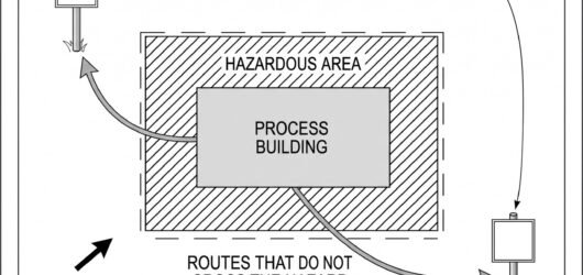 Simple line-art illustration of an assembly point marker post on open ground with a building outline in the baExplosion and Fire Emergency Response Planni
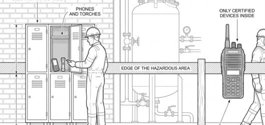 Simple line-art illustration of a mobile phone and a small torch placed in a storage locker outside a marked aPersonal Electronic Devices and Ignition Sou
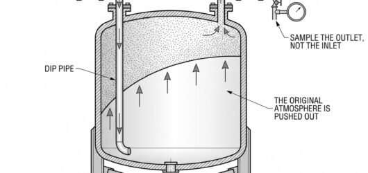 Simple line-art illustration of a storage vessel with an inert gas supply line entering at the top and a vent Purging and Inerting Procedures
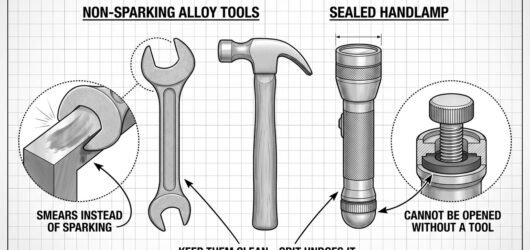 Simple line-art illustration of a non-sparking bronze wrench beside a handheld intrinsically safe torch.Non-Sparking Tools and Intrinsically Safe Eq
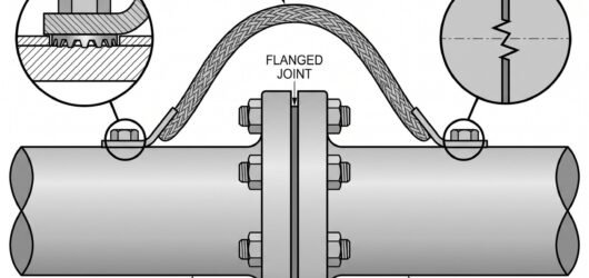 Simple line-art illustration of a bonding strap connected across a flanged pipe joint between two pipe sectionGrounding and Bonding for Fixed Equipment an
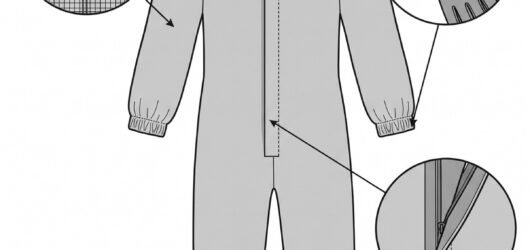 Simple line-art illustration of a one-piece antistatic coverall with a zip closure and elasticated cuffs.Selecting Antistatic and Flame-Resistant Clo
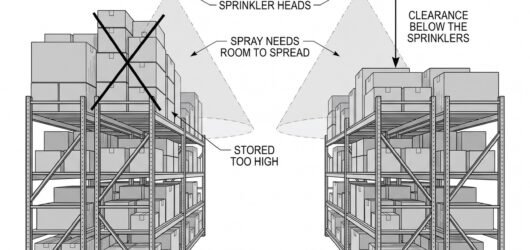 Simple line-art illustration of a warehouse aisle with clear space maintained between racking rows and a sprinWarehouse Fire Safety and Storage Configurat
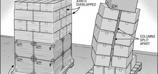 Simple line-art illustration of stacked pallets with heavier boxes at the base and progressively lighter boxesSafe Stacking and Load Securing for Storage
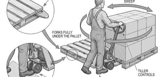 Simple line-art illustration of a pallet truck with its forks lowered under a pallet on a level floor.Safe Use of Pallet Trucks and Hand Trucks
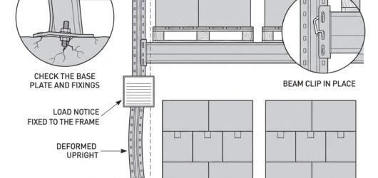 Simple line-art illustration of a warehouse racking upright with a visible bend near its base, next to an undaRacking Inspection and Load Limits
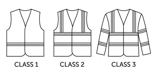 Technical line-art diagram comparing three high-visibility garments: a Class 1 vest with a single reflective bHi-Vis Clothing Classes: EN ISO 20471 Explai
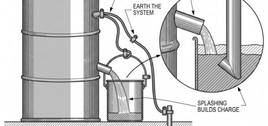 Simple line-art illustration of two metal drums connected by a bonding cable, with a separate grounding cable Flammable Liquid Handling and Static Control
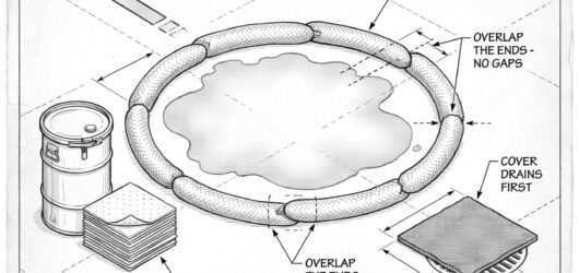 Simple line-art illustration of absorbent spill socks laid in a ring around a small chemical spill on a floor.Spill Response and Containment
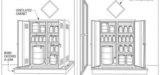 Simple line-art illustration of two chemical storage cabinets separated by a solid physical partition wall.Chemical Storage: Segregation and Incompatib
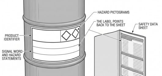 Simple line-art illustration of a chemical drum with a diamond-shaped hazard symbol and a flame symbol printedSafety Data Sheets and Hazard Communication
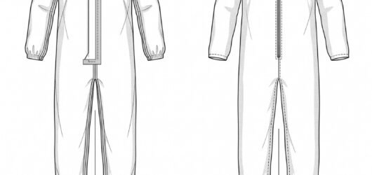 Simple line-art illustration of a one-piece chemical protective coverall with a sealed hood and elasticated cuChemical Protective Clothing: EN 14605 versu
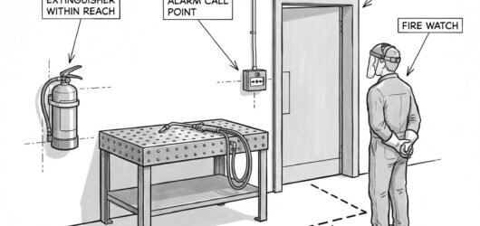 Simple line-art illustration of a fire extinguisher and an alarm call point mounted on a wall near a hot work Fire Response and Emergency Planning for Hot
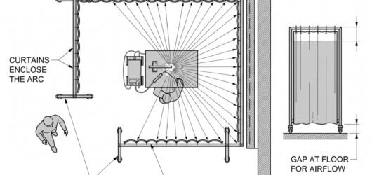 Simple line-art illustration of a flame-resistant welding curtain hung on a frame enclosing a work area, extenWelding Screens and Curtains for Bystander P
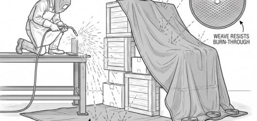 Simple line-art illustration of a fire-resistant welding blanket draped over combustible material near a work Spark and Slag Control: Housekeeping for Hot
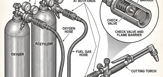 Simple line-art illustration of an oxy-fuel cutting torch with flashback arrestors fitted at the hose connectiOxy-Fuel Cutting Hazards
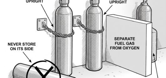 Simple line-art illustration of gas cylinders secured upright by a chain against a wall bracket, protective caGas Cylinder Handling and Storage for Weldin
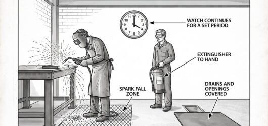 Simple line-art illustration of a fire extinguisher positioned beside a welding work area with a covered floorHot Work Permits and Fire Watch
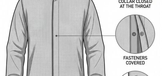 Simple line-art illustration of a flame-resistant welding jacket with a stand-up collar and covered front closFlame-Resistant Welding Clothing: EN ISO 116
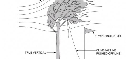 Simple line-art illustration of a tree canopy swaying in wind with a small wind-speed indicator flag beside itWeather Limits for Tree Work: Wind and Its E
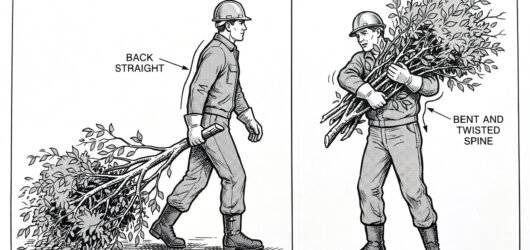 Simple line-art illustration of a worker dragging a brash branch by the butt end while walking forward, keepinBrash and Debris Handling: Manual Handling R
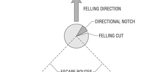 Simple line-art illustration of a tree with two diagonal escape route paths marked leading away from the anticFelling Cuts: Planning the Escape Route Befo
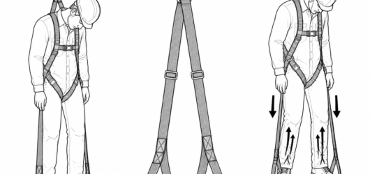 Suspension relief straps deployed: standing in the loops unloads the thigh straps and lets the calf muscles reSuspension Trauma: Why Minutes Matter
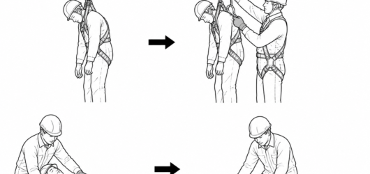 After release, manage the casualty by standard first aid principles and lay them flat as their condition requiSuspension Trauma: Why Minutes Matter
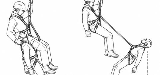 Left: rescue link adjusted short, casualty's chest below the rescuer's, head supported. Right: link too long —Accompanied Descent Rescue: How the Manoeuvr
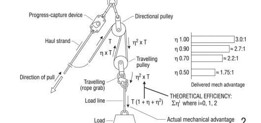 Schematic 3:1 hauling system with strand tensions labelled T, eta T and eta squared T, alongside a bar chart oPulley Efficiency: What the Numbers Mean
 Diagram of a locking carabiner spine with callouts identifying manufacturer, model, EN 362 standard and class Reading the Markings on a Connector
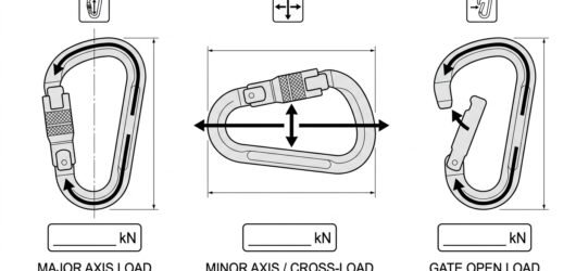 Three-panel diagram showing the major-axis, minor-axis and gate-open loading pictograms marked on connectors, Reading the Markings on a Connector
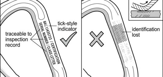 Comparison diagram of a carabiner with legible markings versus one whose serial number and class letter have bReading the Markings on a Connector
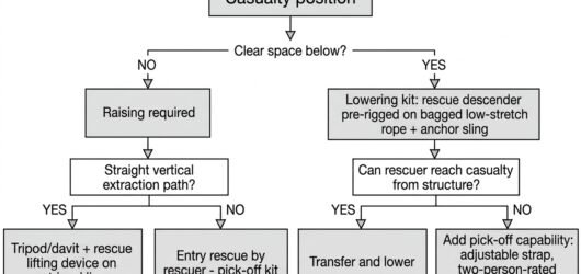 Decision flow diagram showing how casualty position, clear space below and extraction path determine whether tSelecting a Rescue Kit for the Task
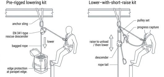 Side-by-side diagram comparing a pre-rigged lowering kit with a lower-and-short-raise kit including a small haSelecting a Rescue Kit for the Task
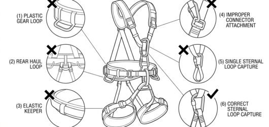 Diagram marking gear loops, haul loop, strap keepers, adjusters and a single sternal loop as points that must Which Attachment Points to Use for Restraint
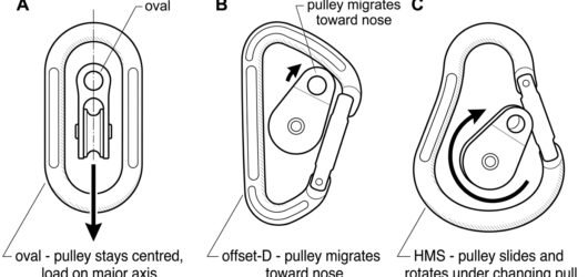 Diagram comparing oval, offset-D and pear-shaped connectors in a pulley attachment hole, showing how each shapChoosing Connectors for Hauling and Pulleys
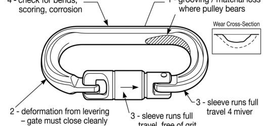 Inspection diagram of a hauling connector showing wear groove at the pulley bearing surface, nose deformation,Choosing Connectors for Hauling and Pulleys
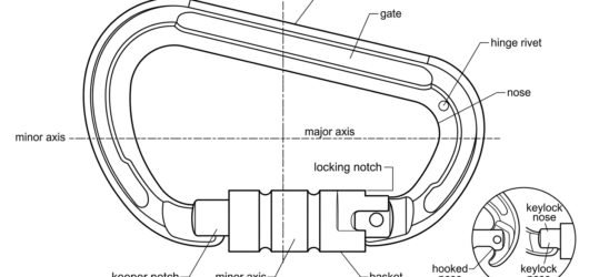 Labelled line diagram of a locking connector showing spine, gate, hinge, nose, keeper, locking sleeve and baskConnector Basics: Gates, Axes and Loading
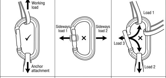 Three-panel diagram comparing correct major-axis loading with cross-loading on the minor axis and three-way loConnector Basics: Gates, Axes and Loading
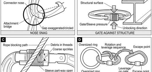 Four-panel diagram of gate-open failure modes: nose snag, gate pressed against structure, blocked locking sleeConnector Basics: Gates, Axes and Loading
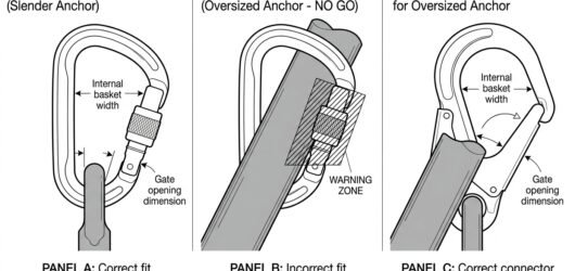 Three-panel diagram comparing correct basket seating, a connector forced onto a large bar and bearing on the gChecking Connector Compatibility: A Field Me
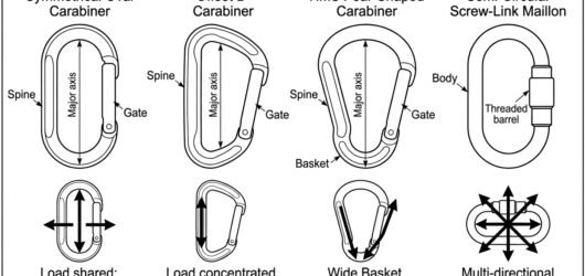 Comparison diagram of oval, offset D, HMS pear and semi-circular maillon connectors with arrows showing how eaConnector Shapes and Where Each Belongs
 Diagram of an HMS pear connector used correctly with a hitch and second connector, plus cross-loading and gateConnector Shapes and Where Each Belongs
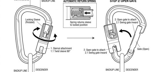 Line diagram of a two-stage auto-locking connector showing the sleeve being twisted and then the gate pushed oConnector Locking Systems Compared: Screw-Lo
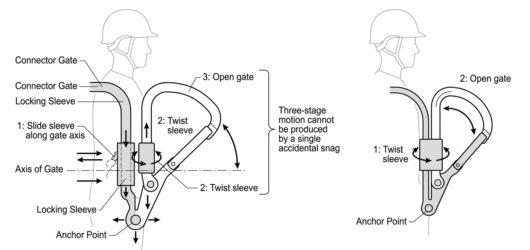 Comparison diagram of a three-stage auto-locking connector requiring slide, twist and open, alongside a simpleConnector Locking Systems Compared: Screw-Lo
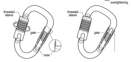 Line diagram of a manually threaded screw-lock connector showing the sleeve being wound down until it seats agConnector Locking Systems Compared: Screw-Lo