Safety / Tips and Tricks / Rope access and confined space
Activity 01 · Rope access
Heavy Load Lowering Anchor: Rigging and Controlling 150 kg to 250 kg from a Single Point
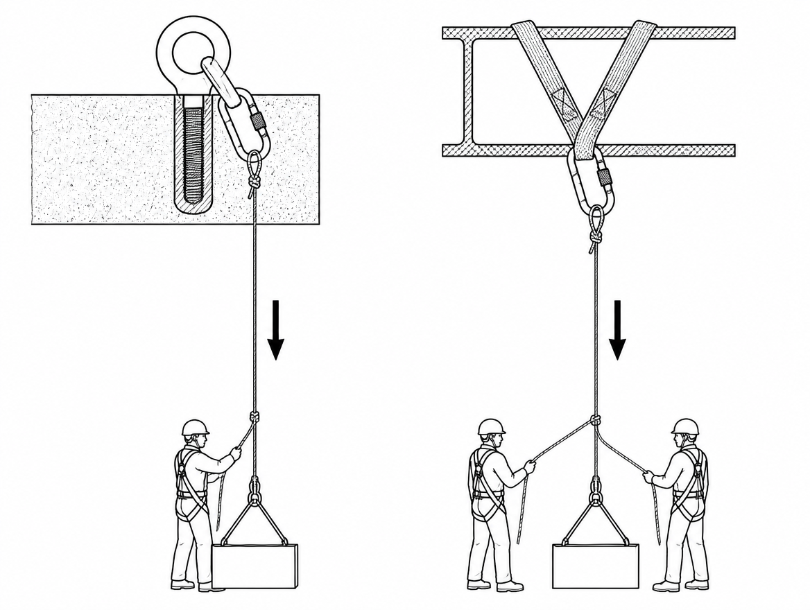
A 200 kg load on a lowering line is not simply twice as demanding as a 100 kg load. Somewhere between one person and two, the operation leaves the certification envelope that most personal fall protection equipment was tested in. Two-person rescue loads (casualty plus attendant), a basket stretcher with its rigging, a submersible pump coming out of a wet well, a valve actuator off a gantry — these routinely land in the 150 kg to 250 kg band, where single-person descenders, portable anchor devices and tripods are no longer covered by their own instructions. A heavy load lowering anchor has to be selected, verified and rigged on different arithmetic.
First decision: is this a person load or a material load?
The regulatory route determines which ratings apply, and mixing the two is the most common source of confusion on site.
- Person load (rescue, suspended access, controlled descent of a casualty): personal protective equipment under Regulation (EU) 2016/425, with harmonised standards such as EN 795 for anchor devices, EN 341 for descender devices for rescue, EN 1496 for rescue lifting devices, EN 1891 for low-stretch kernmantle rope and EN 362 for connectors. Ratings are expressed as a rated load or a number of persons, and strength requirements are expressed directly in kilonewtons.
- Material load (equipment, plant, spoil, a tool package): lifting equipment and lifting accessories under Directive 2006/42/EC, with in-service inspection obligations flowing from national implementations of Directive 2009/104/EC. Ratings are expressed as a working load limit (WLL) with a design factor already built in — typically 7:1 for textile slings to EN 1492-1 and EN 1492-2, 4:1 for chain slings to EN 818-4, 5:1 for wire rope slings to EN 13414-1.
A 250 kg motor lowered on PPE-rated rope through a PPE descender is not a compliant lifting operation, and a chain hoist rated 500 kg WLL is not automatically acceptable for lowering a person. Where a load contains both — a stretcher with an attendant — the person-load framework governs, and every component in the system must be rated for the combined mass declared by its manufacturer.
What the anchor actually sees is not the mass of the load
Start with static weight, then add the multipliers.
- 150 kg ≈ 1.47 kN
- 200 kg ≈ 1.96 kN
- 250 kg ≈ 2.45 kN
Those figures look comfortable against the 12 kN static strength requirement EN 795:2012 places on a metal anchor device — until the geometry is included. A rope that runs up to a pulley at the anchor and back down to a brake operator turns the anchor into a redirect: both rope legs pull downwards, and the anchor carries roughly twice the load, plus the friction component. A 250 kg load through a 180° redirect puts on the order of 5 kN into that single point before anything unexpected happens.
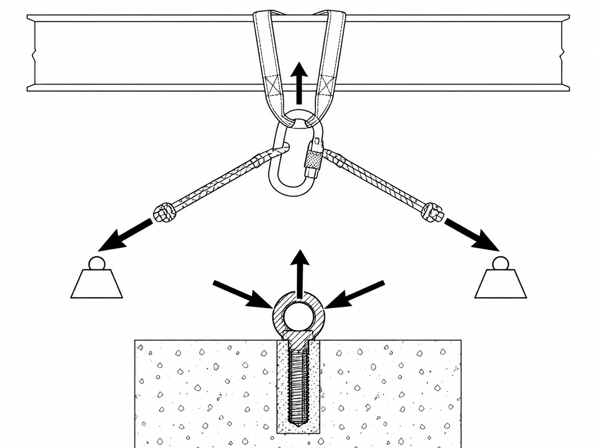
Then add the dynamic component. Snatching the load off a ledge, an abrupt stop at the brake, a shock as a sling comes tight or a load shifts — each can double the force momentarily. That is why EN 795:2012 is written around a single person and why CEN/TS 16415 exists at all: it sets out the requirements for anchor devices intended for use by more than one person at the same time, with increased test loads. If a 200 kg two-person load is planned, the anchor device selected has to be declared by its manufacturer for multi-person or heavy-load use — an EN 795 Type B tripod or Type E deadweight anchor tested for one person is outside its scope and outside its instructions.
Selecting the anchor: device rating and structure rating are two separate checks
EN 795:2012 classifies anchor devices as Type A (structural anchors), Type B (portable, temporary), Type C (flexible horizontal anchor line), Type D (rigid rail) and Type E (deadweight, for horizontal surfaces). For heavy load lowering:
- Type A structural anchors are usually the right starting point, provided the host structure has been verified.
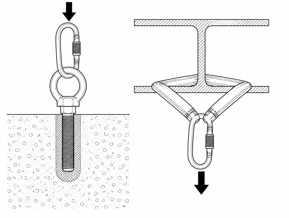
- Type B portable anchors — beam clamps, doorway posts, tripods — are only acceptable where the manufacturer declares a rated load covering the planned mass. Tripod head loads and leg-splay requirements are specific to each product; a tripod suitable for retrieving one person is frequently not suitable for 250 kg.
- Type C horizontal lifelines should not be used as a lowering anchor. A flexible line loaded at mid-span develops tension far above the applied load as its sag angle flattens, and the resulting end-anchor forces are difficult to predict on site.
- Type E deadweight anchors resist vertical arrest forces on a flat roof by mass and friction; they are not designed for sustained, horizontal-component pull from a load hanging over an edge.
The structure behind the anchor is a separate calculation, and it is the check most often skipped. Concrete pull-out capacity, edge distances for post-installed anchors, the local capacity of a beam flange or a purlin, and the direction of pull all need to be confirmed by a competent person — for the 5 kN class of forces described above, not for the load’s bare weight. Where documentation is missing, that verification belongs to a structural engineer before the lift, not to the crew on the day.
Sharing the load across two points — and the angle that undoes it
Two independent anchor points are standard practice for heavy loads, and the vector angle between the legs decides whether that helps.
| Included angle between legs | Force in each leg (as a multiple of the load) | Force in each leg at 250 kg |
|---|---|---|
| 0° (parallel) | 0.50 × | ≈ 1.2 kN |
| 60° | 0.58 × | ≈ 1.4 kN |
| 90° | 0.71 × | ≈ 1.7 kN |
| 120° | 1.00 × | ≈ 2.5 kN |
| 150° | 1.93 × | ≈ 4.7 kN |
At 120° each leg carries the entire load, and beyond that the arrangement amplifies rather than shares. Keeping the included angle at or below 90° is the practical working rule, with the master point positioned so the resultant pull points at the anchors rather than sideways off them.
Devices rated to lower 150 kg to 250 kg
This is where equipment selection is most often wrong, because the device that works fine every day for one person carries no permission for two.
- EN 12841 Type C descenders (rope access rope adjustment devices) are designed, tested and certified for a single user. Manufacturers state a maximum working load in the instructions, commonly around one person’s mass plus equipment. Some models are additionally certified to EN 341 with a higher declared rated load for rescue; unless that is stated in the instructions for use, a two-person load is outside the device’s approval.
- EN 341 descender devices for rescue are the usual answer for controlled lowering of person loads. The manufacturer must declare a minimum and maximum rated load and a descent energy figure. Rescue-rated descenders commonly declare a maximum rated load in the region of 200 kg, and some purpose-built units are higher — read the declared figure for the exact model in hand rather than assuming a class.
- EN 1496 rescue lifting devices can raise and, in the versions designed to do so, lower a person a limited distance. Rated load and permitted number of persons are product-specific.
- Hand-powered and powered lifting equipment for material loads: hand-powered lifting equipment to EN 13157, with a marked WLL comfortably above the load, plus rated slings and hooks with functioning latches.
Whatever the device, check three declared parameters together: rated load, compatible rope type and diameter range, and permitted descent height or descent energy. A descender fed with rope outside its stated diameter band loses braking predictability precisely when the load is heaviest.
Rope and connectors
Use low-stretch kernmantle rope to EN 1891 Type A, which has a higher minimum static strength than Type B and is intended for general use in rope access, rescue and work positioning; Type B is a lighter-duty product and is not the choice for heavy loads. Note that terminations reduce strength — a knotted termination is significantly weaker than the unknotted rope, which is why EN 1891 specifies separate figures for knotted samples.
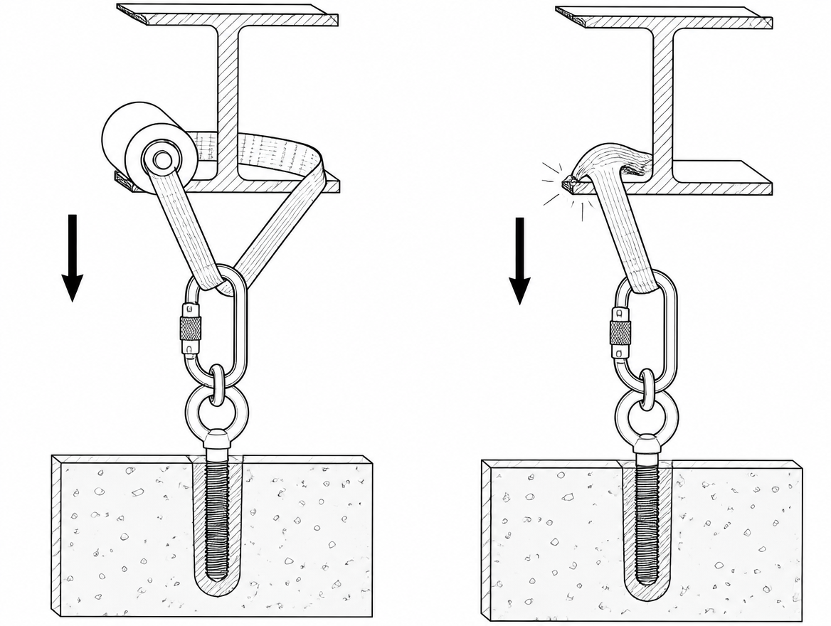
Connectors to EN 362 carry their major-axis strength marked on the body. That figure applies to the connector loaded along its spine with the gate closed and locked; loaded across the minor axis, or with the gate pressed against an edge, the available strength falls sharply. On a heavy load lowering anchor, use steel screwgate or triple-action connectors, keep them aligned along the intended axis, and eliminate any geometry that can rotate a connector against a beam edge or a bolt head as the load comes on.
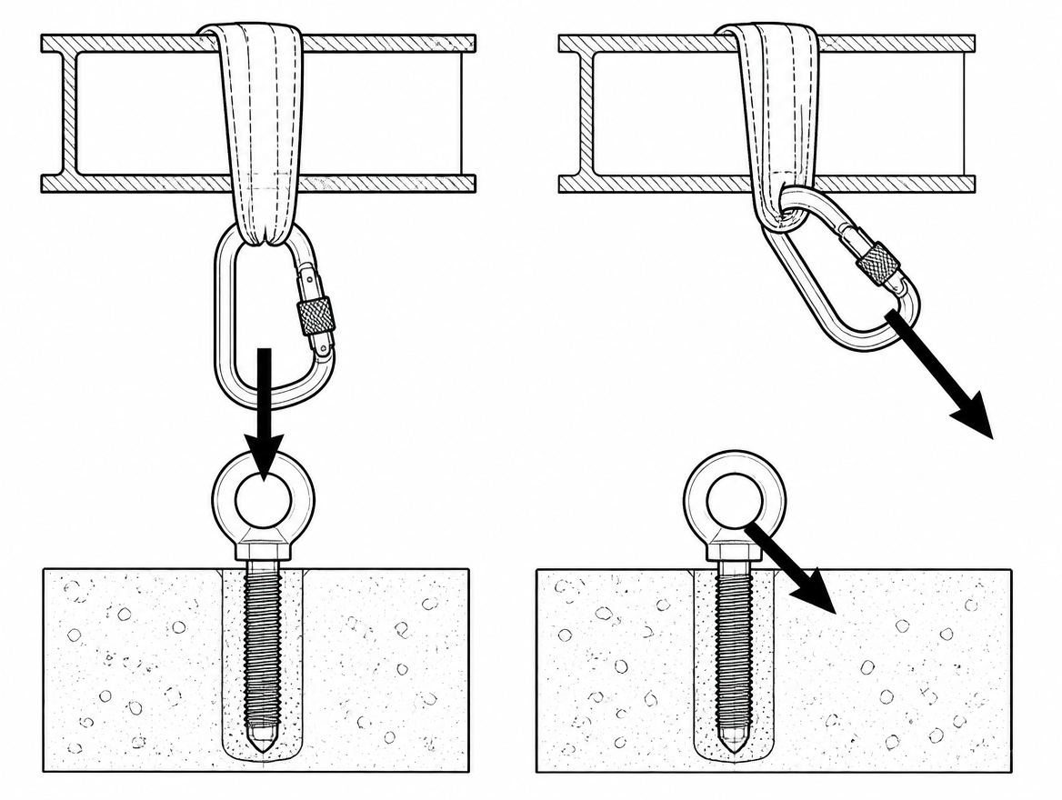
Pulleys and redirects
Every pulley in the system needs a declared rating for the force it will actually see — which, for a change of direction, is the vector sum of both rope legs, not the load. Pulleys certified to EN 12278 state a maximum working load and breaking strength; for material lifting operations, use lifting-rated sheaves with a marked WLL. Small-sheave pulleys also reduce rope efficiency and increase local bending; larger sheave-to-rope diameter ratios lower both losses and rope wear.
Rigging and running the lower
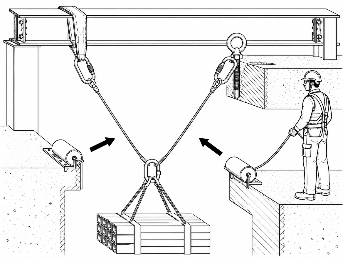
- Confirm the plan and the mass. Weigh or calculate the load, including rigging, tools and any attendant. Round up; do not estimate downwards.
- Build two independent systems. A main lowering line and a separate backup or belay line on an independent anchor point, each capable of holding the full load on its own. For person loads, verify that the backup device is rated for the total mass — many backup devices are one-person certified.
- Add friction ahead of time. With 250 kg on the rope, the operator should not be relying on grip strength. Use a device that offers variable friction (additional bars, extra wraps, a friction post) so the brake position is comfortably controllable and the tail line is manageable.
- Protect the rope at every edge. Rollers or edge protectors at the parapet, coping, or shaft lip, positioned so they stay in place as the load moves.
- Test the transfer before committing. Take the weight onto the system in a controlled way with the load still supported, check anchor components, connector alignment and device function, then release.
- Lower slowly and continuously. Smooth, moderate speed keeps forces static rather than dynamic. Avoid stop-start cycles that snatch the anchor.
- Keep communication one-directional and unambiguous. One person controls the lower, one person watches the edge and the load, and commands come from a single named role.
Heat is a real limit on long, heavy descents
Descent energy is mass × gravity × height. A 250 kg load lowered 25 m releases approximately 61 kJ (250 × 9.81 × 25 ≈ 61 300 J), nearly all of it dissipated as heat in the descender and the rope passing through it. EN 341 requires descender devices for rescue to be declared with a descent energy figure for exactly this reason. Practical consequences: metal parts can become hot enough to damage a rope sheath or a glove, aluminium components suffer more than steel on repeated heavy descents, and multiple back-to-back lowers compound the effect. On long shafts and tall façades, plan cooling pauses at points where the load can be safely held, and prefer steel-bodied devices for repeated heavy work.
Inspection, records and post-use decisions
EN 365 requires periodic examination of PPE against falls from a height by a competent person at intervals of at least every 12 months, or more frequently where the manufacturer’s instructions, the working environment or national legislation demand it. Heavy-load use accelerates that clock: pre-use checks before every lower, and a documented examination after any event outside normal use.
Remove from service and quarantine, pending examination by a competent person:
- any textile component that has taken a shock load or a load above its rated value;
- rope showing sheath glazing, hard spots, core deformation or abrasion from an unprotected edge;
- connectors with gate or locking-sleeve damage, or visible deformation from cross-loading;
- descenders with grooved, scored or heat-discoloured rope-bearing surfaces.
For lifting equipment and accessories used on material loads, keep the periodic inspection regime and thorough examination records required under the national implementation of Directive 2009/104/EC, with the WLL legible on every accessory.
Where this belongs in the management system
Heavy lowering is a planned operation, not an improvisation. Under ISO 45001:2018, clause 8.1.2 covers eliminating hazards and reducing risk — which for many of these tasks means asking whether the load has to be lowered on rope at all, or whether a crane, a hoist on a rated davit or a different removal route eliminates the suspended-load hazard. Clause 8.2 covers emergency preparedness and response, which is where two-person rescue lowering loads should be specified, rehearsed and equipped in advance, with the rated devices identified by model rather than by category.
The short version
For any lower in the 150 kg to 250 kg band, four figures decide whether the system is sound: the true mass of the load including rigging and attendant; the force at the anchor after redirects, angles and dynamic effects are added; the manufacturer’s declared rated load for every device in the chain; and the verified capacity of the structure the anchor is fixed to. If any one of the four is unknown, the operation is not yet planned.
Next step: pull the instructions for use for the specific descender, anchor device and backup device intended for the job, and compare their declared rated loads against the calculated anchor force — then review the anchor device certification against EN 795:2012 for single-person use or CEN/TS 16415 for simultaneous multi-person use, and record the result in the rescue or lifting plan for the task.
Frequently asked questions
Is a heavy lowering job a person load or a material load?
That is the first decision, and the regulatory route follows from it. A person load — rescue, suspended access, controlled descent of a casualty — falls under personal protective equipment to Regulation (EU) 2016/425, with harmonised standards such as EN 795 for anchor devices, EN 341 for descender devices for rescue, EN 1496 for rescue lifting devices, EN 1891 for low-stretch kernmantle rope and EN 362 for connectors. A material load — equipment, plant, spoil, a tool package — falls under lifting equipment and lifting accessories to Directive 2006/42/EC, with in-service inspection obligations from national implementations of Directive 2009/104/EC. Mixing the two is the most common source of confusion on site.
What happens when the load contains both a person and equipment, such as a stretcher with an attendant?
Where a load contains both, the person-load framework governs, and every component in the system must be rated for the combined mass declared by its manufacturer. A 250 kg motor lowered on PPE-rated rope through a PPE descender is not a compliant lifting operation, and a chain hoist rated 500 kg WLL is not automatically acceptable for lowering a person.
How much force does a 250 kg load actually put into the anchor point?
Static weight alone gives roughly 1.47 kN at 150 kg, 1.96 kN at 200 kg and 2.45 kN at 250 kg. But if the rope runs up to a pulley at the anchor and back down to a brake operator, the anchor becomes a redirect: both rope legs pull downwards, so the anchor carries roughly twice the load plus the friction component. A 250 kg load through a 180° redirect puts on the order of 5 kN into that single point before anything unexpected happens. Dynamic events — snatching the load off a ledge, an abrupt stop at the brake, a sling coming tight or a load shifting — can each double the force momentarily.
Which EN 795 anchor device types are suitable for heavy load lowering?
Type A structural anchors are usually the right starting point, provided the host structure has been verified. Type B portable anchors — beam clamps, doorway posts, tripods — are only acceptable where the manufacturer declares a rated load covering the planned mass; a tripod suitable for retrieving one person is frequently not suitable for 250 kg. Type C horizontal lifelines should not be used as a lowering anchor, because a flexible line loaded at mid-span develops tension far above the applied load as its sag angle flattens. Type E deadweight anchors resist vertical arrest forces by mass and friction and are not designed for sustained, horizontal-component pull from a load hanging over an edge. For a planned 200 kg two-person load, the device must be declared by its manufacturer for multi-person or heavy-load use, with CEN/TS 16415 covering anchor devices for more than one person at the same time.
Does sharing the load across two anchor points always reduce the force in each leg?
No — the included angle between the legs decides that. At 0° each leg carries 0.50 × the load (about 1.2 kN at 250 kg), at 60° 0.58 × (about 1.4 kN), at 90° 0.71 × (about 1.7 kN), at 120° 1.00 × (about 2.5 kN) and at 150° 1.93 × (about 4.7 kN). At 120° each leg carries the entire load, and beyond that the arrangement amplifies rather than shares. The practical working rule is to keep the included angle at or below 90°, with the master point positioned so the resultant pull points at the anchors rather than sideways off them.
Need this as a document you can issue? The template library gives you the risk assessments, permits and inspection logs in editable form — and employer plans cover a whole team with completion records.