Safety / Tips and Tricks / Rope access and confined space
Activity 01 · Rope access
Anchoring Two People to One Point: When a Shared Anchor Point Is Permitted
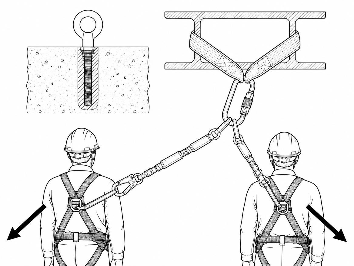
The question turns up on almost every roof, gantry and steelwork job: there is one anchor eye within reach, and two people who need to be attached. The decision is usually made in seconds, and it is usually made on the basis of how solid the anchor looks. That is the wrong basis. Whether a shared anchor point can carry two people at the same time is a documented property of that specific anchor device and the structure it is fixed to — stated by its manufacturer or installer, tested to a defined specification, and recorded on the system identification plate or in the instructions for use. It is not a judgement to be made by eye at the point of connection.
The default assumption in EN 795 is one person
EN 795:2012 is the European standard for anchor devices for personal fall protection equipment. It covers five types:
- Type A – anchor devices with one or more stationary anchor points, requiring structural anchors to fix them to the structure (for example an eyebolt into concrete or a plate bolted to steel).
- Type B – temporary portable anchor devices (beam clamps, anchor slings, door-frame and tripod-type devices).
- Type C – anchor devices employing a flexible horizontal anchor line, commonly called a horizontal lifeline.
- Type D – anchor devices employing a rigid horizontal anchor rail.
- Type E – deadweight anchor devices for use on horizontal surfaces within the slope limit given by the manufacturer.
The critical point for a shared anchor point is one of scope: EN 795:2012 is written around use by a single person. Testing under that standard establishes static strength — a sustained test load of 12 kN for metallic devices, and 18 kN where non-metallic components such as textile webbing form part of the load path — together with a dynamic performance test using a rigid test mass. Passing EN 795 therefore tells the reader that the device is fit for one user unless something else has been established in addition.
That “something else” is CEN/TS 16415, the technical specification covering anchor devices used by more than one person at the same time. It applies the EN 795 test regime with additional masses and increased test loads for each additional user, so a device declared to CEN/TS 16415 has actually been assessed for simultaneous multi-user loading. Where a device is only declared to EN 795:2012, a second person on the same point is outside the tested condition — not a marginal decision, but an untested one.
Two simultaneous arrests are not simply “twice a static load”
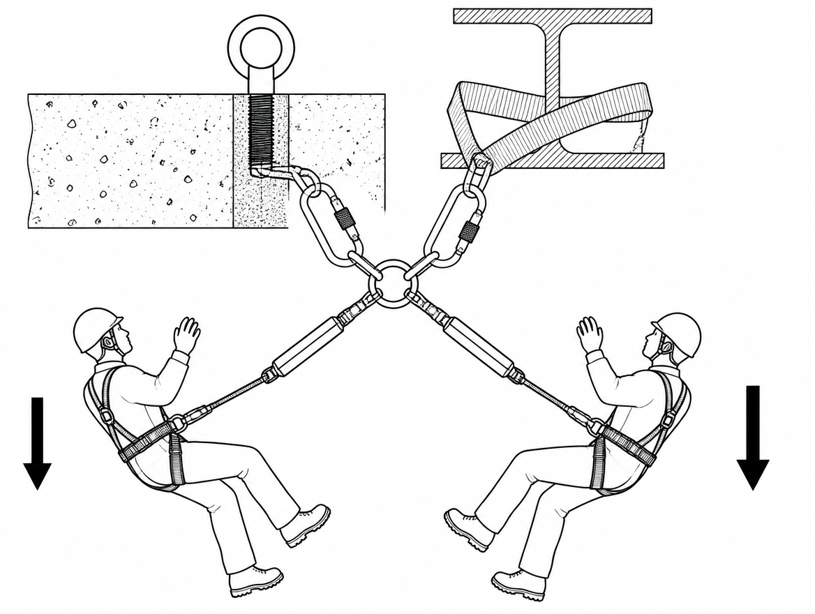
An EN 355 energy absorber limits the force transmitted to the user’s body during arrest; EN 361 full body harnesses distribute that force. Neither of those limits caps what the anchor sees when two arrests happen at once. Two people working from the same point are frequently exposed to the same trigger — a collapsing edge, a slipping platform, a swaying scaffold section — so treating the two falls as independent, unlikely-to-coincide events is not defensible in a risk assessment.
Beyond the arithmetic of adding two arrest forces, simultaneous loading changes behaviour:
- Loads arrive at slightly different times, so peak forces can occur while the device or the structure is already displaced.
- Off-axis pull becomes likely, because two falling people rarely load the point from the same direction.
- On flexible systems, the first fall changes the geometry the second fall is arrested in.
The device is only as good as the structural anchor behind it
A Type A device is not a complete anchor. EN 795 distinguishes the anchor device from the structural anchor — the element or elements that fix it to the structure — and the standard’s test values say nothing about the concrete, timber purlin, sandwich panel or corroded steel section on the other side of the fixing. Where two users are proposed on one point, the verification needs to cover the full load path: connector, anchor device, fixing, and base material.
In practice, that means a documented statement from the installer or a competent structural verification for the specific substrate and fixing, not a generic product datasheet. Permanently installed Type C and Type D systems are normally supplied with a fixed identification plate at the access point recording the permitted number of simultaneous users, the installer, and the date of installation or last examination. On those systems, the answer is already written down at the point of access, and reading it takes less time than debating it.
Connector geometry: two connectors crowded into one eye
Even where an anchor is rated for two people, the connection interface often is not. EN 362 connectors are strength-tested in a defined orientation — principally along the major axis with the gate closed and locked. Forcing two connectors into a single small anchor eye or a narrow eyebolt tends to produce exactly the loading conditions the test excludes: minor-axis (cross) loading, load applied against the gate or the locking sleeve, or one connector levered over the body of the other.
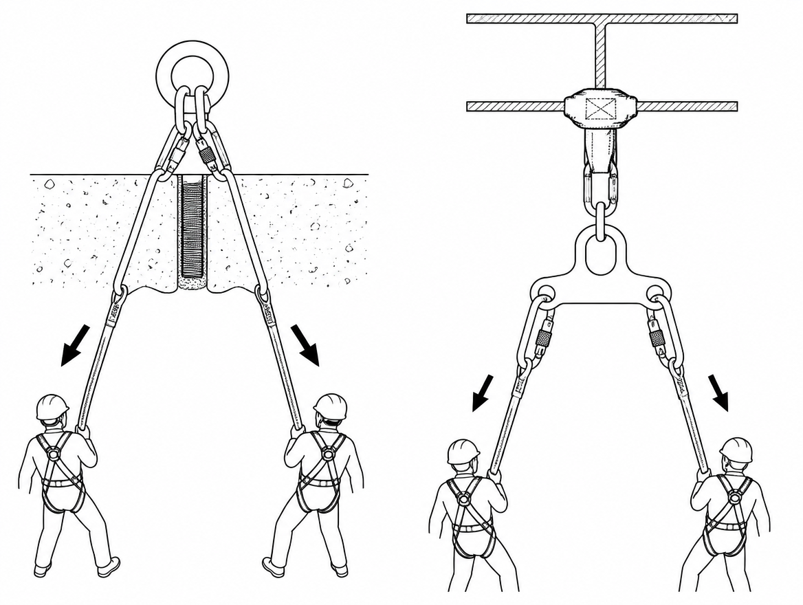
Where two attachments genuinely have to share one structural point, the correct hardware is an anchor plate or ring with separate, individually rated attachment holes, used within the manufacturer’s stated number of users. A shared eye is not a substitute for shared-rated hardware.
Type C lifelines: users per system and users per span
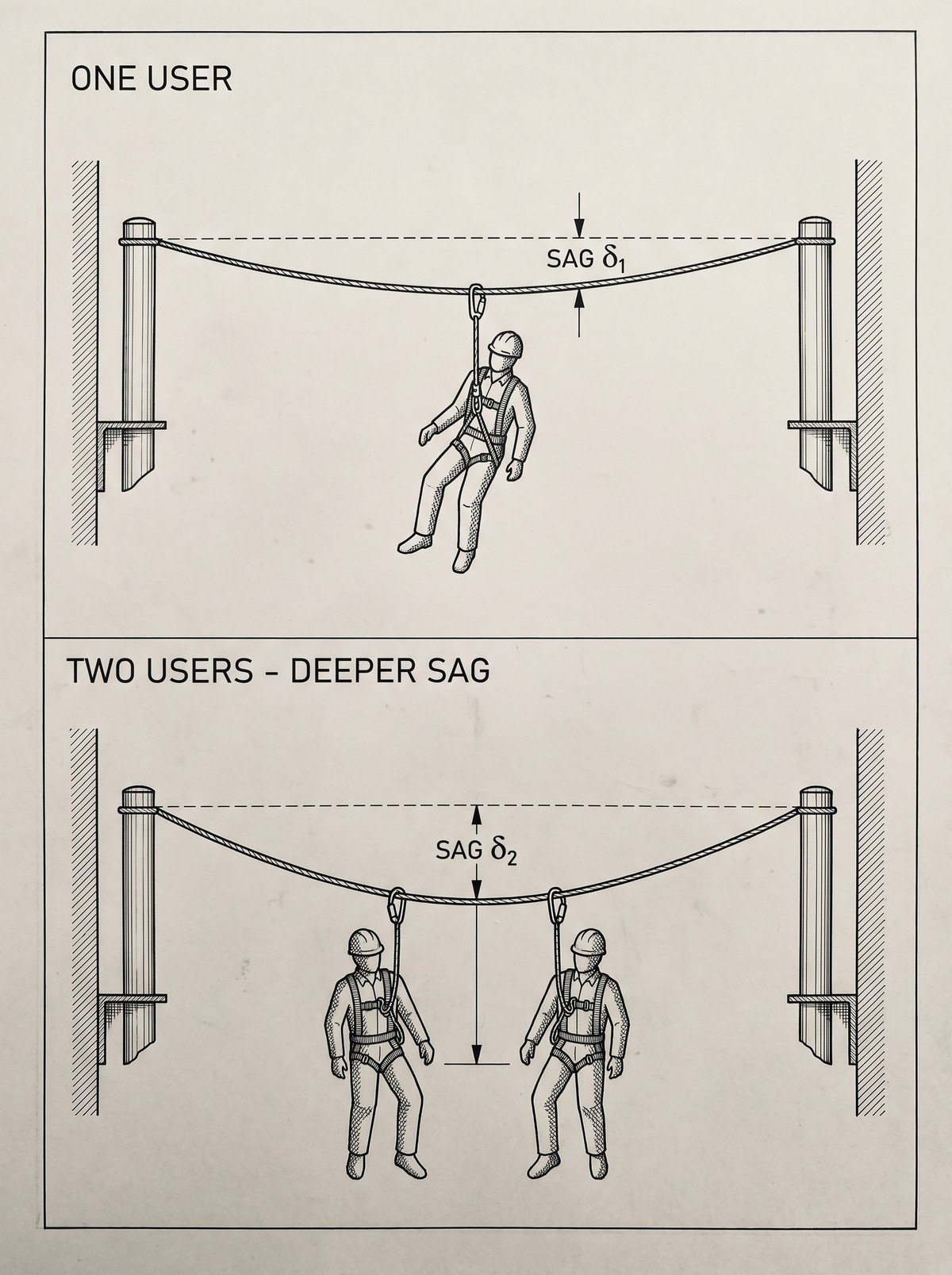
Horizontal flexible anchor lines are the most common place where “rated for more than one person” is misread. A Type C system declared for several users is normally limited to a smaller number of users per span between intermediate brackets, because line deflection — and therefore the fall distance — grows with span length and with the number of people loading that span at once.
Two consequences follow directly:
- Clearance changes. Required fall clearance below the working level is the sum of the connecting subsystem length, the deployment of the EN 355 energy absorber as stated by its manufacturer, the height of the user below the attachment point, and a safety margin — plus the deflection of the anchor line. Two users on one span increase the last term, and the manufacturer’s deflection table, not a rule of thumb, gives the figure to use.
- Guided type fall arresters are usually single-user devices. Equipment such as EN 353-2 guided type fall arresters on a flexible anchor line and EN 360 retractable type fall arresters is generally certified for one person per device and per line. Two people on one vertical line, or two lanyards clipped to one retractable device’s connector, are outside that certification.
Interference, pendulum and collision between the two users
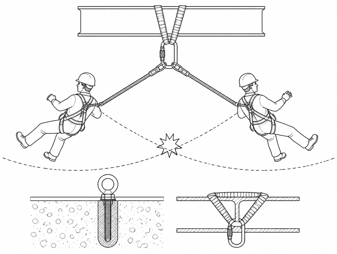
Strength is not the only failure mode of a shared anchor point. Two people attached to one point work on converging radii. If both move toward different edges, both introduce swing potential, and their swing arcs can intersect. A single arrest can then pull the second person off balance, drag a slack lanyard across a sharp edge, or put two bodies on a collision path during the swing.
Two independent anchor points, spaced so that each user’s working sector and swing arc are separated, remove this problem entirely and are frequently easier to justify than a multi-user rating for a single point. Where separation is impossible, the work sequence has to keep the two users on the same side of the anchor and out of each other’s swing path.
The load that gets left out of the calculation: rescue
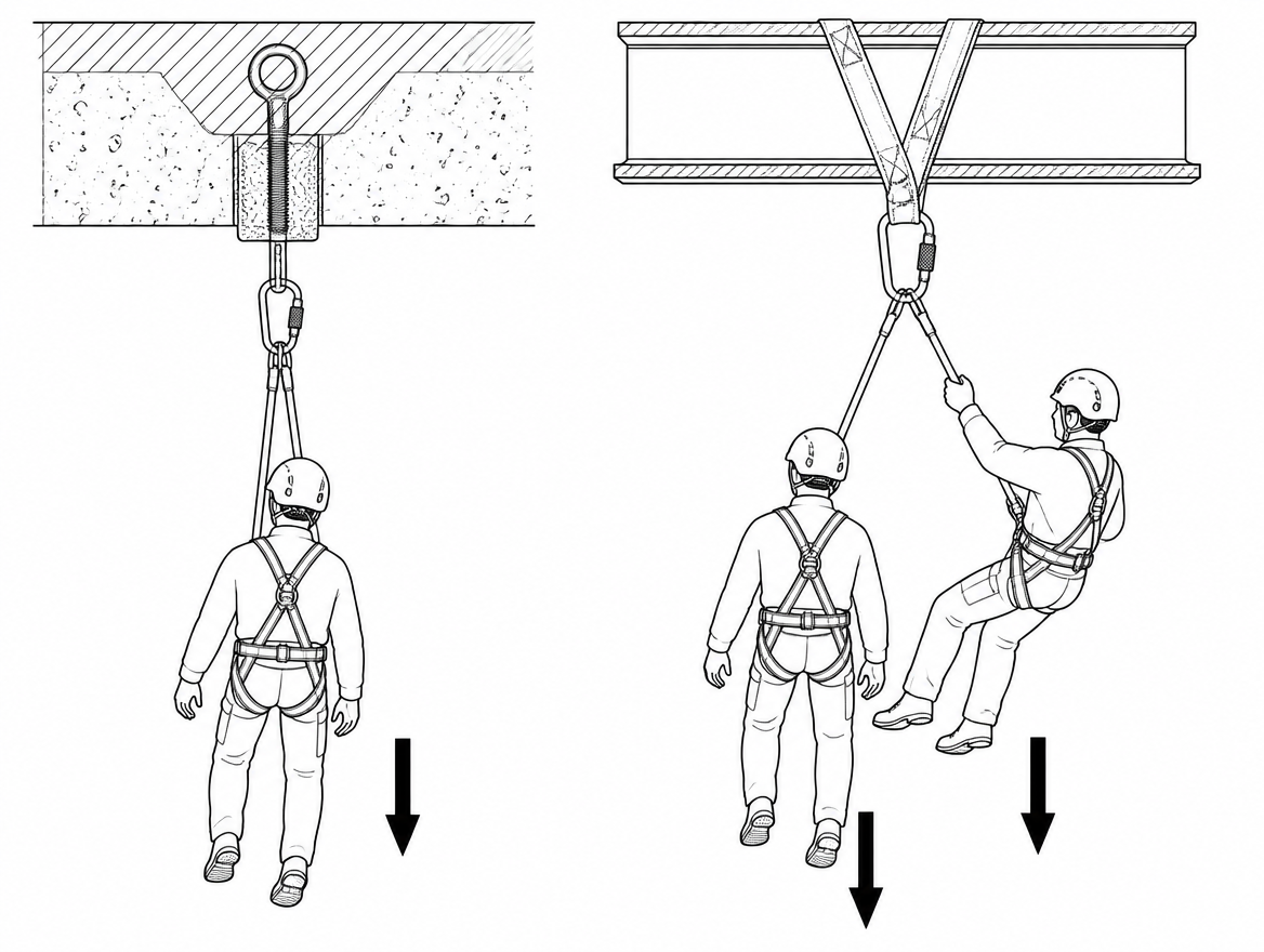
A fall arrest system that has done its job leaves a person suspended. Rescue from suspension normally applies a further load to an anchor — a rescue lifting device to EN 1496, a descender or lowering device, or the mass of a second person on a rescue line. If the rescue plan uses the same point that arrested the fall, the anchor has to be rated for that combined condition as well.
This is where a nominally adequate shared point often fails on paper: rated for two users in fall arrest, but with no capacity declared for a rescue load applied on top of a suspended casualty. Identifying a separate, verified rescue anchor before work starts avoids improvising one under time pressure with a colleague hanging in a harness.
Work restraint and work positioning: lower loads, same question
Work restraint keeps the user away from the fall edge, so no arrest force arises and the loads on the anchor are low. Work positioning to EN 358 sits between the two, with a belt or positioning lanyard loaded in normal use and a separate fall arrest system as backup. Lower loads do not remove the need for a rating: an anchor device declared for one person in fall arrest may or may not be authorised by its manufacturer for two people in restraint, and the instructions for use are the only source for that. Restraint also depends on lanyard length discipline — two people sharing a point with adjustable lanyards can easily leave one of them within reach of an edge.
Rope access: independence, not sharing
Rope access practice runs in the opposite direction to anchor sharing. Each user works on a working line and a separate safety line, with rope adjustment devices to EN 12841, and the two lines are intended to be independently anchored so that a single anchor failure cannot take out both. A two-person team therefore needs an anchor arrangement that keeps four lines independent — not a single point serving as the common origin for all of them.
A decision sequence for the point of use
- Read the identification plate or the instructions for use. EN 365 requires anchor devices to be supplied with instructions for use; the permitted number of simultaneous users is stated there, and on permanent Type C and Type D systems it is normally on the plate at the access point.
- Check the declaration. EN 795:2012 alone indicates single-person assessment; CEN/TS 16415 indicates that multi-user simultaneous loading has been assessed.
- Check the span, not just the system. On a horizontal line or rail, apply the per-span user limit and take the deflection figure from the manufacturer’s data.
- Recalculate clearance for the actual number of users on the span, using the stated energy absorber deployment for the specific product in use.
- Check the interface. One rated attachment hole per connector; no stacked connectors in a single eye; connectors loaded along the major axis with gates closed and locked.
- Check the structural anchor and substrate for the increased load, with installer or structural verification where the base material is not covered by a documented fixing specification.
- Confirm the rescue anchor separately, including any EN 1496 device or lowering arrangement.
- If any step cannot be answered from documentation, use two anchor points. An untested shared point is not made acceptable by the absence of a better option.
What to record
Where a shared anchor point is used deliberately, the decision belongs in the written risk assessment and the method statement, together with the anchor identification, its declared number of users, the clearance calculation used, and the rescue arrangement. Under an ISO 45001 management system, a change in the number of users on an existing anchor is a change to a control measure and is handled through the organisation’s change-management and hazard-identification process rather than informally on site.
Anchor devices and the connecting subsystems attached to them are subject to periodic examination by a competent person under EN 365, at intervals no longer than 12 months unless the manufacturer’s instructions or national legislation require a shorter interval. Multi-user anchors deserve particular attention at examination: they carry higher loads, they are usually fixed installations exposed to weather, and their identification plates are the only on-site record of how many people may use them.
Takeaway
Treat the number of users as a marked, documented property of the anchor — the same way as its type and its examination date. If the plate or the instructions do not state that the point may serve two people simultaneously, and if a CEN/TS 16415 declaration is not available, the second person gets their own anchor. For verification of a specific installation, the documents to request are the manufacturer’s instructions for use, the installer’s fixing and substrate specification for the structural anchor, and the most recent periodic examination record.
Frequently asked questions
Can two people be attached to the same anchor point?
Only where that specific anchor device and the structure it is fixed to have been documented as suitable for simultaneous multi-user loading — stated by the manufacturer or installer, tested to a defined specification, and recorded on the system identification plate or in the instructions for use. It is not a decision to be made by eye at the point of connection on the basis of how solid the anchor looks.
What does EN 795:2012 assume about the number of users?
EN 795:2012 is written around use by a single person. Its testing establishes static strength — a sustained test load of 12 kN for metallic devices and 18 kN where non-metallic components such as textile webbing form part of the load path — plus a dynamic performance test using a rigid test mass. Passing EN 795 therefore tells you the device is fit for one user unless something else has been established in addition.
What is CEN/TS 16415 and why does it matter?
CEN/TS 16415 is the technical specification covering anchor devices used by more than one person at the same time. It applies the EN 795 test regime with additional masses and increased test loads for each additional user, so a device declared to CEN/TS 16415 has actually been assessed for simultaneous multi-user loading. Where a device is declared only to EN 795:2012, a second person on the same point is outside the tested condition — an untested one, not a marginal decision.
Why are two simultaneous fall arrests not just twice a static load?
Beyond adding two arrest forces, simultaneous loading changes behaviour: loads arrive at slightly different times, so peak forces can occur while the device or structure is already displaced; off-axis pull becomes likely because two falling people rarely load the point from the same direction; and on flexible systems the first fall changes the geometry in which the second fall is arrested. An EN 355 energy absorber limits the force transmitted to the user's body and an EN 361 harness distributes it, but neither caps what the anchor sees when two arrests happen at once. Two people working from the same point are also frequently exposed to the same trigger, so treating the falls as independent, unlikely-to-coincide events is not defensible in a risk assessment.
Is it acceptable to clip two connectors into one anchor eye?
No. Forcing two connectors into a single small anchor eye or a narrow eyebolt tends to produce exactly the conditions EN 362 testing excludes: minor-axis (cross) loading, load applied against the gate or locking sleeve, or one connector levered over the body of the other. Where two attachments genuinely have to share one structural point, the correct hardware is an anchor plate or ring with separate, individually rated attachment holes, used within the manufacturer's stated number of users. A shared eye is not a substitute for shared-rated hardware.
Need this as a document you can issue? The template library gives you the risk assessments, permits and inspection logs in editable form — and employer plans cover a whole team with completion records.