Safety / Tips and Tricks / Rope access and confined space
Activity 01 · Rope access
Descending with Additional Braking: When a Descender Needs Extra Friction and How to Add It
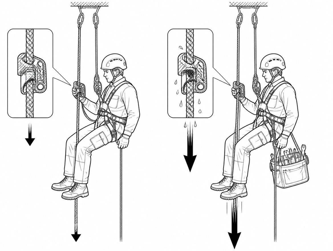
A descender that feels perfectly controlled on a dry 11 mm rope with a 75 kg operator can run noticeably faster on a wet 10 mm rope with a 110 kg operator carrying a tool bag. The device has not changed and it has not failed — the friction available to it has dropped. Additional braking is the routine, manufacturer-sanctioned way of putting that friction back, and knowing when to add it is part of basic competence for anyone working on rope.
This article covers what additional braking does, the conditions that make it necessary, the standards framework that applies in Europe, and how to rig and test the extra friction without introducing a new problem.
What “additional braking” means on a descender
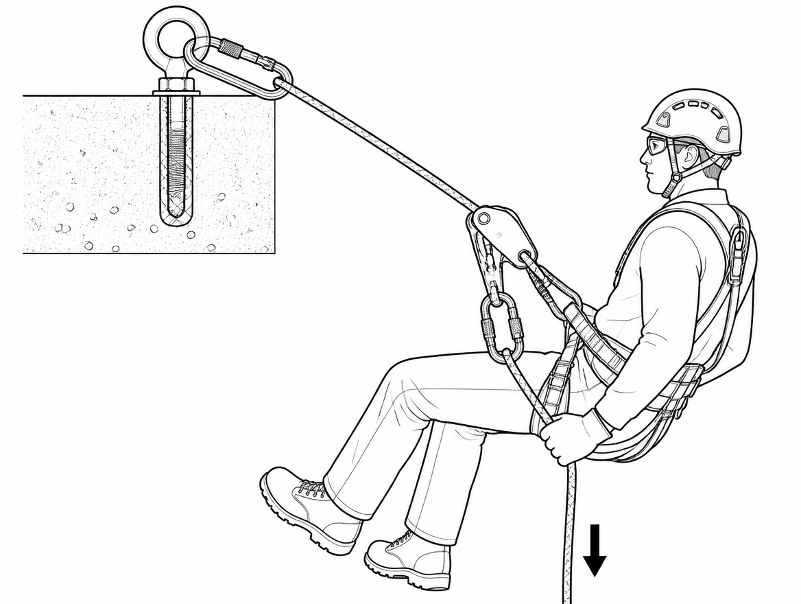
A self-braking descender controls speed by forcing the rope through a tortuous path — around a cam, over a fixed sheave, across a friction surface — while the operator’s brake hand holds the tail of the rope. The braking force the device can generate depends heavily on how much tension the operator maintains on that tail. Additional braking increases the friction acting on the tail rope, typically by routing it through a locking connector fitted to the point on the device body provided for that purpose, so a given hand force produces more retardation.
Two points follow from that description and both matter:
- Additional braking supplements the brake hand. It does not replace it. Every descender covered by EN 12841:2024 Type C or EN 341:2011 is designed and certified on the assumption that the tail rope is controlled.
- Additional braking is not a backup. In a two-rope rope access system, the backup device on the safety line — a Type A device under EN 12841:2024 — remains a separate, mandatory element.
The variables that change how much friction you actually get
Descender friction is not a fixed property of the device. The main variables encountered on site are:
- Rope diameter. Devices are certified over a stated diameter range and often permitted over a wider working range. A rope at the thin end of the range passes through the device with markedly less friction than one at the thick end.
- Sheath condition. A new rope with a tightly woven, unabraded sheath is slick. A used, slightly fuzzed rope grips better. Ropes contaminated with mud, silt or release agent behave like lubricated ropes.
- Water and ice. Wet polyamide rope is the single most common cause of an unexpectedly fast descent. Frozen or ice-glazed rope is worse and also stiffens, changing how the cam bites.
- Total suspended mass. Operator plus harness, plus tools, plus a hauled load. Doubling the mass does not double the braking capacity of a hand on the tail rope.
- Rope construction and stiffness. Low-stretch kernmantel ropes to EN 1891:1998 Type A vary between manufacturers in sheath weave and handling; a stiff rope can hold the cam open slightly, a very supple one can feed faster.
- Descent length. On a long descent the weight of rope hanging below the device adds tail tension at the start and removes it near the bottom, so the same device gets progressively harder to control as the descent proceeds.
When to add braking
Add additional braking before leaving the anchor whenever one or more of the following applies:
- The suspended load is heavier than the operator alone — rescue loads, two-person descents, casualty evacuation, or an operator carrying substantial tooling.
- The rope is wet, iced, muddy or contaminated.
- The rope is new, or the sheath is smooth and unworn.
- The rope diameter sits at the lower end of the device’s certified range.
- The descent is long, free-hanging, or ends over water or an obstruction where a controlled stop is critical.
- The operator’s grip is compromised — thick winter gloves, cold hands, an injury, or fatigue late in a shift.
- The manufacturer’s instructions require it for the intended application, which is common for rescue-rated use.
If more than one factor is present — a rescue load on a wet rope, for example — treat the effect as cumulative, not as a single reason to add a single carabiner.
Where the standards sit
Additional braking is a technique rather than a certified product, but the equipment it is applied to is governed by a clear framework:
- EN 12841:2024 — Rope access systems — Rope adjustment devices. Type C covers descenders on the working line; Type A covers backup devices on the safety line; Type B covers ascenders. Type C certification is based on a maximum rated load declared by the manufacturer, which for most devices reflects single-person use.
- EN 341:2011 — Descender devices for rescue. Devices are placed in classes according to the descent energy and duty they are tested for, with Class A the most demanding. Where a descender is intended for two-person rescue loads, the manufacturer’s EN 341 rating and the accompanying instructions are the documents that define the permitted load and rope.
- EN 1891:1998 — low-stretch kernmantel ropes. Type A is the normal choice for rope access working and safety lines.
- EN 362:2004 — connectors. Any carabiner used to add braking must be a locking connector, not a snap gate or an accessory karabiner.
- EN 813:2024 and EN 361:2002 — the sit harness ventral attachment used for suspension and the full-body harness fall arrest attachments respectively.
- EN 365:2004 — general requirements for instructions for use, maintenance and periodic examination, including examination by a competent person at intervals appropriate to use and at least annually for most equipment.
Critically, the permitted method of adding braking is defined by the device manufacturer’s instructions for use, not by the standards themselves. Descenders differ: some provide a dedicated hole in the side plate for a braking carabiner, others specify routing the tail through a connector on the harness attachment point, others (racks, bar-type descenders) add friction by engaging further bars. Applying one device’s method to another is where most rigging errors originate.
Rigging a braking carabiner: the sequence
- Confirm the method in the instructions for use. Identify the attachment point the manufacturer designates for additional braking and the rope path through it.
- Rig the descender on the working line first and check the rope is installed in the correct direction — anchor side and brake side as shown in the device’s own diagram moulded or printed on the body.
- Install the backup device on the safety line and connect it to the harness before adding friction hardware, so the system is protected while you finish rigging.
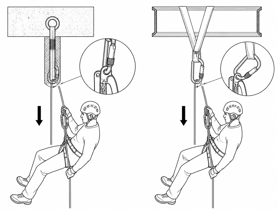
- Clip the locking connector into the designated braking point, gate orientation such that the loaded rope cannot press on the gate or unscrew the sleeve.
- Route the tail rope through the connector as specified, then close and lock the gate. Verify the lock by sight and by touch.
- Check for interference. The connector must not foul the handle, the cam, the anti-panic mechanism, or the descender’s attachment connector, and the rope must not run across the harness webbing, a gear loop, or a lanyard.
- Perform a loaded function test before committing (see below).
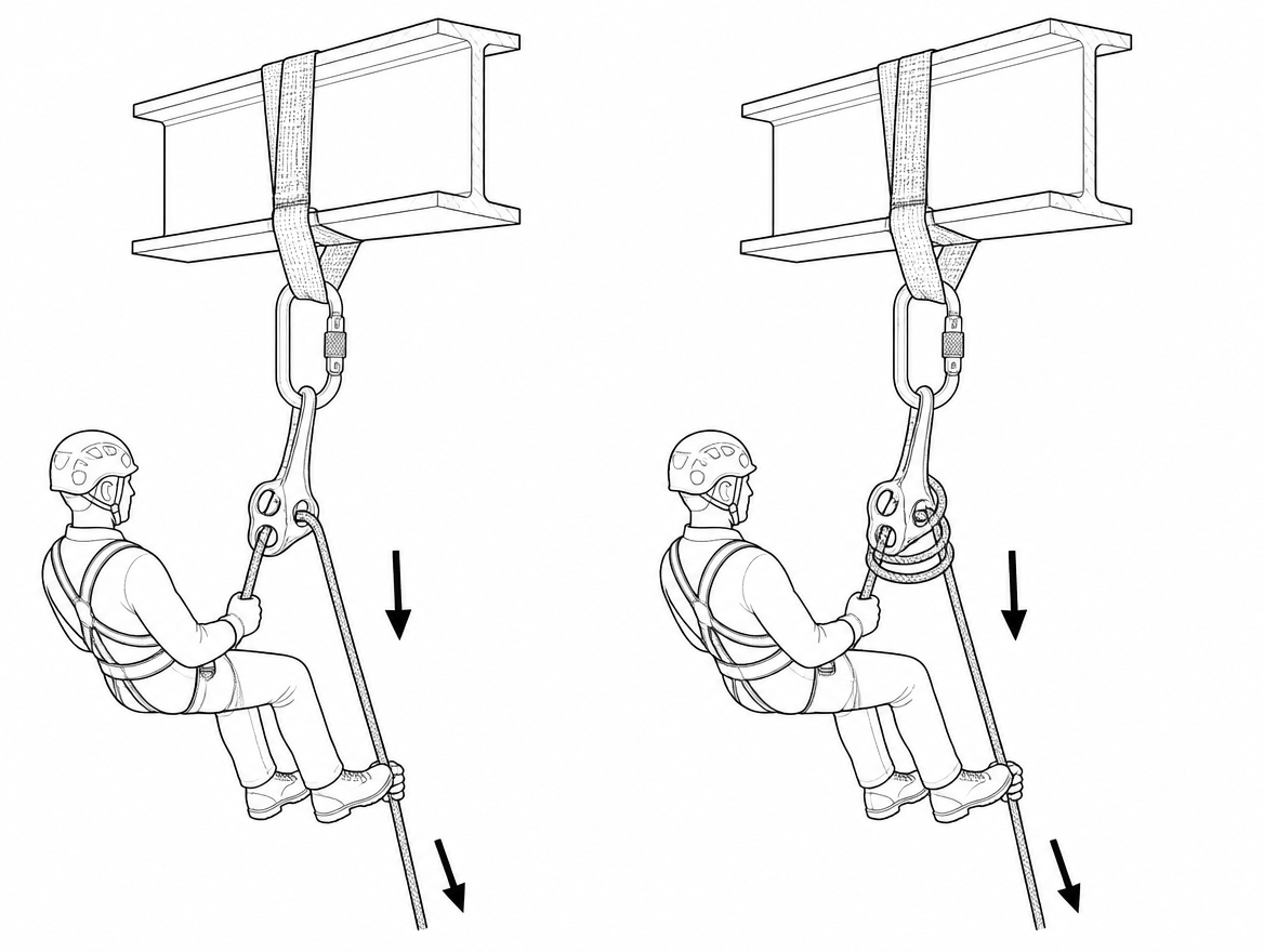
The loaded function test
Adding friction changes the feel of the device, sometimes substantially. A handle position that gave a comfortable 0.3 m/s before will give almost nothing afterwards, and an operator who compensates by opening the handle further can find themselves in the device’s unlocking or anti-panic range without meaning to be.
Test while you can still step back onto the structure:
- Transfer weight fully onto the working line with the brake hand on the tail.
- Open the control gradually and descend 200–300 mm.
- Stop, release the handle, and confirm the device holds without hand tension.
- Repeat with the tool bag or load attached, since load position changes the tail angle.
- Confirm the backup device runs freely on the safety line and locks when tested.
If the device now feels so stiff that progress requires wrestling the handle, that is a signal to remove one element of friction rather than to fight it — an over-braked system encourages the operator to hold the handle open continuously, which defeats the self-braking function.
Common rigging errors
- Clipping the braking carabiner to a gear loop or equipment ring. Gear loops are not rated for functional loads. The braking connector belongs on the point the manufacturer designates on the device or harness attachment.
- Cross-loading. A round-stock carabiner that rotates under a tail rope can end up loaded across the minor axis or with the rope bearing on the gate. Choose a connector shape and orientation that stays put, or a captive-eye connector where the manufacturer permits one.
- Rope running over the harness or over another rope. Rope-on-rope contact under load produces rapid sheath damage and, at descent speed, heat sufficient to melt polyamide.
- Braking connector fouling the handle. If the extra hardware can jam the control lever, the operator loses the ability to modulate speed at exactly the point they need it.
- Treating additional braking as a substitute for the backup device or for a rescue plan.
- Adding braking on the safety line. Additional friction belongs on the working line descender. A Type A backup device must be free to travel and lock as designed.
Heat, speed and rope damage
Friction converts potential energy into heat, and that heat goes into the device body and the rope sheath. Manufacturers of self-braking descenders commonly specify a maximum descent speed of 2 m/s; the limit exists because both the aluminium body and the rope have a thermal ceiling. Polyamide, the usual sheath material, begins to soften and then melt in the region of 215–220 °C, and a glazed, hardened patch on a sheath after a fast descent is evidence that the limit was approached.
Additional braking helps here in two ways: it reduces the tendency to descend fast in the first place, and it distributes friction across more than one contact point. It does not license faster descents. After any long or heavy-load descent, run the working line through gloved hands and inspect for glazing, sheath flattening, or a warm device body before the next descent, and record anything found in the equipment inspection log required under EN 365:2004.
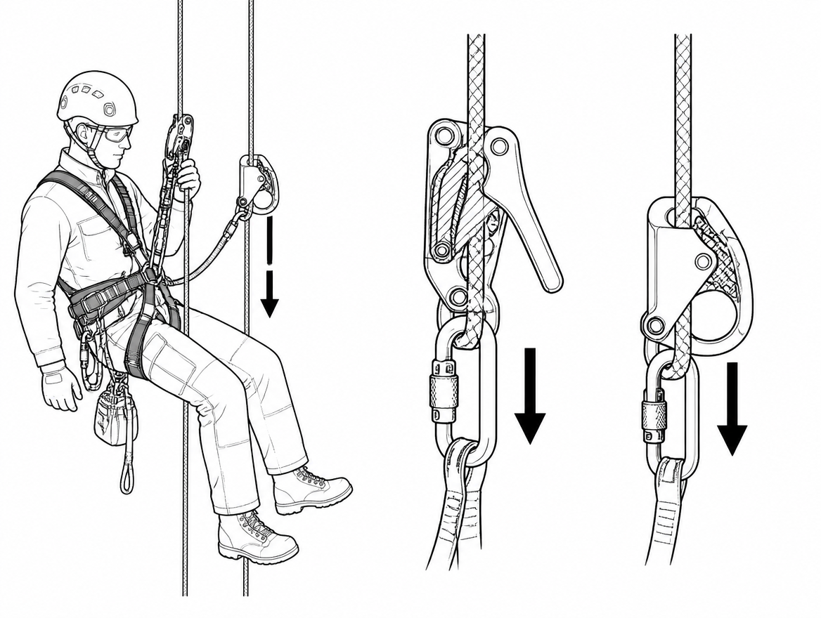
Adding or removing braking part-way down
Occasionally a descent starts on a wet, heavily loaded rope and finishes with most of the rope weight gone from below the device, or a descent that began in the shade of a structure continues down a slick, contaminated section. Some devices permit the braking connector to be added or removed mid-descent; many do not, and doing so always means working one-handed on a live system.
Where a change of friction is likely to be needed, the safer sequence is:
- Stop and lock the descender in its parked position.
- Take the load onto a work positioning lanyard or a secondary attachment where an anchor or structure allows.
- Verify the backup device is engaged on the safety line.
- Make the change with the tail rope still held or secured with a stopper knot below the device.
A stopper knot in the tail of the working line is worth mentioning in its own right. On any descent where the rope may not reach the intended landing — and particularly on rescue descents where the length is estimated — a knot in the free end removes the worst outcome of a device running out of rope.
Rescue loads deserve their own rehearsal
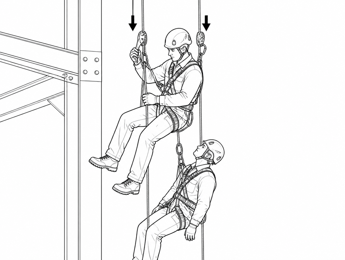
Two-person loads are where additional braking moves from useful to necessary, and where the difference between a rated descent and an improvised one becomes obvious. Before relying on a descender for a rescue load, confirm three things in the manufacturer’s documentation: that the device carries a rescue rating under EN 341:2011 for the load in question, that additional braking is specified for that use, and that the rope diameter and type in your kit are among those the rescue rating was established with.
Rehearse it with a mass equivalent to the intended rescue load, not with a single operator. The handle response, the hand force required and the rate at which heat builds all change with load, and a rescue is the wrong moment to discover it.
Practical takeaway
Treat additional braking as a default response to a specific, identifiable set of conditions — heavier loads, wet or new rope, thin rope, long or free-hanging descents, compromised grip — rather than as an advanced technique reserved for unusual jobs. Rig it only by the method the device manufacturer specifies, always with a locking connector to EN 362:2004, always with a loaded function test before committing to the rope, and never in place of the Type A backup device on the safety line.
The next step for most teams is documentary rather than technical: check that the rope access method statement and the rescue plan name the conditions that trigger additional braking, so the decision is not left to individual judgement on a wet morning. Pair that with the device’s instructions for use in the equipment file and the periodic examination record required under EN 365:2004.
Frequently asked questions
What does additional braking actually do on a descender?
It increases the friction acting on the tail rope, typically by routing the tail through a locking connector fitted to the point on the device body provided for that purpose, so that a given hand force produces more retardation.
Does additional braking replace the brake hand or the backup device?
No. Additional braking supplements the brake hand and does not replace it — every descender covered by EN 12841:2024 Type C or EN 341:2011 is designed and certified on the assumption that the tail rope is controlled. It is also not a backup: in a two-rope rope access system the backup device on the safety line (a Type A device under EN 12841:2024) remains a separate, mandatory element.
Which conditions call for adding braking before leaving the anchor?
Add it when the suspended load is heavier than the operator alone (rescue loads, two-person descents, casualty evacuation, or substantial tooling); when the rope is wet, iced, muddy or contaminated; when the rope is new or the sheath is smooth and unworn; when the rope diameter sits at the lower end of the device's certified range; when the descent is long, free-hanging, or ends over water or an obstruction where a controlled stop is critical; when the operator's grip is compromised by thick winter gloves, cold hands, injury or fatigue; and when the manufacturer's instructions require it for the intended application.
Why can the same descender feel faster on a different job?
The friction available to the device changes. Rope diameter, sheath condition, water and ice, total suspended mass, rope construction and stiffness, and descent length all affect friction. For example, wet polyamide rope is the single most common cause of an unexpectedly fast descent, and on a long descent the weight of rope hanging below the device adds tail tension at the start and removes it near the bottom, so control becomes progressively harder as the descent proceeds.
Which standards apply, and where is the permitted braking method defined?
EN 12841:2024 covers rope adjustment devices (Type C descenders, Type A backups, Type B ascenders); EN 341:2011 covers descender devices for rescue, with classes based on descent energy and duty and Class A the most demanding; EN 1891:1998 Type A covers low-stretch kernmantel ropes; EN 362:2004 covers connectors, and any carabiner used to add braking must be a locking connector, not a snap gate or accessory karabiner; EN 813:2024 and EN 361:2002 cover harness attachments; and EN 365:2004 covers instructions, maintenance and periodic examination. Critically, the permitted method of adding braking is defined by the device manufacturer's instructions for use, not by the standards themselves.
Need this as a document you can issue? The template library gives you the risk assessments, permits and inspection logs in editable form — and employer plans cover a whole team with completion records.