Safety / Tips and Tricks / Rope access and confined space
Activity 01 · Rope access
Choosing Connectors for Hauling and Pulleys
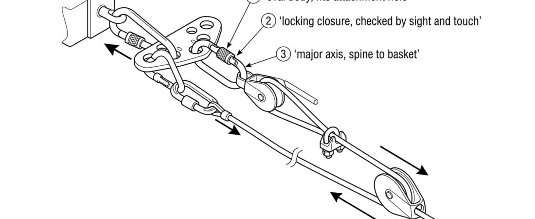
In a hauling system, the connector between the pulley and the anchor is one of the most heavily loaded components on the site. Mechanical advantage multiplies the force the haul team applies, redirects add vector loads on top of that, and every one of those forces passes through a single piece of hardware whose shape decides whether the pulley stays aligned or works its way onto the gate. Choosing connectors for hauling and pulleys is therefore less about breaking strength than about geometry: the right cross-section for the attachment hole, the right shape to keep the pulley centred, and the right closure for how often the connection will be opened.
This note covers the practical selection criteria for connectors used with pulleys in rope-access and confined-space hauling systems, and the loading errors that most often show up on inspection.
Why oval bodies dominate pulley attachments
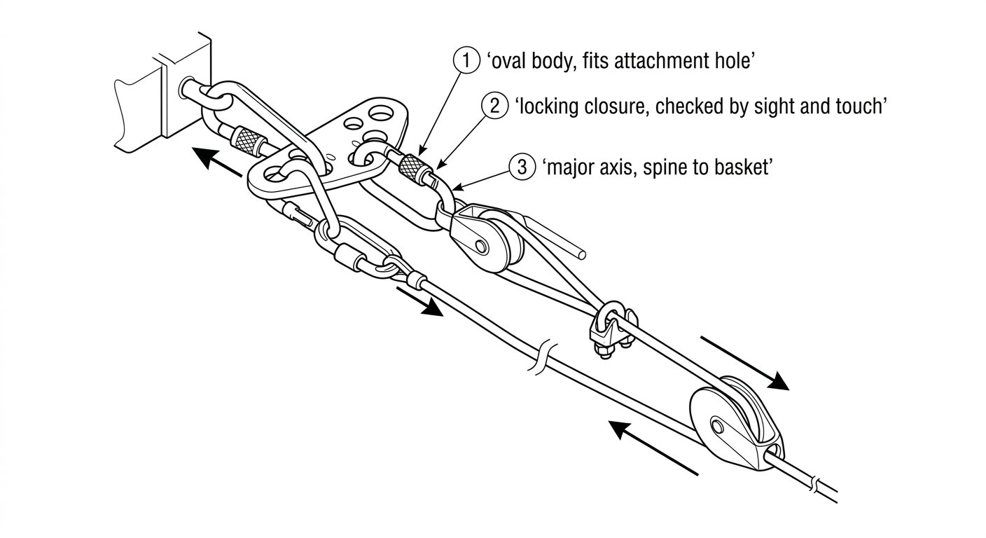
A pulley hangs from a connector by an attachment hole in its cheek plates or swing side. The connector’s cross-section sits inside that hole, and the pulley then rotates and settles wherever the geometry allows. A symmetrical oval keeps the pulley on the centre line of the connector, so the load runs down the major axis (spine to basket) with minimal tendency to shift.
Asymmetric shapes behave differently. An offset-D concentrates load toward the spine, which is efficient for a single sling or lanyard end but pushes the pulley toward the narrow end of the connector, where the attachment hole may ride up against the nose or gate. A wide pear-shaped (HMS) body gives a large basket that lets the pulley slide and rotate as the direction of pull changes during a haul. Neither is inherently unsafe, but neither holds the pulley where you put it. For a general overview of how body shape drives placement decisions, see the note on connector shapes and where each belongs.
Two shape-related checks are worth making before the system is built:
- Cross-section thickness versus hole size. Large-diameter or heavily profiled connector bodies will not always pass through the attachment hole of a compact pulley, or will pass through but bind so tightly that the pulley cannot align itself with the load. Test the pairing physically rather than assuming.
- Clearance to the sheave. The connector must not contact the rotating sheave or trap the rope between connector body and cheek plate. On some small pulleys, an oversized connector will foul the rope path.
Keep the connector loaded on its major axis
Connectors intended for personal fall protection are certified under EN 362, the standard for connectors in fall protection systems, and their rated strength is a major-axis figure with the gate closed and locked. Strength drops substantially when the connector is loaded across the minor axis, over the gate, or in three directions at once. Hauling produces all three failure modes readily, because the direction of pull changes as the load moves and because riggers tend to add items to whatever connector is already in place.
Common loading errors at the pulley:
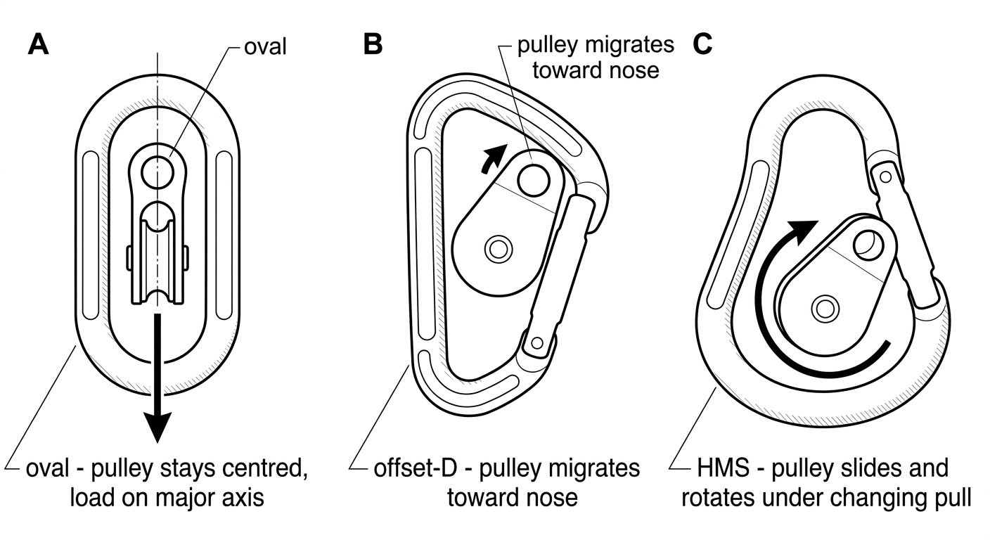
- Cross-loading. The pulley presses on one side of the connector while the anchor sling pulls from the other, levering the connector across its minor axis. Usually caused by a sling or anchor plate that cannot rotate freely.
- Gate loading. The pulley cheek migrates onto the gate, especially with asymmetric bodies or when the connector is too large for the hole. Any load path that bears on the gate rather than the spine is unacceptable.
- Three-way loading. A pulley, a rope clamp and a sling all sharing one connector. As the haul progresses, one of those three items ends up pulling at an angle the connector was never rated for.
The fix for three-way loading is nearly always to reduce the number of items in the connector rather than to add strength. A double pulley with a becket, a dedicated progress-capture pulley, or a rigging plate that gives each item its own hole will keep every connector in the system loaded end to end. The same principle governs the hardware at the top of the system, discussed in the note on choosing connectors for anchor rigging.
Closure: screw-lock, two-stage or three-stage
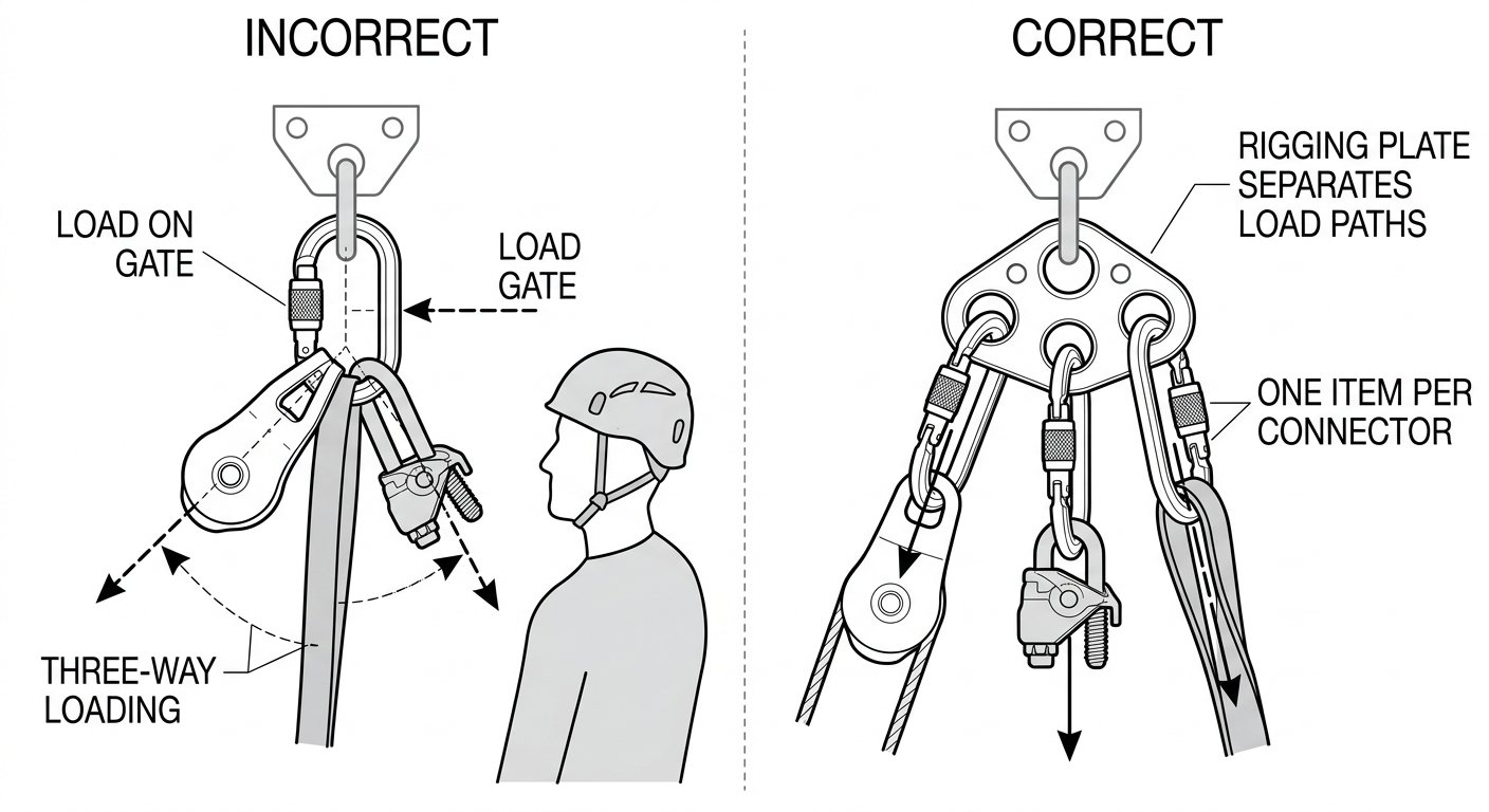
Locking is mandatory for hauling connectors; non-locking connectors have no place in a load path. The choice between closure types follows how the connection is used:
- Screw-lock (manual). Suited to connections built once at the start of the job and left closed: the anchor-side connector on a haul pulley, a becket connection, a directional. Fewer moving parts, tolerant of dirt, but requires a deliberate visual and tactile check that the sleeve is fully closed, and re-checking during the shift because sleeves back off under vibration and rope contact.
- Two- and three-stage auto-lock. Better where the connector is opened and closed repeatedly, or where a rescuer wearing gloves cannot be relied on to remember a sleeve. The trade-off is more mechanism to jam with grit, ice or mud, which matters in confined-space and drainage work.
- Captive-eye or bar/pin designs. Where a pulley is semi-permanently mated to a plate or a specific anchor, a connector with a captive eye or a pin-secured bar prevents the parts from wandering along the connector body.
The full comparison of sleeve mechanisms, including how each fails and how each should be checked, is covered in connector locking systems compared.
Steel or aluminium
Aluminium connectors are the default for anything a technician carries, and for haul systems built and struck each shift. Steel earns its extra weight in three situations: fixed or semi-permanent installations where the connector stays in place across many jobs; high-cycle use where a pulley or plate wears a groove into the bearing surface; and gritty, abrasive environments such as shafts, sewers and mineral handling, where aluminium erodes quickly.
Mixing metals is acceptable mechanically, but be aware that steel hardware will wear aluminium hardware, not the other way round. If a steel plate or a steel pulley hole bears directly on an aluminium connector under repeated hauling cycles, the connector is the part that loses material — inspect it accordingly.
Redirects and directionals multiply the load
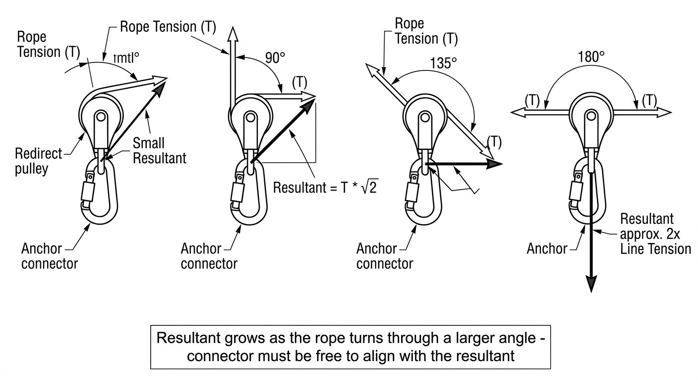
The connector at a redirect carries the resultant of two rope tensions, not one. The resultant depends on the angle the rope turns through: a small deviation adds little, a right-angle turn produces a resultant noticeably higher than the line tension, and a full 180-degree turn — a pulley at the top of a simple haul — produces roughly twice the line tension in the direction of the anchor. Combine that with the mechanical advantage of the haul system and a modest pull at the hauling end becomes a substantial force at the head connector.
Two practical consequences:
- Size and shape the head-pulley connector for the highest load in the system, not for the load the haulers feel.
- Make sure the connector can align with the resultant, not with either individual rope. A directional connector that cannot swing into line with the resultant is a cross-loaded connector.
Never substitute a connector for a pulley
Running a loaded rope directly over a connector as an improvised redirect is a persistent field habit and a bad one. Friction is high, so the haul team loses much of its mechanical advantage; the rope sheath is abraded at a single point; and the connector itself develops a groove that becomes a stress concentration and a rope-cutting edge. If a direction change is needed, use a pulley or a purpose-made ring designed for a running rope. A connector’s job is to join components, not to guide rope under load.
Field checks before the first haul
Build the system, tension it lightly, and look at every connector before committing the load:
- Gate closed, sleeve fully engaged — confirmed by sight and by touch, not by memory.
- Load path running spine to basket, with nothing bearing on gate or nose.
- Pulley free to rotate into line with the load, and rope not trapped between connector and cheek plate.
- One item per connector wherever the layout allows; a rigging plate if it does not.
- No possibility of the connector being levered against the anchor, a structural edge or the pulley body as the load moves.
Under load, re-check that nothing has migrated. A connector that was correctly oriented on a slack system can rotate as tension comes on, particularly where slings are stiff or anchors are tight. The generic version of this procedure — applicable to any connector pairing, not just pulleys — is set out in checking connector compatibility: a field method before you clip in.
Inspection: what hauling wear looks like
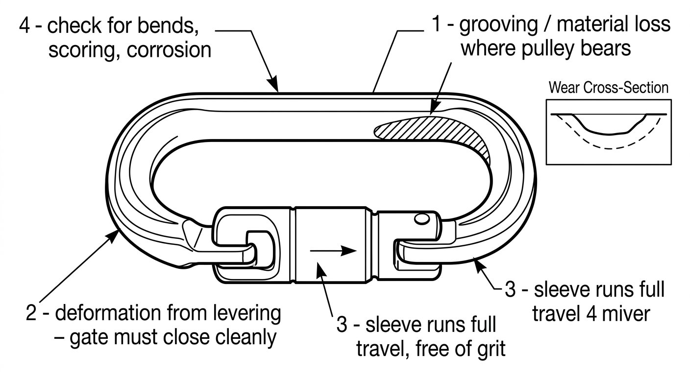
Hauling connectors accumulate a specific wear pattern that differs from lanyard-end hardware. Look for a bright, flattened or grooved bearing surface where the pulley hole has worked against the connector body; measurable material loss there is a retirement criterion, since the remaining cross-section carries the whole load. Check that the gate closes cleanly and that the nose has not been deformed by levering, and confirm the sleeve runs freely along its full travel. Grit trapped in an auto-lock mechanism after confined-space work should be flushed and the action re-tested before the connector goes back in a load path.
Takeaway
For pulley attachments, choose a locking oval whose cross-section genuinely fits the attachment hole, dedicate it to the pulley alone, and let the pulley align itself with the load. Choose steel where wear and grit dominate, and aluminium where weight does. Size the head and redirect connectors for the multiplied load, never for the effort the haul team feels. Further technique notes on system hardware and procedure are collected on the rope access and confined space hub.
Frequently asked questions
Why is an oval connector usually recommended for pulleys?
An oval body is symmetrical, so a pulley hung on it tends to stay on the connector's centre line and the load runs down the major axis from spine to basket. Asymmetric shapes push the pulley toward the narrow end, and wide pear-shaped bodies let it slide and rotate as the direction of pull changes during a haul.
Can a pulley, a rope clamp and a sling share one connector?
It should be avoided. Three items in one connector produce loads pulling in three directions, and connector ratings apply to major-axis loading with the gate closed. Use a double pulley with a becket, a progress-capture pulley, or a rigging plate that gives each component its own connector.
Should hauling connectors be screw-lock or auto-lock?
Screw-lock suits connections built once and left closed for the job, provided the sleeve is checked by sight and touch and re-checked during the shift. Auto-lock is better where the connector is opened and closed repeatedly or handled with gloves, but has more mechanism to jam with grit, ice or mud.
Is it acceptable to run a rope directly over a connector instead of a pulley?
No. Friction is high, so the haul team loses much of its mechanical advantage, the rope sheath is abraded at a single point, and the connector develops a groove that becomes both a stress concentration and a rope-damaging edge. Use a pulley or a purpose-made ring for a running rope.
Steel or aluminium for hauling connectors?
Aluminium is the default for hardware technicians carry and for systems built and struck each shift. Steel is worth the weight for fixed or semi-permanent installations, high-cycle use, and abrasive environments such as shafts and sewers. Remember that steel components wear aluminium ones, so inspect the aluminium side of a mixed pairing closely.
How much load does the connector at the top redirect actually see?
It carries the resultant of the rope tensions either side of the pulley, which grows as the rope turns through a larger angle and approaches roughly twice the line tension at a full 180-degree turn. That resultant is then on top of whatever mechanical advantage the haul system provides, so the head connector should be sized for the highest load in the system.
Need this as a document you can issue? The template library gives you the risk assessments, permits and inspection logs in editable form — and employer plans cover a whole team with completion records.