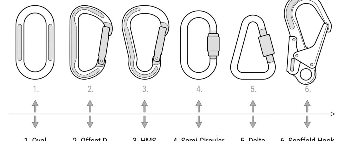
Safety / Tips and Tricks / Rope access and confined space
Activity 01 · Rope access
Connector Shapes and Where Each Belongs
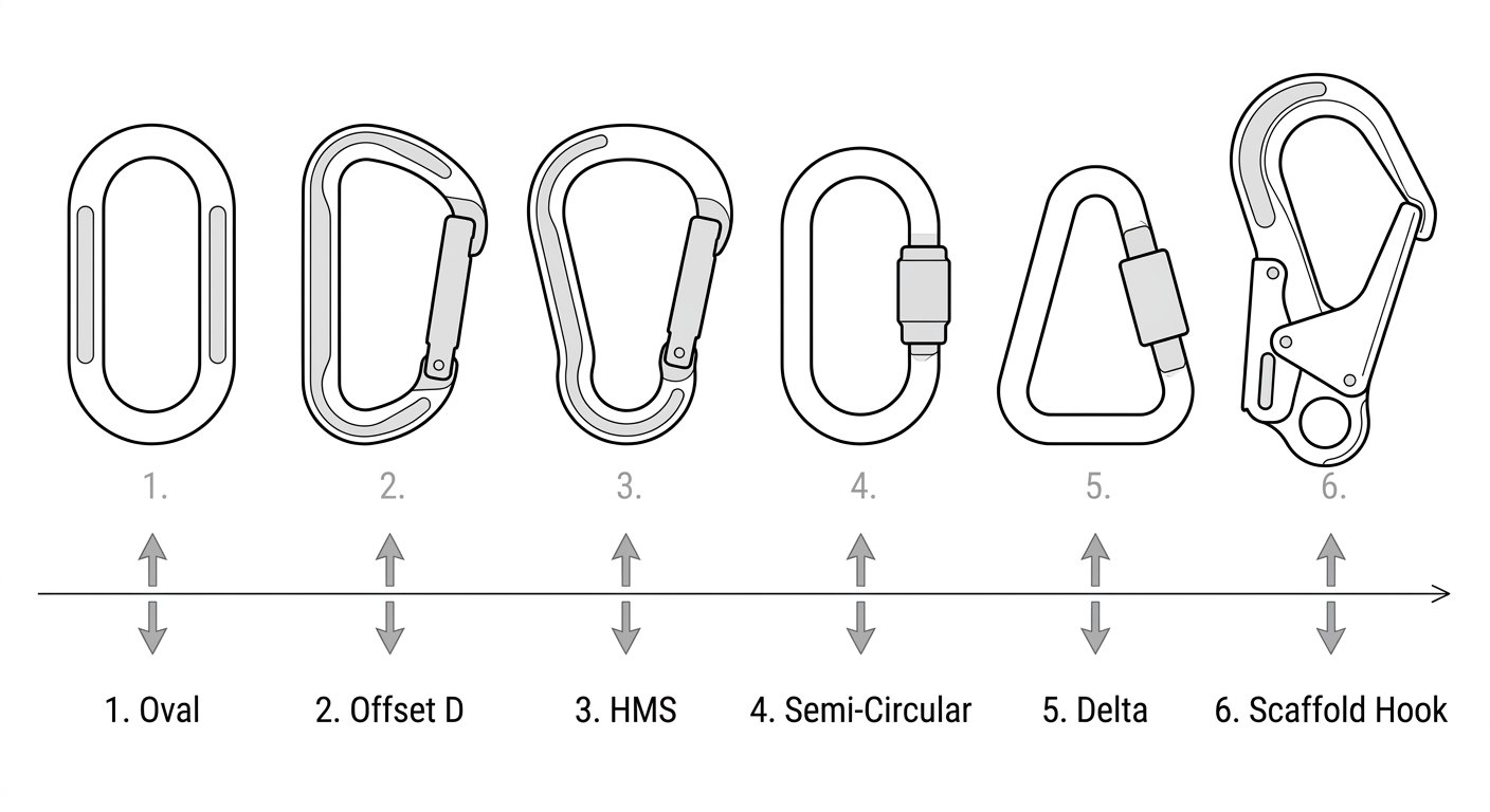
A connector's shape is not cosmetic. It decides where the load sits inside the frame, whether an attached device stays aligned under load, how much room there is at the basket for a hitch or a second connection, and how easily the gate can be pressed against something it should never touch. Two connectors with the same locking system, the same alloy and the same marked strength can behave very differently on a job simply because one is an oval and the other is an offset D. This note works through the main shapes used in rope access and confined-space work and states what each is actually for.
Why shape changes the load path
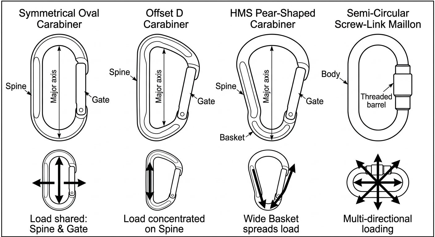
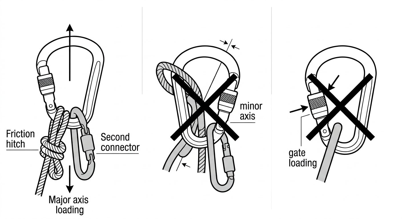
Every connector is designed to be loaded along its major axis – spine to gate, in line. Shape governs how reliably that happens. A symmetrical frame splits load evenly between spine and gate side; an asymmetrical frame biases it onto the spine, which is the stronger, solid side. A wide basket lets several items sit side by side but also lets them wander; a narrow basket keeps one item captive but crowds anything else you try to add.
Connectors for fall protection and work at height are certified under EN 362 (Connectors for Fall Protection), which sorts them into classes by intended use rather than purely by outline – basic connectors, multi-use connectors intended to accept loading on more than one axis, termination connectors that hold a predetermined orientation, anchor connectors, and screw-link (quick link) connectors. Climbing-standard connectors carry a related set of type letters (oval, HMS, directional, quick link and so on). The class or type marking tells you more about correct use than the silhouette does, so read it before assuming a shape’s purpose.
Oval: symmetry for devices that must stay centred
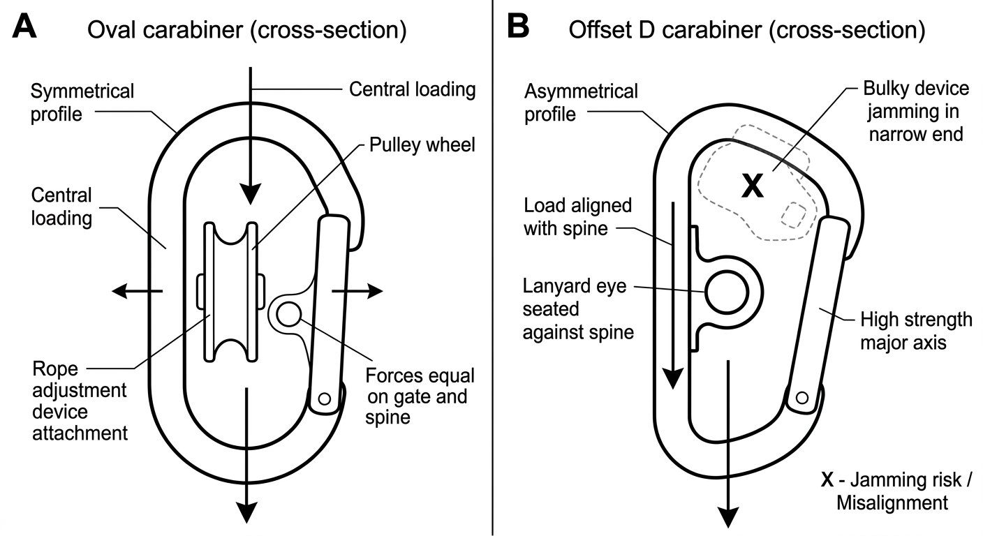
The oval is the conservative shape. Because spine and gate side mirror each other, whatever you clip in tends to settle in the middle of the connector and stay there when the load comes on. That is exactly what you want with pulleys, swivels, rigging plates, and rope adjustment devices working to EN 12841 (Rope Access Adjustment Devices), where a device that slides to one side ends up loading the connector at an angle or bearing on the gate.
The trade-off is efficiency: a symmetrical frame shares the load between spine and gate side, so ovals are typically rated lower on the major axis than a comparable D of the same size and mass. Choose an oval when predictable alignment matters more than headline strength – which, in most rope-access hardware chains, it does.
D and offset D: strength on the spine
A D-shaped frame pushes the load toward the spine. The offset (asymmetric) D takes this further, narrowing the top end so the connector is at its widest where the load actually sits. For the same weight of material, these are usually the strongest and most compact shapes available, which is why they dominate lanyard and mobile fall-arrester end connections and general anchor-side use – see the note on choosing a fall-arrest lanyard type for how the terminal connector fits into that decision.
The narrow top end is also the limitation. There is little room in the basket, so a D is a poor choice where you need to stack two or three connections, and it is unforgiving if the attached item is bulky. Use a D for a single, in-line connection; use something wider when the connection point has to share.
HMS / pear: the wide basket
The HMS or pear shape has a deliberately generous rounded end. That volume does three things: it accommodates a friction hitch with room to move, it lets a bulky descender body or a hitch plus a backup sit together without jamming, and it gives a large radius for rope to run over. In confined-space and rescue rigging, the pear is the usual choice at a master point where several items converge and at the harness attachment when a bulky device has to be introduced.
The same width is the shape’s weakness. A wide basket allows contents to shift, and a connector loaded across its short axis or with a load bearing on the gate is dramatically weaker than the marked major-axis figure. Pear connectors intended for a working attachment should therefore usually be a large-capacity locking model, and where the connector carries a descender the shape and locking choice need to be considered together – the article on choosing a connector for a descender covers that combination in detail.
Semi-circular and delta maillons: semi-permanent, multi-axis attachment
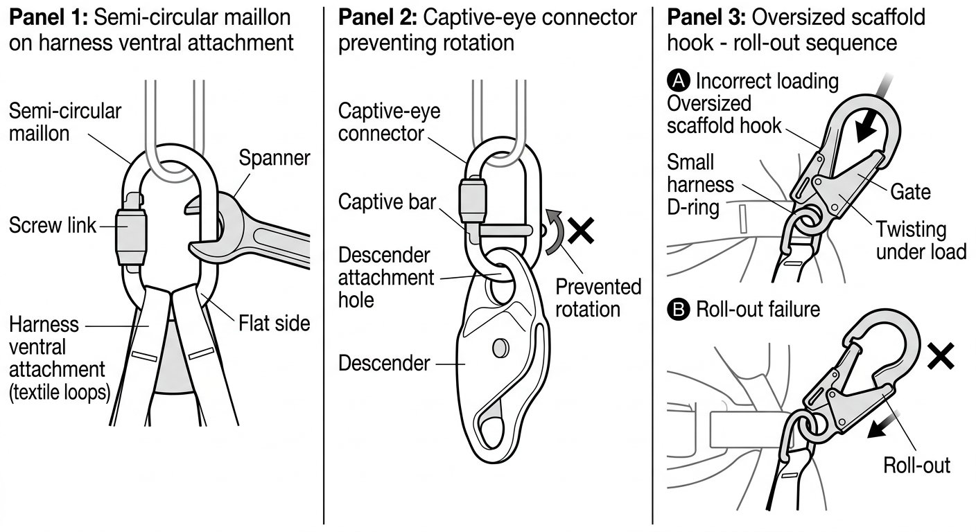
Screw links – semi-circular maillons and delta (triangular) maillons – have no gate mechanism. The barrel is threaded closed by hand and tightened with a spanner, and they are treated as semi-permanent parts of an assembly rather than connections made and broken during a shift. Their shapes exist for specific geometry:
- Semi-circular maillon: the flat side beds against the two loops or textile bars of a ventral or sternal attachment, keeping both legs of the harness attachment properly spread and holding the maillon square rather than letting it rotate.
- Delta maillon: the triangular frame suits three-way connections, typically where two harness loops and one device must all sit on the same point.
Because they are closed by a threaded barrel and are intended to stay in place, screw links tolerate the multi-directional loading that harness attachment points impose better than a snapgate does. They belong on attachment points defined by the harness manufacturer under EN 361 (Full Body Harnesses) or on a sit-harness bridge – not as a connector you clip and unclip. Check that the barrel is fully closed and tight as part of harness donning; the fit-check routine for a full body harness is the natural place to do it.
Directional and captive-eye connectors: holding orientation
Some shapes exist purely to stop a connector rotating. A captive-eye connector has a bar or narrowed slot at one end that traps the textile or the device’s attachment hole in a fixed position; a directional connector is asymmetric in a way that only allows correct assembly. Both are the answer to the same problem: a device that has walked around the connector until it is loading the gate, or a lanyard eye that has crept onto the minor axis.
Typical uses are the moving end of a lanyard, the attachment of a descender or backup device where the orientation must be maintained, and any connection you cannot watch continuously. Where the connector’s job is to keep something oriented, that intent is reflected in its certification class – termination connectors are specifically those designed to be used with a predetermined orientation, and they should be assembled the way the manufacturer’s instructions show.
Hooks: shape as a size problem
Snap hooks, and the large scaffold, rebar and pipe hooks used on lanyard ends, are shaped around what they clip to rather than around the load path. A large-opening hook lets a worker connect to structural steel, scaffold tube or rebar cages without needing a separate anchor sling – a real advantage in confined and cluttered spaces. The geometry brings two specific risks:
- Roll-out: a large hook clipped to a small, thick or heavily loaded ring can rotate until the gate is forced open. Never clip an oversized hook to a small D-ring, and never clip two hooks into the same small ring.
- Gate and nose loading: hooks with a long nose are vulnerable if the load ends up on the nose or across the gate rather than in the throat, seated against the spine.
The general rule is that the connector must match the size and shape of the thing it is clipped to – large hooks for structural members, small connectors for harness rings and device holes.
Matching shape to job: a short summary
- Pulley, swivel, rope adjustment device, rigging plate: oval, for centred and predictable loading.
- Single in-line connection where strength and compactness matter: D or offset D.
- Master point, friction hitch, bulky descender, multiple connections: HMS / pear, locking, large capacity.
- Harness ventral, sternal or bridge attachment, semi-permanent assemblies: semi-circular or delta maillon, spanner-tightened.
- Anything that must not rotate out of position: captive-eye or directional connector, assembled per instructions.
- Anchoring to structural steel, scaffold tube or rebar: large-opening hook, sized so roll-out is impossible.
Checks that shape does not replace
No shape protects against being clipped wrong. Before loading any connection, confirm three things: the load runs spine-to-gate along the major axis, nothing is bearing on the gate or nose, and the gate is fully closed and locked. Read the connector’s markings – the class or type letter and the marked axis strengths tell you what geometry the maker designed for. Shape and locking are separate decisions that interact, and the comparison of screw-lock, two-stage and three-stage auto-lock systems is worth reading alongside this note.
Takeaway: pick the shape from the load path, not from what is on the rack. Symmetry for devices that must stay centred, asymmetry for strength on a single in-line pull, width for crowded master points, threaded links for attachment points that stay assembled, and captive geometry wherever orientation matters. Further technique notes are collected on the rope access and confined space hub.
Frequently asked questions
Why choose an oval connector if a D of the same size is stronger?
Because alignment often matters more than peak strength. An oval's symmetry means pulleys, swivels and rope adjustment devices settle in the centre and stay there under load, instead of sliding to one side and loading the connector at an angle or against the gate. The D's advantage is strength and compactness for a single in-line pull.
Can I use a screw-link maillon as an everyday connection I clip and unclip?
No. Screw links are intended as semi-permanent parts of an assembly, closed by hand and tightened with a spanner, typically on harness attachment points or fixed sub-assemblies. If a connection has to be made and broken during a shift, use a locking connector designed for that.
What is roll-out and which shapes are prone to it?
Roll-out is when a connector rotates inside the item it is clipped to until the gate is forced open. It is mainly a risk with large-opening snap, scaffold and rebar hooks clipped to something too small or too thick, such as a harness D-ring, or when two hooks share one small ring. Match the hook size to the attachment point, and never clip two hooks into the same small ring.
Which shape belongs at a rescue or rigging master point?
Usually a large-capacity locking pear (HMS), because the wide rounded basket accepts several connections, a bulky device, or a friction hitch with room to move. The trade-off is that contents can shift, so the connector's alignment should be checked before and during loading.
How do I know whether a connector is meant to hold a fixed orientation?
Look at the markings and the manufacturer's instructions rather than the outline. EN 362 distinguishes connectors by class, including termination connectors intended for use in a predetermined orientation; captive-eye bars and directional frames are the physical expression of that intent. Assemble them exactly as the instructions illustrate.
Does picking the right shape remove the need to check anything else?
No. Whatever the shape, confirm that the load runs along the major axis from spine to gate, that nothing bears on the gate or nose, and that the gate is fully closed and locked. Shape reduces the chance of a bad load path; it does not guarantee one.
Need this as a document you can issue? The template library gives you the risk assessments, permits and inspection logs in editable form — and employer plans cover a whole team with completion records.