Safety / Tips and Tricks / Rope access and confined space
Activity 01 · Rope access
Choosing Connectors for Anchor Rigging: Shape, Closure and Correct Loading
The connector at the anchor end of a system is the one most often chosen by whatever is left on the harness rack, and the one most exposed to being loaded in a way it was never designed for. Anchors are rarely as tidy as the pictures: a connector may end up on a wide structural eye, a scaffold tube, a stainless ring, a textile sling, a rigging plate, or two of these at once. Choosing the connector for anchor rigging is mostly a question of geometry — will this connector sit correctly on this anchor, under load, and stay that way when the load direction changes.
This note covers how to read the anchor interface first, how to choose shape and closure for the job, and the loading faults that anchor-side connectors are most prone to.
What the anchor-side connector actually has to do
An anchor connector has three jobs, and they conflslightly with each other:
- Transfer the load along its major axis. Connectors to EN 362 (Connectors for Fall Protection) are typically rated at a minimum of 15 kN along the major axis with the gate closed and locked. Strength across the minor axis, or with the gate open, is substantially lower and is what the manufacturer marks separately — treat those values as failure conditions to avoid, not as a working reserve.
- Stay aligned as the load direction moves. A rope-access anchor sees the load direction change every time the technician moves, transfers, or gets pulled sideways. The connector has to be free to rotate into line.
- Not open unintentionally. Either because it can’t (a fully closed screw-link) or because its locking mechanism resists the specific ways gates get nudged open against structure.
EN 362 recognises several classes, and the class marking is the quickest way to check that a connector was designed for this position: Class A connectors are intended to attach directly to a specific type of anchor, Class B are basic connectors, Class M are multi-use connectors loadable along both major and minor axes, Class T are termination connectors intended to hold a fixed load direction, and Class Q are screw-links closed by a threaded sleeve. A connector marked only for a narrow use case does not become general-purpose because it happens to be the right size.
Read the anchor before you choose the connector
The first question is not “which connector” but “what am I clipping to, and how wide is it”. Three interfaces cause most problems:
- Wide or flat anchors. A structural eye plate, a broad forged eye, or a flat bar can be wider than the inside of the connector’s basket. The connector then bears on the anchor at two points near the ends of its frame and is levered outward rather than pulled along its spine. This is a bending load on a component designed for tension.
- Large-diameter anchors. A big scaffold tube or a thick structural member can fill the connector to the point where the gate cannot close, or where the frame sits jammed and cannot align. Check the internal clearance with the gate closed, not just that the gate can be got shut.
- Sharp or rough anchors. Corroded steelwork, cut edges and weld spatter chew the anchor-side contact area of an aluminium connector quickly. This is a wear and inspection problem as much as a strength one.
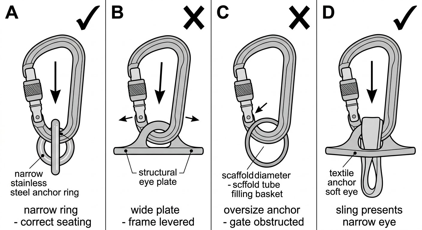
If the anchor is wider than the connector will comfortably accept, the answer is almost never a bigger connector. It is a textile anchor sling, a round sling, or a purpose-made anchor strap that presents a soft, narrow, correctly oriented eye for the connector to sit in. That converts an awkward metal-on-metal geometry into one the connector was designed for.
Choosing the shape
Shape choice at the anchor follows the number of things attached and how much freedom the connection needs. The general logic is covered in more detail in the note on connector shapes and where each belongs; applied to anchor rigging:
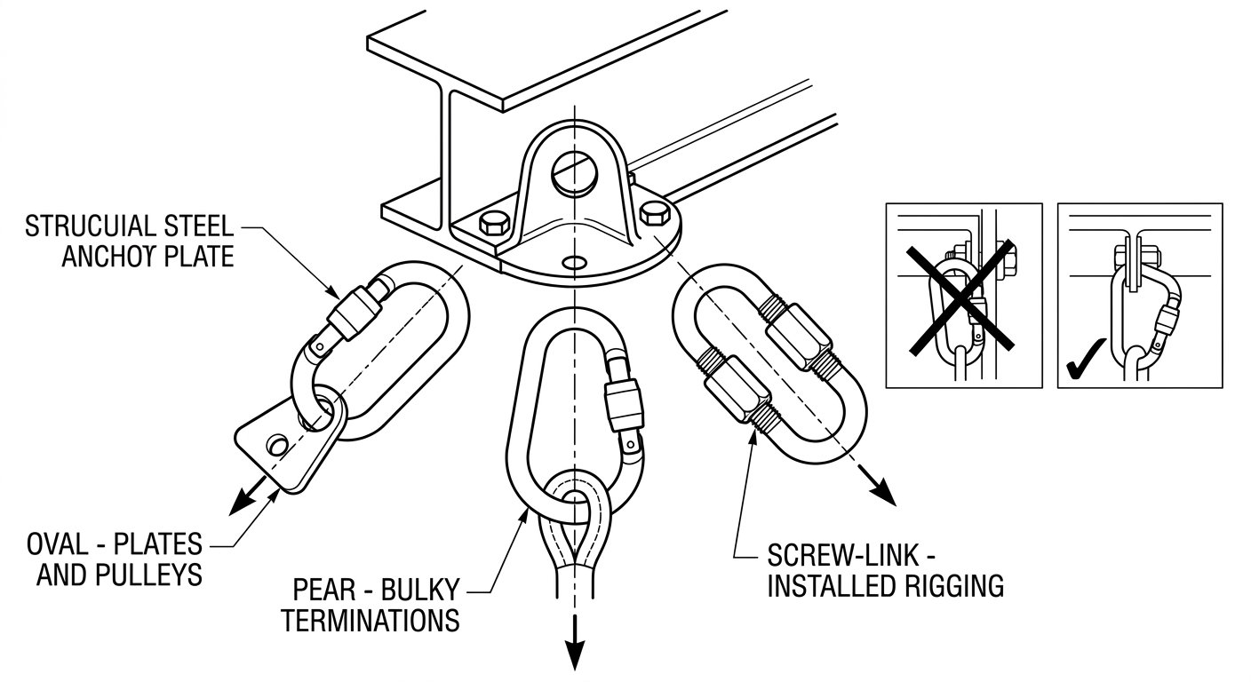
- Pear/HMS shapes give a wide basket at the top, which suits an anchor connector that has to accept a bulky item — a knotted rope termination, a descender, or a sling eye — and lets it find its own position. The trade-off is that the load can migrate within that wide basket, so a pear-shaped connector is a poor choice when several items must be kept separated.
- Oval shapes keep the load centred and symmetrical, which is why they are the standard choice for pulleys, rigging plates and connections where the item must stay put along the spine. They have the smallest usable basket for their size.
- D shapes push the load towards the spine and suit single-direction loading — a good anchor-side choice when the load path is fixed and known.
- Captive-eye or bar-fitted connectors hold the attached item at the correct end of the connector. At an anchor where an attachment tends to creep towards the gate, this is a genuine fix rather than a convenience.
Choosing the closure: how often will this be opened?
Closure choice at the anchor is driven by access frequency, not by preference. The comparison of screw-lock, two-stage and three-stage auto-lock systems applies directly here:
- Opened repeatedly during the shift — for example a rebelay or deviation a technician clips and unclips on every pass — favours an auto-locking connector. A screw sleeve that has to be undone and redone dozens of times will eventually be left unscrewed.
- Set up once and left for the day suits either an auto-lock or a screw-lock, provided the screw sleeve is checked closed after rigging and re-checked at each visit. Screw sleeves in this position should be verified by sight and touch, not assumed.
- Semi-permanent or installed rigging — a fixed anchor that will not be dismantled at the end of the job — is the case for a screw-link (Class Q). Screw-links only reach their rated strength with the sleeve fully closed, threads completely engaged, and are normally tightened with a spanner rather than by hand. They are not intended for connections that get opened and closed routinely.
- Anchors close to structure deserve a locking mechanism that resists being pushed open by contact with the structure itself. A three-stage sleeve is harder to defeat by pressure and rotation against a beam than a simple sprung sleeve.
Steel or aluminium at the anchor
Aluminium connectors are lighter and are what most technicians carry on the harness. At the anchor, steel earns its weight in specific cases: rigging that stays installed and is exposed to weather, anchors on abrasive or corroded steelwork, connectors that will be loaded repeatedly in the same spot over a long job, and rescue or hauling anchors where a metal-on-metal interface will see movement under load. Aluminium wears faster where it contacts hard steel, and wear at the anchor-side contact patch is the most common reason an anchor connector is retired.
Mixing metals is not a problem in itself; the practical point is that whichever component is softer will take the wear, so put the wearing surface where you can see and inspect it.
The loading faults specific to anchor connectors
Most anchor-side failures are geometry failures, and they repeat:
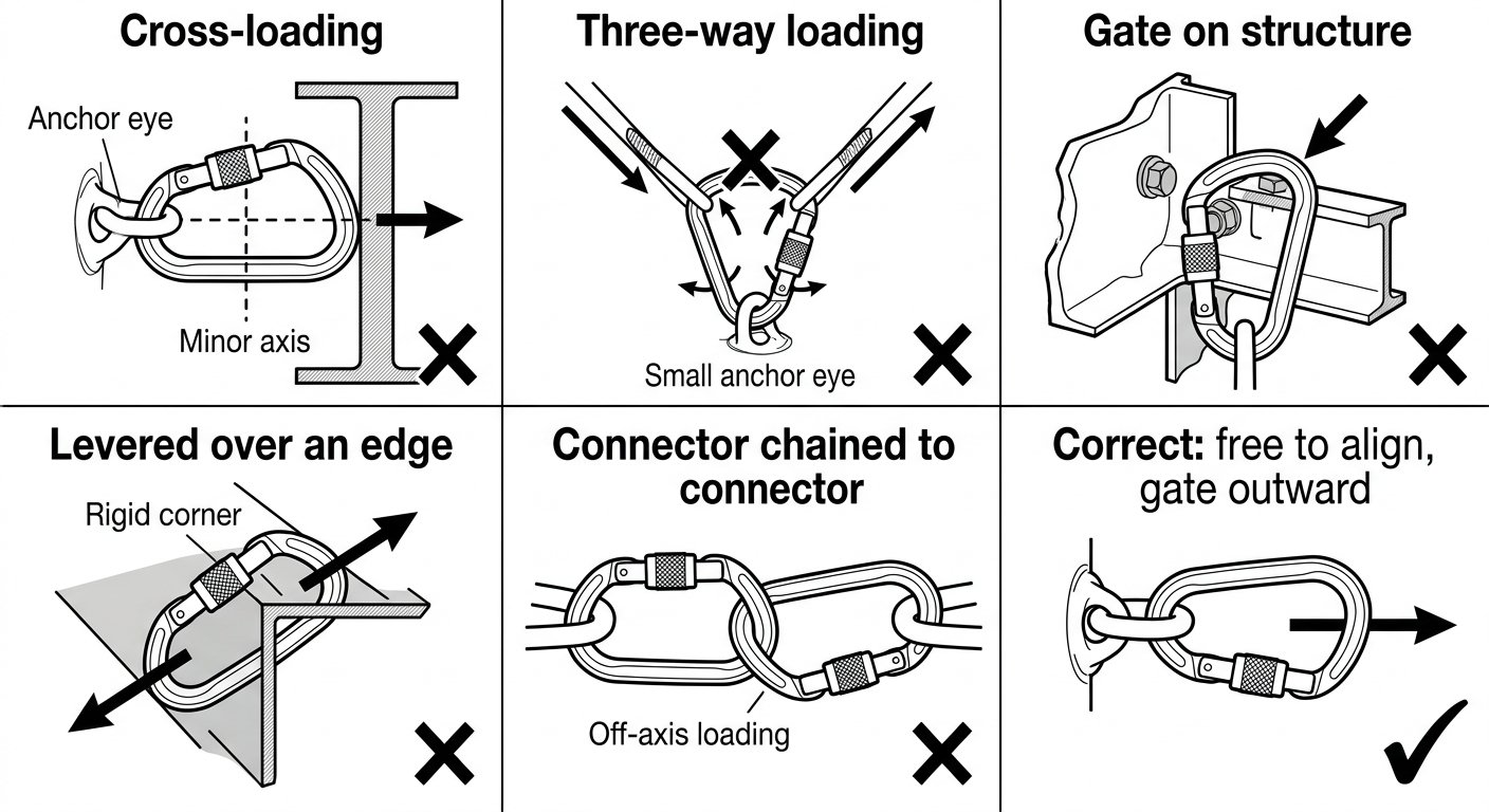
- Cross-loading. The connector ends up loaded across its minor axis because the anchor holds it flat against a surface or because an attached item sits sideways in the basket. Minor-axis strength is a fraction of major-axis strength.
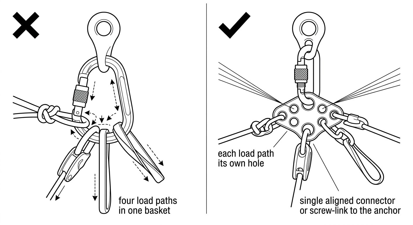
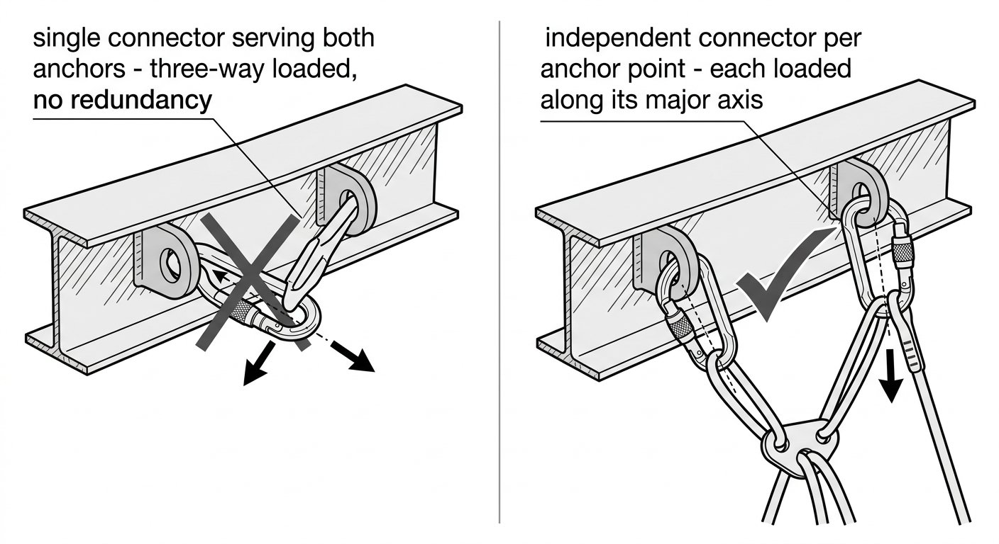
- Three-way loading. Two load paths pulling in different directions plus the anchor makes a triangle, and the connector is spread rather than pulled. This is a very common result of clipping two independent legs into one anchor connector.
- Gate loaded against structure. The gate rests on a beam, edge or bolt head, and the frame is loaded so that the structure presses on the gate or the locking sleeve. Rig so the gate faces away from the structure and is free.
- Levering over an edge. The connector is trapped so that a rigid part of the anchor bears on the frame at an angle. Anything that prevents the connector from rotating freely is a candidate for this.
- Connector chained to connector. Two connectors clipped directly to each other cannot align reliably; each tends to sit in the other’s radius and load off-axis. Use a sling, a ring or a rigging plate to separate them.
The field routine for catching these before loading is the same one described in the note on checking connector compatibility before you clip in: put the connection in the position it will actually take under load, pull it in the working direction, and look at where the contact points end up.
When to add a rigging plate instead of another connector
As soon as an anchor has to serve more than two load paths — a working line, a backup, a haul line, a deviation — the anchor connector becomes the wrong tool for spreading them. A rigging plate gives each item its own hole, keeps the load paths separated and predictable, and removes the three-way loading problem entirely. The plate itself is normally connected to the anchor with a single, correctly aligned connector, or with a screw-link if the arrangement stays installed.
The same reasoning applies to redundant anchors. Two independent anchor points should have two independent connectors; a single connector clipped into two anchor eyes is one component serving as the sole link for both, and it is being three-way loaded while doing it.
Marking, inspection and what to retire
Anchor connectors accumulate damage in a distinctive pattern: a worn groove or flat on the anchor-side radius of the frame, sleeve threads clogged with grit or paint, and gate springs stiffened by corrosion or debris. On each inspection, check that the gate closes fully and unaided, that the locking sleeve engages completely, that the frame has no grooves, gouges or deformation at either contact radius, and that the class and strength markings are still legible. A connector whose markings can no longer be read cannot be verified as suitable for the position it is in.
Retire connectors with visible frame deformation, a gate that does not seat and lock without help, or wear that has reduced the section at a contact radius. In an installed anchor this matters more than on the harness, because a fixed connector may go months between close looks.
Selection summary
- Look at the anchor: width, diameter, edges. If the connector cannot sit and rotate freely, add a sling rather than a bigger connector.
- Choose the shape by what the connector holds — oval for plates and pulleys, pear for bulky or mixed items, D for a fixed load direction, captive-eye where an item creeps.
- Choose the closure by access frequency — auto-lock for repeated clipping, screw-lock for once-per-shift rigging, screw-link fully tightened for installed anchors.
- Choose the material by exposure and wear — steel for installed, abrasive or high-cycle anchors.
- Confirm alignment under a pull in the working direction, with the gate facing away from the structure.
- Use a rigging plate as soon as more than two load paths meet, and give each independent anchor its own connector.
For the connector-side fundamentals behind these choices — gate types, axes and how strength markings relate to real loading — see connector basics: gates, axes and loading, and the rest of the rope access and confined space technique notes.
Frequently asked questions
Can I clip two independent anchor legs into the same anchor connector?
It is best avoided. Two legs pulling in different directions turn the connector into a three-way loaded component, spread rather than pulled along its spine, and it becomes a single link serving both anchors. Give each anchor point its own connector, and bring the legs together at a rigging plate if they need a common attachment.
When should I use a screw-link (Class Q) instead of a carabiner at the anchor?
Use a screw-link where the connection is installed and will not be opened routinely — a fixed anchor, a permanently rigged plate, a semi-permanent deviation. Screw-links only reach their rated strength with the sleeve fully closed and threads completely engaged, and are normally tightened with a spanner. For connections opened during the shift, a carabiner with an auto-locking or screw sleeve is the appropriate choice.
Is an auto-locking connector always better than a screw-lock at an anchor?
Not always — it depends on how often the connector is opened and how exposed it is. Auto-lock suits anchors that are clipped and unclipped repeatedly, because a screw sleeve in that position tends to be left undone. A screw-lock is acceptable for rigging set up once and verified closed, and multi-stage locking sleeves are preferable where the gate could be nudged against structure.
What do I do if the anchor is too wide for my connector?
Do not simply reach for a larger connector — a wide flat anchor tends to bear on the ends of the frame and lever it rather than load the spine. Fit a textile anchor sling, round sling or anchor strap through the anchor so it presents a narrow eye, and clip the connector into that eye instead.
Should anchor connectors be steel or aluminium?
Aluminium is fine for most connectors carried and used on a single job. Steel is worth its extra weight for anchors that stay installed, sit on abrasive or corroded steelwork, or see repeated loading and movement in the same contact spot, because wear at the anchor-side radius is the usual reason an anchor connector is retired.
What should I check on an installed anchor connector during inspection?
Check that the gate closes fully and unaided, that the locking sleeve engages completely with clean threads, that the frame has no grooves, gouges or deformation at either contact radius, and that class and strength markings are still legible. Retire connectors with frame deformation, a gate that will not seat and lock by itself, or wear that has thinned a contact radius.
Need this as a document you can issue? The template library gives you the risk assessments, permits and inspection logs in editable form — and employer plans cover a whole team with completion records.