Safety / Tips and Tricks / Rope access and confined space
Activity 01 · Rope access
How and Why to Use a Fall-Arrest Lanyard
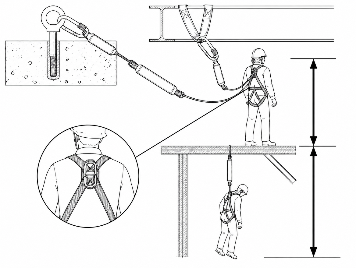
An energy-absorbing lanyard is the most commonly issued piece of fall-arrest connecting equipment on European sites, and the most commonly misused. Get the anchor height, the clearance below the working position and the harness attachment point right, and it limits the force on the body to a survivable level. Get any one of them wrong and the lanyard either does nothing useful or transfers a fall load the wearer's body was never meant to take. This article sets out what a fall-arrest lanyard is under EN 354 and EN 355, how it must be connected and anchored, how to calculate the clearance it needs, and what takes it out of service.
What a fall-arrest lanyard is under EN 354 and EN 355
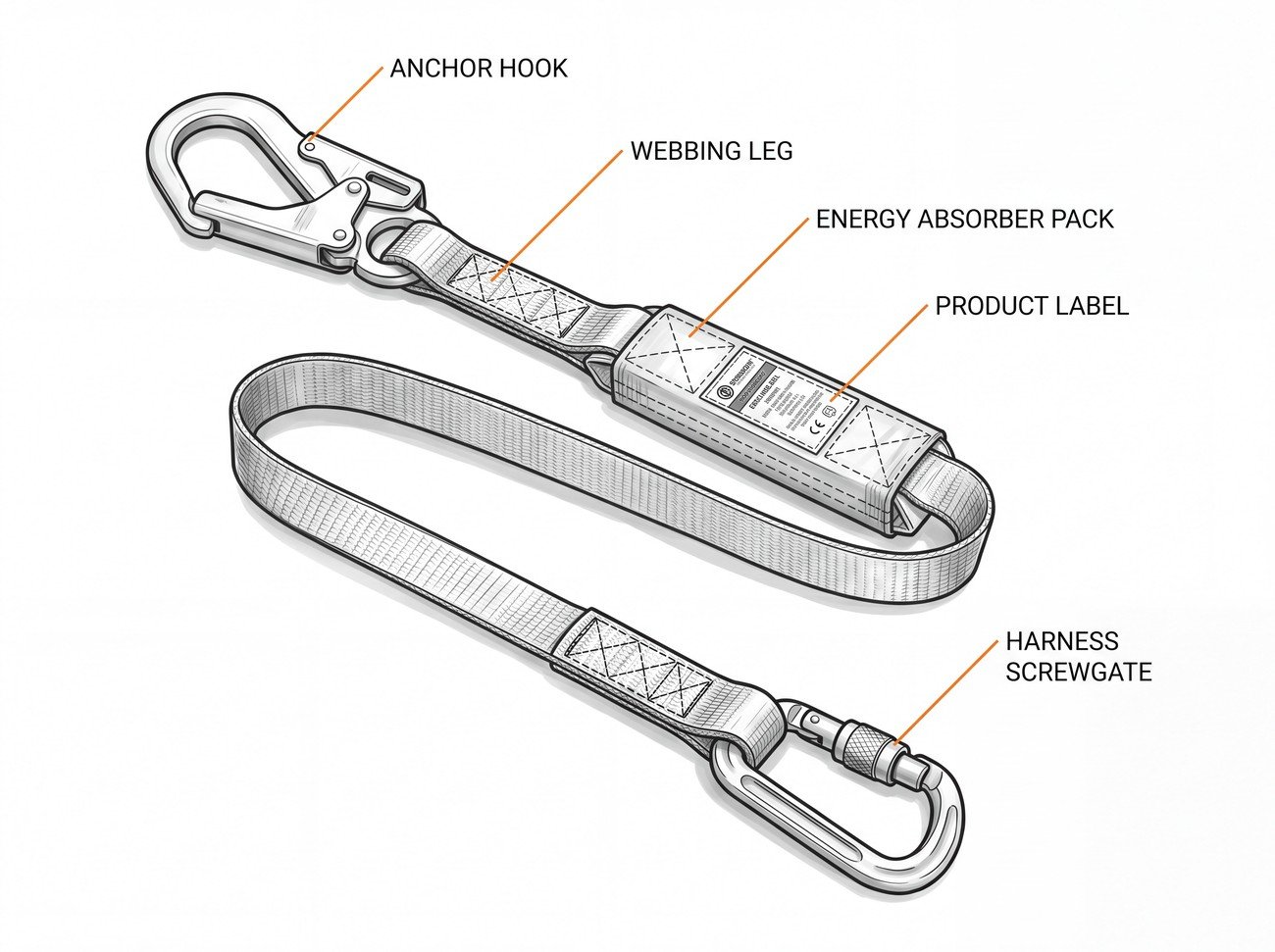
A fall-arrest lanyard is a connecting subsystem between a full body harness and an anchor point. In practice, two different products are described by that phrase, and only one of them is a fall-arrest component on its own:
- EN 354 lanyard – webbing, rope or wire rope with terminations, maximum length 2 m. On its own it is a connecting element, not a fall-arrest system. Used alone in a fall, it transmits essentially the full arrest force to the wearer.
- EN 355 energy absorber – a tear-webbing pack or comparable device that deploys under load to limit the arrest force. Under EN 355 the arrest force must not exceed 6 kN, and the total length of the assembly – energy absorber, lanyard and connectors, including deployment – must not exceed 2 m before deployment.
What most workers call a “shock-absorbing lanyard” is the combined assembly: an EN 355 absorber pack permanently joined to an EN 354-type leg, with EN 362 connectors at each end. That assembly, together with an EN 361 full body harness and an anchor conforming to EN 795, forms a fall-arrest system in the sense of EN 363.
Three related products are frequently confused with it and are not substitutes:
- EN 358 work positioning lanyards connect to the side attachment points of a belt or harness. They are for holding the user in position, not for arresting a fall.
- EN 360 retractable type fall arresters arrest earlier in the fall and generally need less clearance, but have their own anchor and edge restrictions.
- EN 353-2 guided type fall arresters on a flexible anchor line are for climbing and vertical movement, not for general tethering.
Why the energy absorber matters more than the webbing
A person falling 2 m generates far more force than the human skeleton and soft tissue tolerate if that fall is stopped abruptly. The purpose of the EN 355 pack is not to stop the fall, it is to slow it: the stitching tears progressively, extending the stopping distance and capping peak force at or below 6 kN. Everything else follows from that. The absorber needs travel to deploy, so the system needs vertical space – which is why clearance, not webbing strength, is the usual failure point in real incidents.
Rated user mass matters here. EN 355 was historically verified with a 100 kg test mass; many current products are certified for a wider range, often up to 140 kg including tools and equipment. That figure appears on the product label and in the manufacturer’s instructions, and it is the figure that governs – total kitted-out weight, not body weight alone.
Connect only to the fall-arrest attachment points of an EN 361 harness
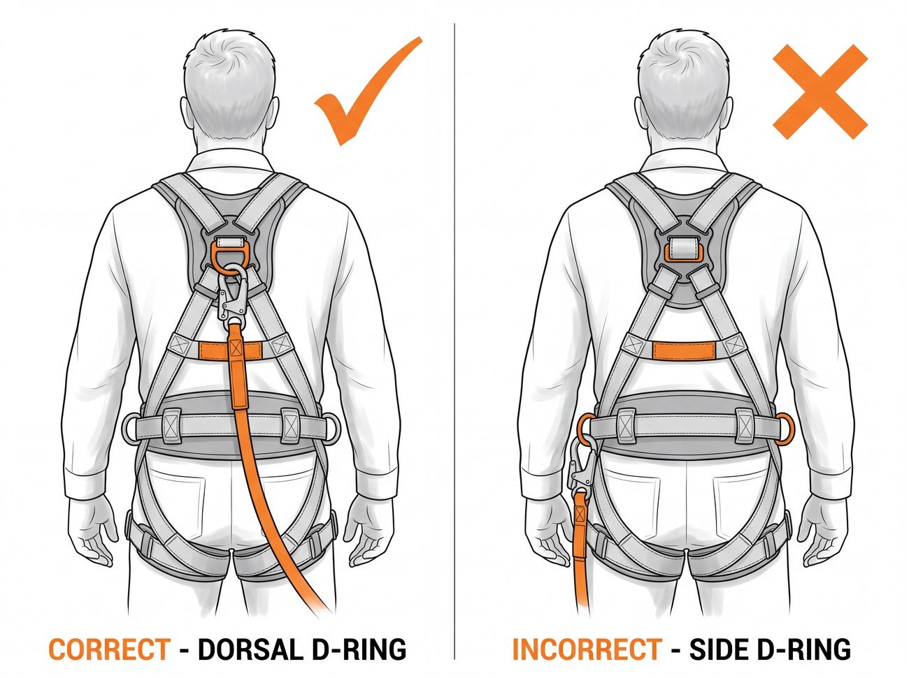
An EN 361 full body harness has designated fall-arrest attachment points, marked with a capital A. These are normally a dorsal (rear) D-ring or webbing loop between the shoulder blades, and in many models a sternal (front) attachment. Where two elements must be used together to form one attachment point, they are marked A/2 and both must be connected.
The dorsal point is the default for fall arrest: it keeps the wearer roughly upright after arrest, keeps the lanyard out of the working zone, and avoids the head-forward posture that a front-only attachment can produce in a long fall. Side D-rings (EN 358) and ventral attachments on EN 813 sit harnesses are not fall-arrest points. Neither is a tool loop, a belt, or any point on the harness that is not marked A.
At the connector end, use the connector supplied or specified for the assembly. EN 362 classifies connectors by intended use – for example class A for direct attachment to a specific anchor type, class Q screwgate connectors whose sleeve must be fully tightened, class T terminations that hold the load in a fixed direction. A large scaffold hook is designed for structural members of a particular diameter; a small screwgate is not. Substituting one for the other changes the gate loading and the way the connector sits under load.
Anchor position: above the dorsal D-ring, and directly overhead
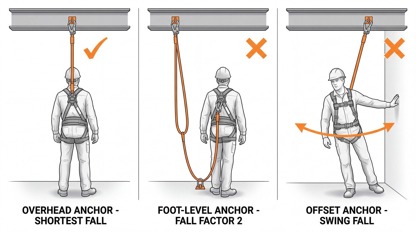
Anchor height determines fall distance, and lateral anchor position determines whether the wearer swings. Both are set before work starts, not adjusted afterwards.
Anchor above the dorsal attachment point keeps the fall short. Anchoring at foot level with a 2 m lanyard means a free fall of roughly twice the lanyard length before the absorber even begins to work – a fall factor 2 situation. Some energy absorbers are tested and approved for fall factor 2 use and some are not; that is stated in the manufacturer’s instructions, and it is not an assumption to make on site.
Anchoring off to one side creates a pendulum. In a swing fall the wearer travels sideways as well as down, and can strike structure, plant or the edge itself before the system takes load. The lanyard may also be dragged across an unprotected edge, where webbing can be cut through at loads far below its rated strength. Where an edge cannot be avoided, use equipment specifically tested for edge loading and follow the manufacturer’s stated edge conditions.
The anchor itself should conform to EN 795 for the relevant type – for example type A structural anchors, type B transportable anchors, type C flexible horizontal anchor lines – and be selected by someone competent to confirm it can take the loads generated by an arrested fall, including the additional load a horizontal line transfers to its end anchors. Structure that merely looks solid, such as handrail, conduit, cable tray or ductwork, is not an anchor unless it has been assessed as one.
Fall clearance: the calculation that decides whether the lanyard works
A 2 m energy-absorbing lanyard needs several metres of unobstructed space below the anchor. If that space is not there, the wearer contacts the lower level before the absorber has finished deploying, and the system has provided no protection at all.
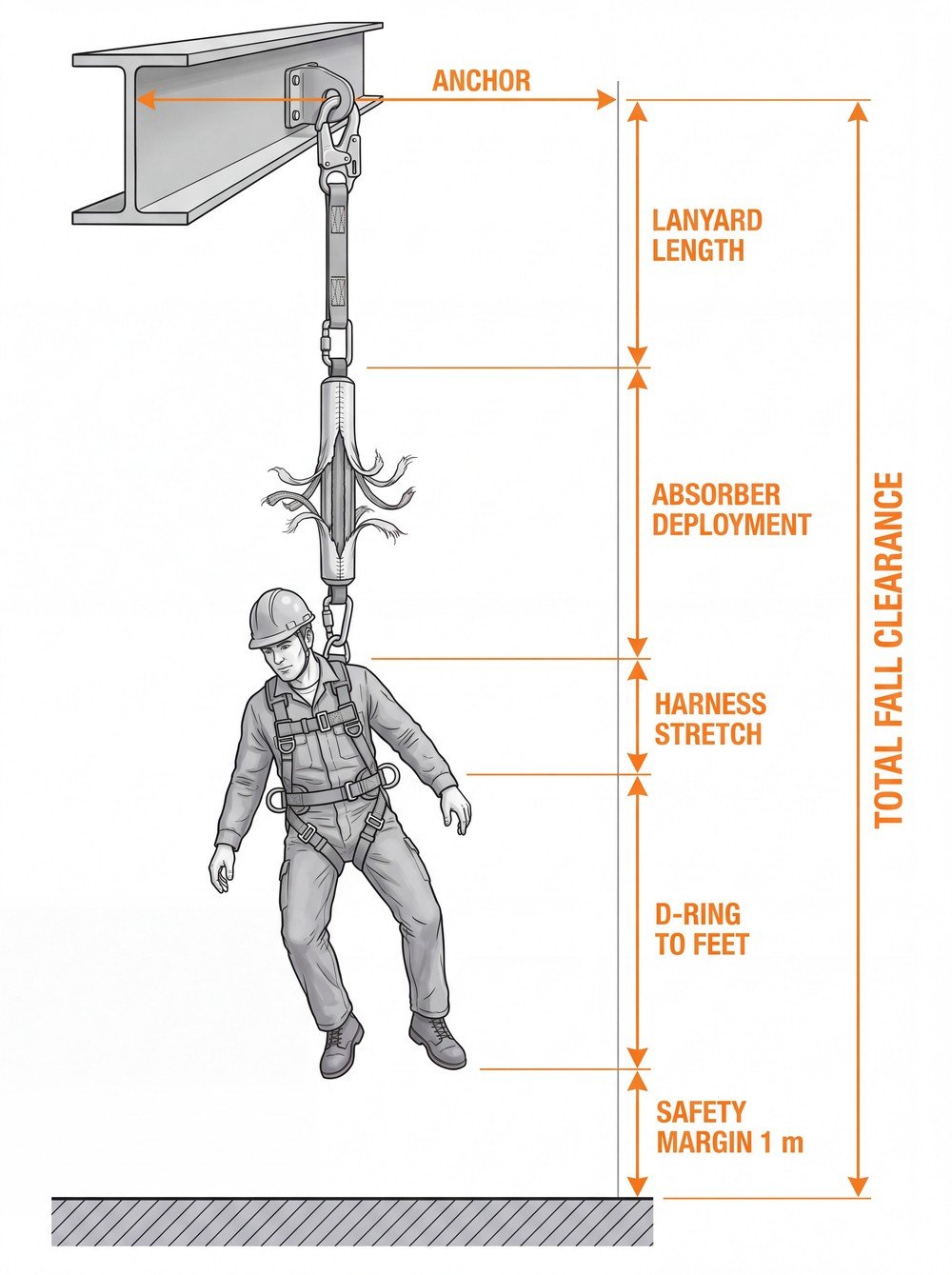
The required clearance is built up from the following elements, measured downward from the anchor point:
- the length of the lanyard assembly before deployment (up to 2 m);
- the maximum deployment of the energy absorber, as stated by the manufacturer (commonly up to about 1.75 m);
- allowance for harness stretch and dorsal D-ring displacement, per the manufacturer’s instructions (typically a few tens of centimetres);
- the distance from the dorsal attachment point to the wearer’s feet (around 1.5 m for many adults);
- a residual safety margin below the feet, commonly taken as 1 m.
Added together, a conventional 2 m energy-absorbing lanyard anchored at dorsal-ring height typically needs on the order of 6 to 7 m of clear space below the anchor. The exact figure for a given product is in its instructions for use, and that figure is the one to design to.
Where the available clearance is less than the calculated requirement, the answer is not a shorter tug on the lanyard. It is a different solution: a retractable type fall arrester to EN 360 with a verified clearance figure, a guided type fall arrester, a work restraint system that prevents the wearer reaching the edge at all, or collective protection such as edge protection or a working platform. Restraint and collective measures sit higher in the hierarchy of control that ISO 45001 expects an organisation to apply, and they remove the clearance problem rather than managing it.
Twin-leg lanyards: continuous attachment without parking the spare leg wrongly
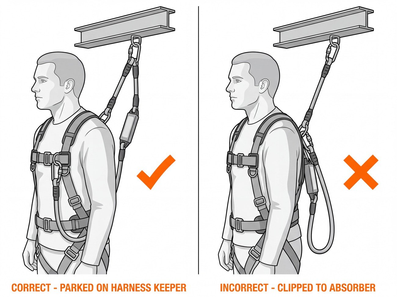
A twin-leg (Y) energy-absorbing lanyard allows continuous attachment while moving along structure: one leg stays connected while the other is transferred. Two rules govern its use.
First, both legs share a single energy absorber, and the absorber is the end that attaches to the harness. Only one leg is ever loaded in a fall; connecting both legs to two separate anchors to “double up” strength is not how the assembly is designed to work and can bypass the absorber’s function.
Second, the unused leg goes on the dedicated parking attachment provided on the harness or absorber pack – not on a structural A-marked attachment point, and not clipped back to the loaded leg. Parking elements are designed to release under load so that the free leg does not transmit force into the harness or interfere with the absorber’s deployment. Anything improvised does not have that behaviour.
Pre-use checks and periodic examination under EN 365
EN 365 sets the general requirements for instructions for use, maintenance, periodic examination, repair, marking and packaging of personal fall protection equipment. Two levels of inspection apply.
Pre-use check by the wearer, every time, before the lanyard is put into service that shift:
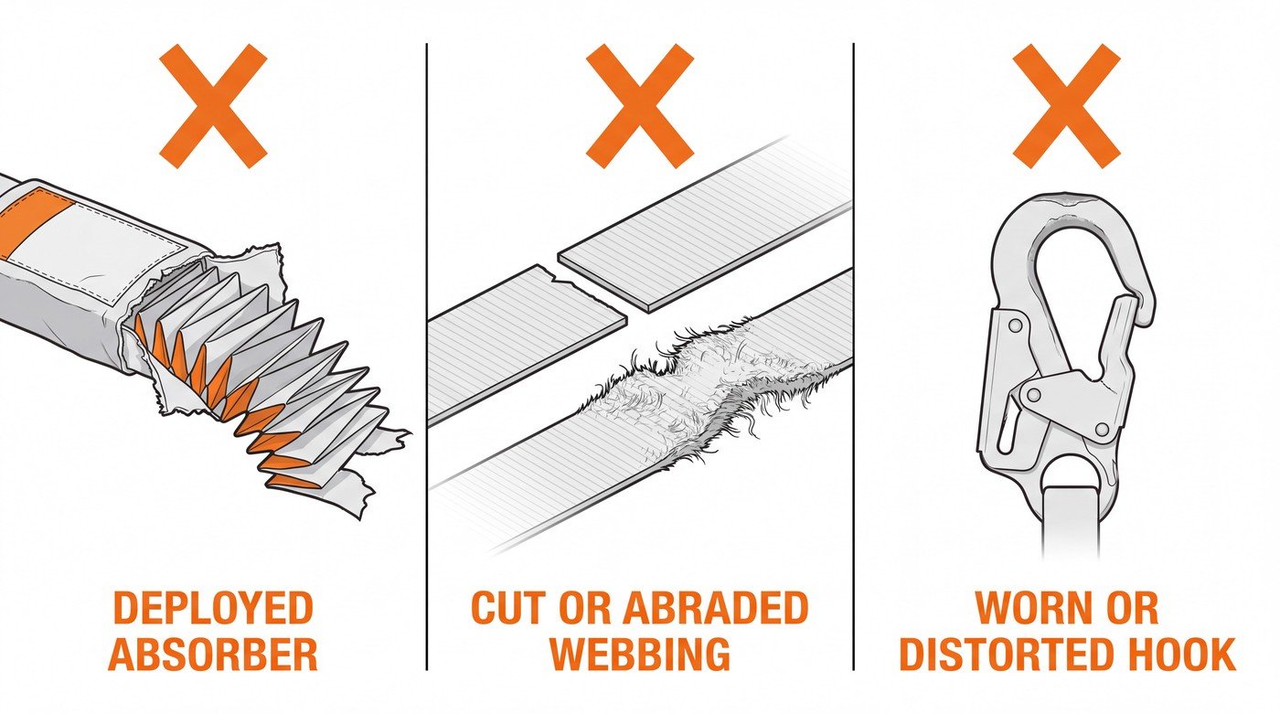
- Webbing and rope: cuts, abrasion, fraying, broken or pulled stitching, chemical staining, glazing or hardening from heat, UV degradation.
- Energy absorber pack: intact cover, no sign of deployment, tear-webbing indicator not exposed or torn, stitching sound.
- Connectors: gate closes and locks automatically or the sleeve screws fully home, no deformation, no cracks, no deep corrosion, gate and rivet free-moving, no wear grooves at the load-bearing nose.
- Markings: standard number (EN 354 / EN 355), manufacturer, serial number, year of manufacture and rated user mass legible.
- Terminations and thimbles: seated, no slipped sleeves, no exposed wire strands.
Periodic examination by a competent person: EN 365 calls for periodic examination at least every 12 months, with a documented record. Frequency should increase where use is intensive or the environment aggressive – heat, chemicals, welding spatter, abrasive dust, marine conditions – and national legislation may impose shorter intervals. The examination record should identify the item by serial number and state clearly whether it remains fit for use.
After a fall or a shock load, the lanyard is finished
An energy absorber that has deployed, even partially, has done its single job. It cannot be repacked, resewn or returned to service. The same applies to any lanyard or connector that has taken a fall load, and to a harness that has arrested a fall. Quarantine the equipment immediately with a clear tag, remove it from the store where serviceable kit is kept, and dispose of it so that it cannot be picked up again by mistake. Send it back to the manufacturer only where their instructions provide for that.
Suspension after an arrested fall is its own emergency. A fall-arrest system is only complete when there is a rescue arrangement that can reach and recover a suspended person promptly, with the equipment and trained people to do it available while the work is in progress. A plan that relies on calling the emergency services and waiting is not a rescue plan for a suspended worker.
The misuses that recur most often
- Anchoring at or below foot level with an absorber that is not approved for fall factor 2.
- Working where clearance below the anchor is less than the manufacturer’s stated requirement.
- Connecting the lanyard to a side D-ring, belt, tool loop or ventral attachment instead of an A-marked fall-arrest point.
- Knotting the lanyard to shorten it, which both reduces strength at the knot and defeats the assembly’s tested configuration.
- Wrapping the lanyard around a beam and clipping back to itself, unless the product is specifically designed and marked for choke or girth-hitch use.
- Parking the unused leg of a twin-leg lanyard on a structural harness attachment point.
- Keeping a lanyard in service after visible deployment of the absorber, or after any unrecorded shock load.
- Using scaffold hooks on structure outside their designed jaw opening, or leaving a screwgate sleeve untightened.
Practical takeaway
Before any lanyard leaves the store, three figures should already be known for the task: the required clearance from the manufacturer’s instructions, the height and rating of the anchor, and the wearer’s total kitted-out mass against the product’s rated range. If any of the three cannot be confirmed, the correct next step is to change the system – restraint, a retractable arrester with verified clearance, or collective protection – rather than proceed with a lanyard that cannot function as tested. For the next stage, review the anchor requirements in EN 795 for the anchor type actually available on your structure, and confirm your periodic examination records against the 12-month minimum in EN 365.
Frequently asked questions
Is an EN 354 lanyard on its own a fall-arrest system?
No. An EN 354 lanyard is webbing, rope or wire rope with terminations, up to a maximum length of 2 m, and on its own it is only a connecting element. Used alone in a fall it transmits essentially the full arrest force to the wearer. It becomes part of a fall-arrest system only when combined with an EN 355 energy absorber, an EN 361 full body harness and an anchor conforming to EN 795.
What force limit and length limit does EN 355 set?
Under EN 355 the arrest force must not exceed 6 kN, and the total length of the assembly — energy absorber, lanyard and connectors, including deployment — must not exceed 2 m before deployment. The absorber's stitching tears progressively, extending the stopping distance and capping the peak force at or below 6 kN.
Which harness attachment points can a fall-arrest lanyard be connected to?
Only the designated fall-arrest attachment points of an EN 361 harness, marked with a capital A. These are normally a dorsal (rear) D-ring or webbing loop between the shoulder blades, and on many models a sternal (front) attachment. Where two elements form one attachment point they are marked A/2 and both must be connected. Side D-rings (EN 358), ventral attachments on EN 813 sit harnesses, tool loops, belts and any point not marked A are not fall-arrest points.
Why should the anchor be overhead and directly above the wearer?
Anchor height determines fall distance and lateral position determines whether the wearer swings. An anchor above the dorsal attachment point keeps the fall short; anchoring at foot level with a 2 m lanyard means a free fall of roughly twice the lanyard length before the absorber begins to work — a fall factor 2 situation. Only some absorbers are tested and approved for fall factor 2, as stated in the manufacturer's instructions. Anchoring off to one side creates a pendulum, so the wearer can strike structure, plant or the edge, and the lanyard may be dragged across an unprotected edge where webbing can be cut through at loads far below its rated strength.
Does the rated user mass on the label mean body weight?
No — it is total kitted-out weight, not body weight alone. EN 355 was historically verified with a 100 kg test mass, and many current products are certified for a wider range, often up to 140 kg including tools and equipment. That figure appears on the product label and in the manufacturer's instructions, and it is the figure that governs.
Need this as a document you can issue? The template library gives you the risk assessments, permits and inspection logs in editable form — and employer plans cover a whole team with completion records.