Safety / Tips and Tricks / Rope access and confined space
Activity 01 · Rope access
Understanding and Optimising Fall Clearance
A harness to EN 361 , a certified anchor and a correctly connected energy absorber are worthless if there is not enough clear space beneath the worker for the system to do its job. Fall clearance is the number that decides whether a fall is arrested in mid-air or against a floor, a beam or a stack of materials. It is also the single figure most often left out of a method statement — and the one that changes every time an anchor is moved, a lanyard is swapped or a work platform is lowered. This article sets out how fall clearance is calculated under the EN framework, which components consume it, and what can realistically be done when there is not enough of it.
What fall clearance means in practice
Fall clearance is the minimum unobstructed vertical distance required below the user, at the moment the fall begins, for the fall arrest system to bring the fall to a stop before any part of the body strikes the ground, a lower level or an obstruction.
Two measurement datums are in common use, and mixing them up is a frequent source of error:
- Below the anchor point — the datum most manufacturers use in their instructions for use, because the anchor is the fixed reference for the whole system.
- Below the user’s feet — the datum a supervisor can actually measure on site with a tape from the working surface.
The difference between them is the distance from the dorsal attachment point to the soles of the feet, roughly 1.5 m for an average adult. Whichever datum is used, it must be stated explicitly on the drawing or in the risk assessment.
The four components that consume fall clearance
Every clearance calculation is built from the same four elements. The values below are the limits set by the relevant product standards; the actual figures for a specific device are given in its instructions for use, which are required under EN 365 and take precedence over any generic calculation.
| Component | Typical value | Source |
|---|---|---|
| Free fall distance | 0 m to 4 m | Lanyard length plus the distance the anchor sits below the dorsal attachment. EN 354 limits a lanyard assembly — including terminations, energy absorber and EN 362 connectors — to a total of 2 m. |
| Arrest (deceleration) distance | Not more than 1.75 m for an energy absorber to EN 355; not more than 2 m for a retractable type fall arrester to EN 360 | Dynamic performance requirements of the product standard; the device’s own instructions state the figure to use. |
| Harness extension and dorsal attachment slide | Approximately 0.3 m to 0.5 m | Manufacturer’s instructions. Webbing elongates and the dorsal D-ring rides upwards under load. |
| Safety margin (residual clearance) | 1 m is the value commonly specified by manufacturers | Not a standardised constant. It absorbs differences in user stature, total mass and the accuracy of the site measurement, and keeps the feet clear of the obstruction below. |
One further variable sits behind all of these: mass. EN 355 and EN 360 dynamic tests are performed with a rigid 100 kg test mass. Products are marked with a rated user mass — often between 100 kg and 140 kg — which includes clothing, tools and anything carried. A user near the upper end of that range will generally see longer deployment than the tested worst case for a 100 kg mass, and the manufacturer’s clearance figure for that mass band applies.
Worked example: a 2 m energy-absorbing lanyard to EN 355
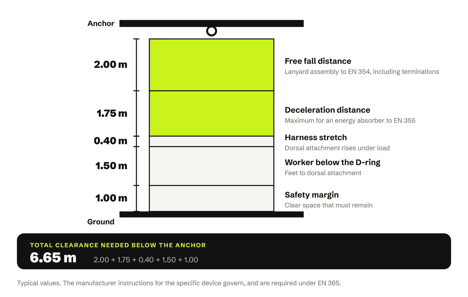
Take a worker whose dorsal attachment is level with the anchor point, using a 2 m lanyard with an integral energy absorber:
- Free fall: 2.0 m (the full lanyard length, because the anchor is at dorsal attachment height)
- Absorber deployment: 1.75 m (the EN 355 maximum, unless the instructions give a lower figure)
- Harness extension and D-ring slide: 0.4 m
- Safety margin: 1.0 m
Clearance required below the user’s feet: 5.15 m. Measured below the anchor point, add the 1.5 m from the dorsal attachment down to the feet, giving approximately 6.65 m.
This is why a 2 m absorber lanyard is unsuitable for most work at intermediate heights: on a 4 m high platform there is simply no configuration in which it can work. Note also that EN 355 dynamic testing is carried out at a 4 m free fall with a 100 kg mass. That test condition represents the worst permitted case — an anchor at foot level with a full 2 m lanyard — not a comfortable operating margin.
Anchor position is the biggest single variable
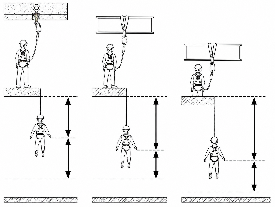
Free fall is the only component the user controls directly on site, and it is controlled almost entirely by where the anchor sits relative to the dorsal attachment point. With the same 2 m lanyard:
- Anchor overhead, 2 m above the dorsal attachment: the lanyard is already taut, free fall is close to zero, and only deployment, harness extension and the margin consume clearance.
- Anchor level with the dorsal attachment: free fall of 2 m.
- Anchor at foot level: free fall of approximately 4 m, and an arrest force at the upper limit of what the absorber is designed to control.
Every metre the anchor is lowered relative to the dorsal D-ring adds a metre of free fall, and each metre of free fall adds a metre of required clearance before deployment even begins. Raising the anchor is almost always the cheapest optimisation available.
Retractable type fall arresters and guided type fall arresters
Where clearance is limited, the practical answer is usually a device that reduces free fall rather than a longer margin below.
Retractable type fall arresters (EN 360)
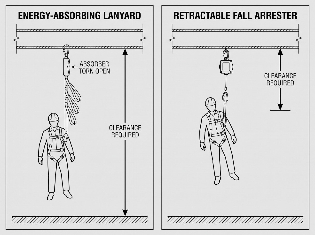
A retractable device pays out and retracts to keep the line short, so free fall is limited to the small amount of travel before the brake engages. EN 360 caps the arrest distance at 2 m, and many devices achieve considerably less. Required clearances for overhead installation are typically in the region of 2 m to 4.5 m below the feet, but the figure to use is the one marked on the device or given in its instructions — not a rule of thumb.
Two conditions attach to that short clearance. First, it assumes the device is anchored overhead. Second, most EN 360 devices are tested for vertical use only; use over an edge or in a horizontal or inclined application requires a device specifically tested for it, in line with the CEN interpretation sheet CNB/P/11.060, and that configuration comes with its own, larger clearance figure.
Guided type fall arresters (EN 353-1 and EN 353-2)
On ladders, towers and mast climbs, a guided type fall arrester on a rigid anchor line (EN 353-1) gives the shortest arrest distance because the rail does not stretch. A guided type fall arrester on a flexible anchor line (EN 353-2) must additionally account for rope elongation and any slippage of the device along the line, so the required clearance is larger and depends on line length and tension. Both are stated in the system documentation.
Swing falls: the clearance you did not measure
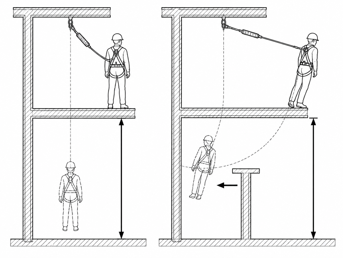
Clearance calculations assume a vertical fall directly beneath the anchor. Once the user works to one side of the anchor, the fall becomes a pendulum, and two things change.
The lowest point of the swing is below the vertical drop. If the dorsal attachment starts 2 m below an overhead anchor with a 3 m lateral offset, the loaded line length is about 3.6 m. At the bottom of the arc, the user hangs 3.6 m below the anchor — approximately 1.6 m lower than the same fall taken directly beneath it, before any deployment is added.
The swing path itself needs clearance. The user travels sideways through the arc at speed, and structural steel, scaffolding, plant and edges along that path are impact hazards that no clearance figure below the feet will address.
Manufacturers commonly limit lateral deviation from the vertical to around 30° for this reason, and specify a separate, larger clearance where working outside that cone is unavoidable. Moving the anchor so the work is directly beneath it, or using a horizontal anchor line that follows the work, removes the problem at source.
Flexible horizontal anchor lines and system sag
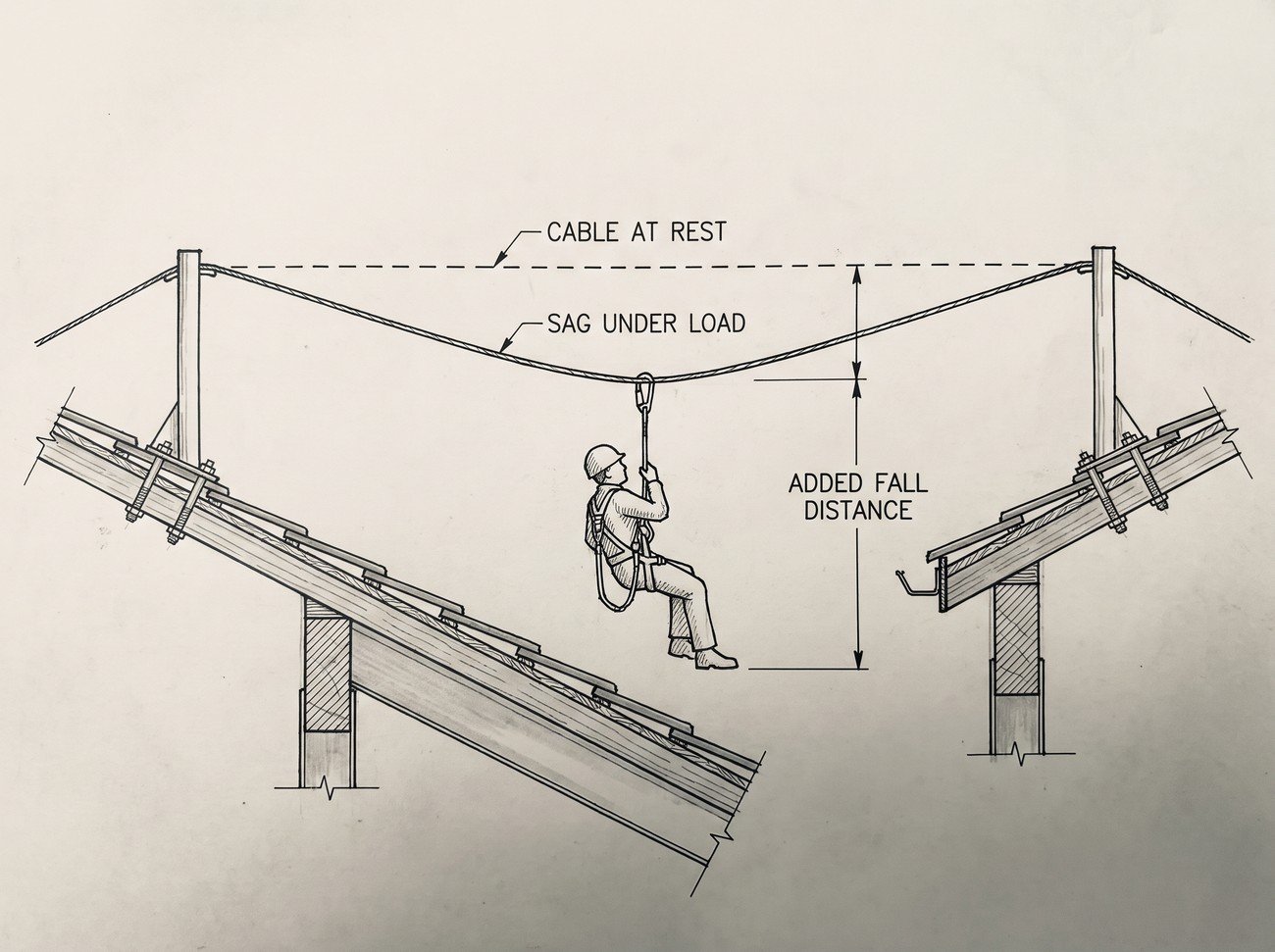
A horizontal flexible anchor line — a Type C anchor device under EN 795:2012 — deflects under load, and that deflection adds directly to the fall distance. On a long span, sag can add several metres to the clearance requirement, which is why Type C systems must be supplied with clearance tables or design documentation stating the required clearance for each span, pretension and number of simultaneous users. A generic lanyard calculation performed without those tables will understate the requirement.
Note also that within EN 795:2012, Types B and E are treated as personal protective equipment under Regulation (EU) 2016/425, while Types A, C and D are permanently installed anchor devices that form part of the structure. That distinction affects who is responsible for the design documentation containing the clearance data, and it should be resolved before the system is used, not after a fall.
When the clearance is not there
If the available clearance is less than the system requires, the system is not suitable and no amount of training or supervision changes that. The practical hierarchy is:
- Eliminate the fall. Collective protection — temporary edge protection to EN 13374, permanent guardrails, or covered openings — removes the clearance question entirely.
- Use work restraint. A fixed-length lanyard adjusted so the user cannot reach the fall edge means there is no fall to arrest and no clearance requirement. Restraint must be verifiable by measurement, not by intention.
- Reduce the fall distance. Raise the anchor overhead, replace a 2 m absorber lanyard with an EN 360 retractable device, or install a rigid rail system.
- Catch the fall collectively. Safety nets to EN 1263-1, installed to EN 1263-2, arrest a fall in a much shorter distance than a personal system — though nets have their own clearance requirement below the net.
Verifying fall clearance on site
The calculation belongs in the risk assessment and method statement for the task; the verification belongs on the working surface, before work starts.
- Measure from the working surface at the point where a fall could occur — not from the nearest convenient edge, and not from a drawing that may predate the current site layout.
- Identify what is actually in the fall path. Scaffold tubes, pipework, formwork, plant and stockpiled material all reduce usable clearance, and striking them is a fall arrest failure even if the ground is far below.
- Read the marking and instructions for the specific device in use. Two absorber lanyards from different manufacturers can carry different clearance figures, and the rated user mass band matters.
- Recalculate whenever the anchor position, lanyard type, working level or user mass band changes.
- Check the equipment is within its periodic examination interval — EN 365 requires periodic examination by a competent person at least every 12 months, more frequently where conditions of use demand it.
- Confirm the rescue arrangements. Arresting a fall leaves the user suspended, and suspension is time-critical. A documented rescue plan with the means to carry it out — for example rescue lifting equipment to EN 1496 or a descender device to EN 341 — is part of the emergency preparedness and response required under ISO 45001 clause 8.2.
Takeaway
Fall clearance is a calculation with four inputs: free fall, arrest distance, harness extension and safety margin. Free fall is the input that varies most and is the one most easily reduced, by anchoring overhead or by using a retractable device instead of a 2 m absorber lanyard. Swing falls and horizontal line sag are the two factors most often omitted, and both increase the requirement rather than reduce it. Before the next work-at-height task, take the instructions for use for each fall arrest device on site, record the stated clearance figure and the datum it is measured from, and compare it against a tape measure reading taken at the actual work position.
Frequently asked questions
What is fall clearance?
Fall clearance is the minimum unobstructed vertical distance required below the user, at the moment the fall begins, for the fall arrest system to bring the fall to a stop before any part of the body strikes the ground, a lower level or an obstruction.
Which two measurement datums are used, and why does mixing them up matter?
Clearance can be measured below the anchor point — the datum most manufacturers use in their instructions for use, because the anchor is the fixed reference for the whole system — or below the user's feet, which is what a supervisor can measure on site with a tape from the working surface. The difference between them is the distance from the dorsal attachment point to the soles of the feet, roughly 1.5 m for an average adult, so the datum used must be stated explicitly on the drawing or in the risk assessment.
What are the four components of a fall clearance calculation?
Free fall distance (0 m to 4 m, from lanyard length plus how far the anchor sits below the dorsal attachment); arrest or deceleration distance (not more than 1.75 m for an energy absorber to EN 355, not more than 2 m for a retractable type fall arrester to EN 360); harness extension and dorsal attachment slide (approximately 0.3 m to 0.5 m); and a safety margin, commonly specified by manufacturers as 1 m. The actual figures for a specific device are given in its instructions for use, required under EN 365, which take precedence over any generic calculation.
How much clearance does a 2 m energy-absorbing lanyard need?
For a worker whose dorsal attachment is level with the anchor: free fall 2.0 m, absorber deployment 1.75 m (the EN 355 maximum unless the instructions give a lower figure), harness extension and D-ring slide 0.4 m, and a 1.0 m safety margin — 5.15 m below the user's feet. Measured below the anchor point, adding the 1.5 m from the dorsal attachment down to the feet gives approximately 6.65 m. This is why a 2 m absorber lanyard is unsuitable for most work at intermediate heights: on a 4 m high platform there is no configuration in which it can work.
Why is anchor position the biggest single variable?
Free fall is the only component the user controls directly on site, and it is controlled almost entirely by where the anchor sits relative to the dorsal attachment point. With the same 2 m lanyard, an anchor 2 m overhead leaves the lanyard taut with free fall close to zero; an anchor level with the dorsal attachment gives 2 m of free fall; and an anchor at foot level gives approximately 4 m of free fall with an arrest force at the upper limit of what the absorber is designed to control. Every metre the anchor is lowered adds a metre of free fall and a metre of required clearance, so raising the anchor is almost always the cheapest optimisation available.
Need this as a document you can issue? The template library gives you the risk assessments, permits and inspection logs in editable form — and employer plans cover a whole team with completion records.