Safety / Tips and Tricks / Rope access and confined space
Activity 01 · Rope access
Energy Absorber Clearance: How to Calculate Required Fall Clearance for I and Y Lanyards
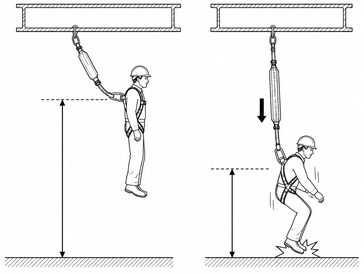
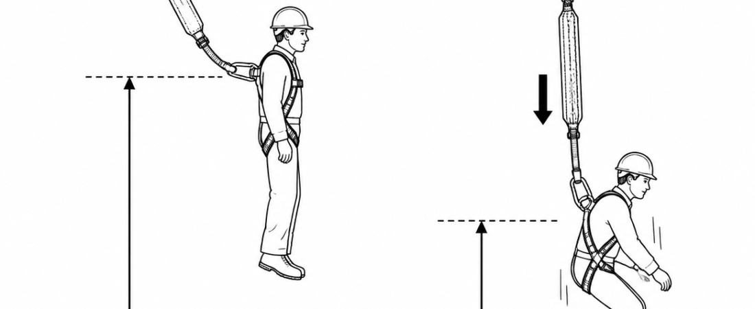
An energy-absorbing lanyard only works if there is enough empty space below the user for it to do its job. If the required clearance is not available, the absorber will not have deployed fully before the falling worker reaches the ground, a lower level, or an obstruction — and the arrest force the absorber was chosen to limit never gets limited. Clearance is therefore not a paperwork detail: it is the deciding factor in whether an EN 355 absorber is the right piece of equipment for a given work position, or whether a retractable type fall arrester (EN 360) or a fall restraint arrangement should be used instead.
This article sets out how energy absorber clearance is built up component by component, how the figure changes with anchor height, and where single-leg (“I”) and twin-leg (“Y”) absorbers behave differently. Throughout, the governing number is the one printed in the manufacturer’s instructions for the specific product — EN 355 sets performance requirements for the absorber, not a universal clearance value.
What EN 355 actually fixes, and what it leaves to the manufacturer
EN 355 covers energy absorbers as a component of a personal fall protection system defined by EN 363. Two of its requirements matter directly to clearance:
- Maximum arrest force of 6 kN. This is the force the absorber must not exceed when tested with a rigid 100 kg mass.
- Maximum total length of 2 m. The 2 m limit applies to the whole assembly — absorber, lanyard, terminations and connectors together — not to the webbing alone.
The dynamic performance test is carried out at fall factor 2, i.e. with the anchor at the level of the attachment point of the test mass, so an EN 355 absorbing lanyard is designed and tested for the worst-case anchor position as well as for overhead anchors.
What EN 355 does not do is tell a supervisor how much air is needed under the work platform. The deployment (tear-out) length of the absorber, the required clearance, and the permitted user mass range are declared by the manufacturer in the instructions for use, which EN 365 requires to be supplied with, and kept for, the equipment. Deployment values of up to 1.75 m are typical for a 2 m absorbing lanyard, but the figure varies by product, by construction and by the certified mass range — read it, do not assume it.
The four components of energy absorber clearance
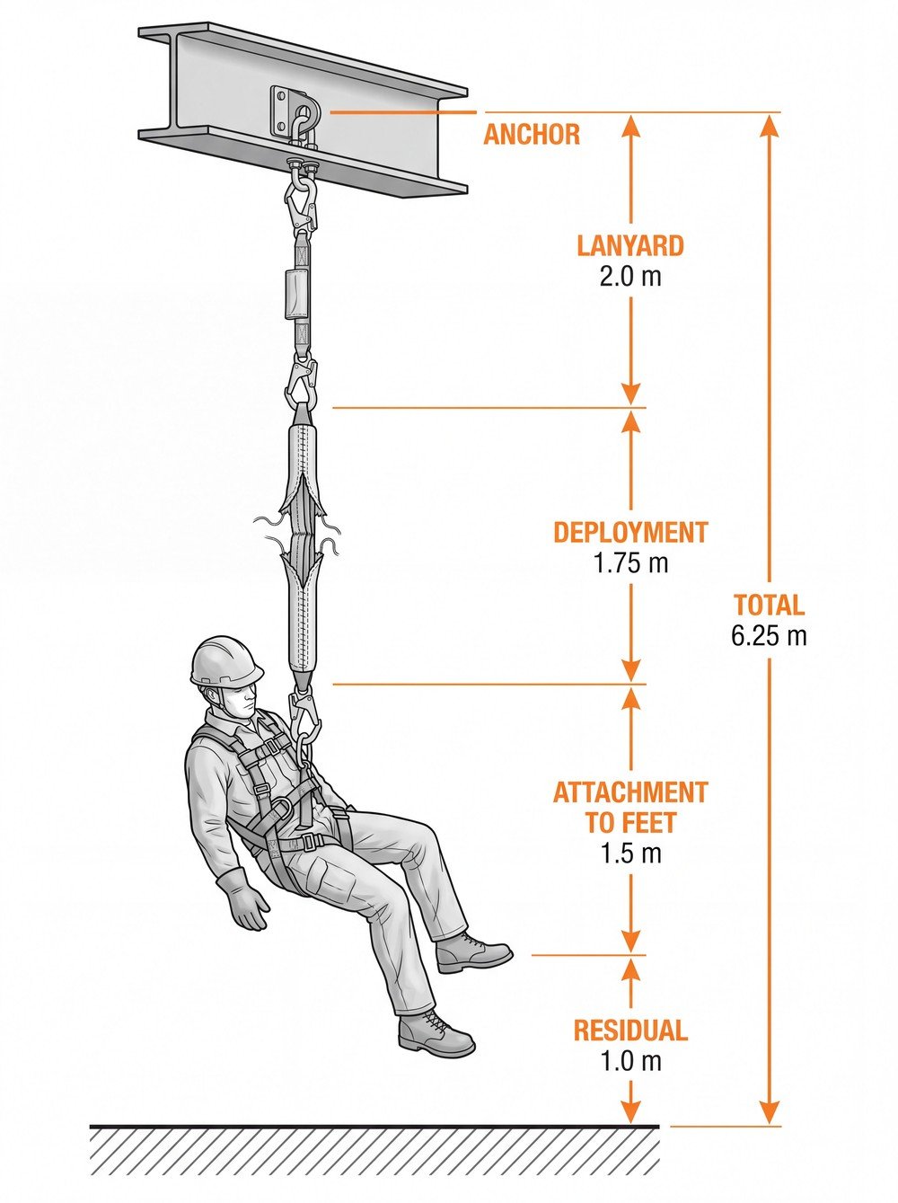
Required clearance for an I or Y absorbing lanyard is measured downwards from the anchor point and is made up of four parts:
- Length of the lanyard assembly (L) — up to 2.0 m for an EN 355 product, including the connectors at both ends.
- Deployment of the absorber (D) — the tear-out length declared by the manufacturer; commonly up to 1.75 m for a 2 m absorber.
- Distance from the dorsal or sternal attachment to the soles of the feet (H) — approximately 1.5 m for an average adult, plus any harness and attachment displacement that the manufacturer has not already included.
- Residual clearance below the feet (C) — an additional safety margin, usually stated as 1.0 m in manufacturers’ instructions, so that the arrested user comes to rest clear of the surface below.
For a worst-case 2 m absorbing lanyard: 2.0 + 1.75 + 1.5 + 1.0 = 6.25 m below the anchor point. Products with shorter lanyards, lower declared deployment, or a compact absorber pack will give smaller figures; some manufacturers publish separate values for overhead anchors and for foot-level anchors, and those published values take precedence over generic arithmetic.
Why anchor height changes the number that matters on site
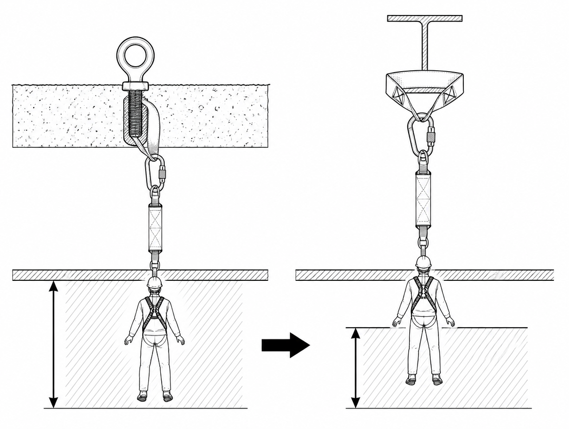
The 6.25 m in the example is measured from the anchor. The figure a supervisor has to check against the structure is different: it is the clear distance below the working surface. Raising the anchor converts part of the required clearance into height above the platform, so the same lanyard needs less space underneath.
| Anchor position relative to the working surface | Fall factor (2 m lanyard) | Clear space needed below the working surface |
|---|---|---|
| At surface level (feet) | 2 | 6.25 m |
| 1.0 m above the surface | 1.5 | 5.25 m |
| Approx. 1.5 m above the surface (dorsal attachment level) | 1 | 4.75 m |
| 2.5 m above the surface (overhead) | Approx. 0.5 | 3.75 m |
These figures are deliberately conservative: they hold the deployment at its maximum even where a lower fall factor would produce less tear-out. They are valid only where the anchor is more or less vertically above the work position. They also assume the absorber is certified for a foot-level anchor at fall factor 2 — which EN 355 products are, but combinations that include an added connector, an extension lanyard or a horizontal lifeline are not automatically.
Two site conditions erode clearance and are not in the arithmetic above:
- Swing fall. Where the anchor is offset horizontally, the user swings on arrest. This both increases the drop below the anchor and creates a risk of striking structure to the side. Keeping the anchor as close to vertically overhead as the work allows is the practical control.
- System deflection. A horizontal flexible anchor line (EN 795 Class C) sags under load, and a rail system has its own deflection value. The sag stated in that system’s installation and use documentation is added to the clearance figure. Anchor devices should be selected and installed under EN 795 to the type appropriate to the structure.
Single-leg (I) absorbers: the straightforward case
An I-type absorbing lanyard has one absorber and one connector at the anchor end. Clearance is the four-component sum above, using the declared values for that product. Two points cause most of the errors seen in practice:
- Do not extend the assembly. Adding a karabiner, a sling or a second lanyard to reach an awkward anchor pushes the assembly past the 2 m limit of EN 355 and invalidates the manufacturer’s clearance figure. A large scaffold hook already accounts for a substantial part of the 2 m; the length declared by the manufacturer includes it.
- Do not stack energy absorbers. An EN 355 absorbing lanyard connected in series with a retractable type fall arrester (EN 360) or a guided type fall arrester (EN 353-2) produces a total deployment neither product was tested for, and a clearance requirement nobody has calculated. Each fall arrest sub-system carries its own clearance value and is used as supplied.
Twin-leg (Y) absorbers: two constructions with different clearance behaviour
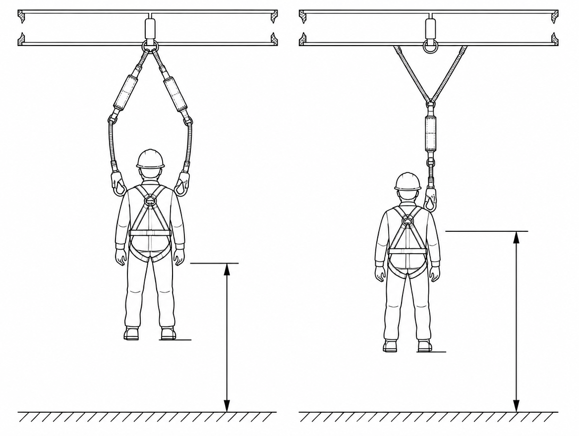
“Y” lanyards exist in two distinct constructions, and the difference matters when the clearance figure is worked out:
One shared absorber at the harness end
The absorber sits between the harness attachment and the fork; the two legs run from the fork to their connectors. Only one absorber can deploy, so the deployment term in the calculation is counted once. The relevant length for clearance is the harness attachment to the end of the connector on one leg — not the sum of both legs.
An absorber in each leg
Each leg carries its own absorber pack. Where only one leg is connected to an anchor at the moment of the fall, clearance is based on the deployment of that single leg. Where both legs are connected to anchors during a transfer, load sharing is unpredictable and both absorbers can be partially involved; some manufacturers permit this, others prohibit connecting the two legs to two separate anchors. The instructions for the specific product decide, and the transfer sequence should be planned around whichever behaviour is stated.
The parked leg: the most common clearance error on Y systems
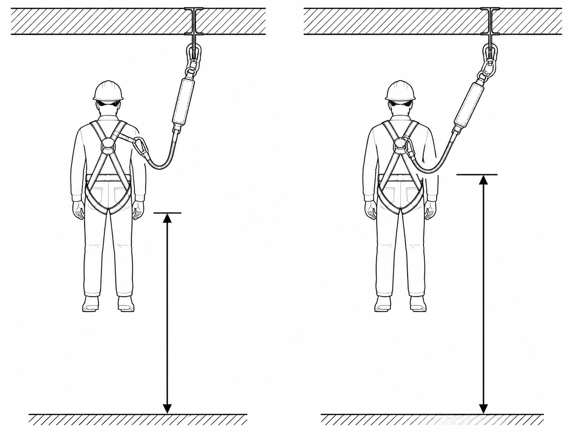
While the user moves along a structure with one leg connected, the free leg has to go somewhere. It belongs on the harness’s dedicated lanyard parking element, which is intended to hold the connector and to release or detach without transmitting arrest force into the harness structure.
Clipping the free leg to a fall arrest attachment point (the dorsal or sternal D-ring of an EN 361 harness), to a work positioning ring (EN 358), or to load-bearing harness webbing changes the geometry of the system in two ways:
- The parked leg becomes part of the load path. Its absorber can be triggered along with the loaded one, or the leg can pay out, adding up to the full leg length to the fall distance — a clearance requirement well beyond the value on the product label.
- Arrest force can be applied to a harness element that was never tested for it, and to the user’s body in an unintended direction.
Where a harness has no parking element, or where the connectors are too large for it, that is an equipment selection problem to be resolved before the work starts — not something to improvise at height.
User mass, tools and the mass range on the label
The EN 355 dynamic performance test uses a 100 kg mass. Many absorbers on the EU market are additionally certified over a wider range — commonly stated as something like 50–140 kg including clothing, tools and equipment — and those products often publish more than one clearance value, because a heavier combined mass produces greater tear-out.
The figures that need to be read off the marking and the instructions before a clearance decision is made are:
- The standard the absorber conforms to (EN 355) and the notified body number on the CE marking.
- The permitted total mass range of the user including equipment.
- The maximum deployment and/or the minimum required clearance, and whether that value assumes an overhead or foot-level anchor.
- Total assembly length as supplied.
Checking clearance against the actual structure
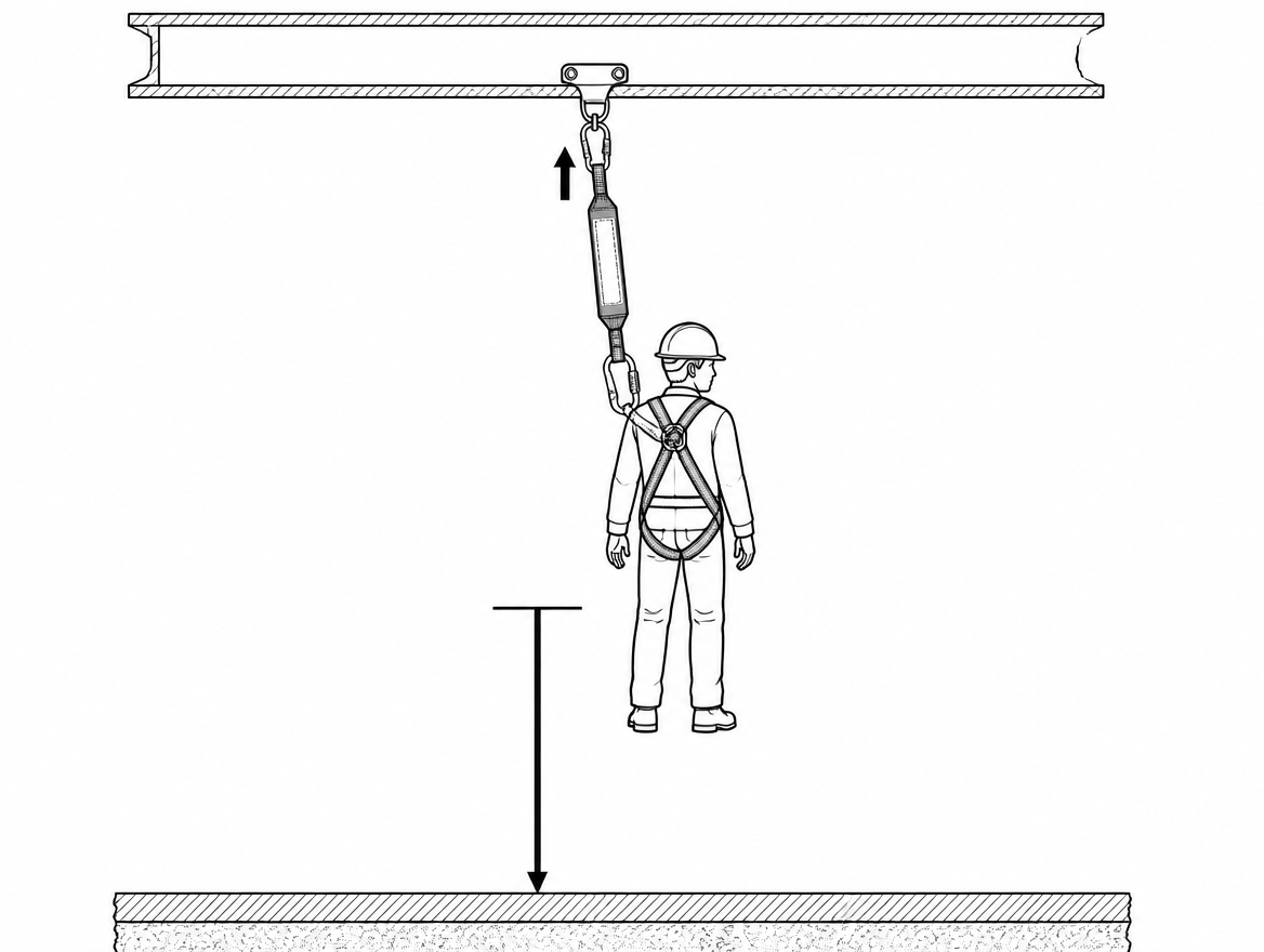
A clearance value is only useful when it has been compared with what is genuinely below the work position. The clear zone has to be free of obstructions over the whole area the user could reach, including any swing.
- Measure from the working surface down to the first thing that would be struck — not to the ground. Steelwork, pipe racks, plant, formwork, stacked material, scaffold lifts and vehicles all shorten the available distance.
- Account for the work moving. A clearance that is adequate at one end of a beam may not be adequate at the other, or once a deck below has been installed.
- Record the figure. Writing the required clearance and the assumed anchor height into the method statement and the rescue plan means the number is available to the people who make the decision at the point of use.
Where the available clearance is less than the value the absorber requires, the absorber is the wrong choice for that position. The alternatives, in the order they are usually considered, are: restrain the user so a fall cannot occur (a fixed-length lanyard under EN 358 or an adjustable restraint arrangement, with the length set so the fall hazard cannot be reached); use a retractable type fall arrester conforming to EN 360, selected specifically for its short arrest distance and, where relevant, certified for the anchor position and edge type in use; or change the access method so that fall arrest is not required.
After a fall: a deployed absorber is finished
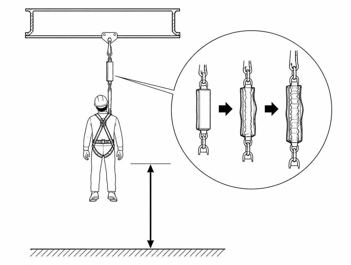
Tear-stitch and rip-panel absorbers carry a visible indicator — an inspection window, a tear tag or an exposed section of webbing — that shows whether the pack has been loaded. Any absorber that has arrested a fall, or that shows partial deployment, is withdrawn from service and destroyed or returned to the manufacturer, because its remaining deployment length and arrest force are unknown.
Under EN 365 the equipment is subject to pre-use checks by the user and to periodic examination by a competent person at intervals of at most 12 months, or more frequently where the manufacturer’s instructions or the conditions of use require it. The examination record identifies the item, the date, the findings and the next due date.
Takeaway
For an EN 355 absorbing lanyard, treat 2.0 m of assembly length, the manufacturer’s declared deployment, roughly 1.5 m of user height below the attachment and 1.0 m of residual clearance as the four terms of the sum, measure the result downwards from the anchor, and then subtract the height of the anchor above the working surface to get the space actually needed underneath. For Y lanyards, add two checks: whether the product has one shared absorber or one per leg, and whether the free leg is parked on the harness’s dedicated parking element rather than on a fall arrest or work positioning attachment point.
The next document to consult is the instructions for use supplied with the specific absorber and harness in service, alongside the anchor device documentation required under EN 795 — those three sets of figures, read together, give the clearance value that applies to the job in front of you.
Frequently asked questions
What does EN 355 actually fix, and what does it leave to the manufacturer?
EN 355 sets a maximum arrest force of 6 kN when tested with a rigid 100 kg mass, and a maximum total length of 2 m for the whole assembly — absorber, lanyard, terminations and connectors together, not the webbing alone. It does not state a universal clearance value. The deployment (tear-out) length, the required clearance and the permitted user mass range are declared by the manufacturer in the instructions for use, which EN 365 requires to be supplied with and kept for the equipment.
What are the four components of energy absorber clearance?
Measured downwards from the anchor point: the length of the lanyard assembly (up to 2.0 m for an EN 355 product, including connectors at both ends); the declared deployment of the absorber (commonly up to 1.75 m for a 2 m absorber); the distance from the dorsal or sternal attachment to the soles of the feet (approximately 1.5 m for an average adult, plus any harness and attachment displacement not already included); and a residual clearance below the feet, usually stated as 1.0 m.
How much clearance does a worst-case 2 m absorbing lanyard need?
2.0 + 1.75 + 1.5 + 1.0 = 6.25 m below the anchor point. Products with shorter lanyards, lower declared deployment or a compact absorber pack give smaller figures, and where manufacturers publish separate values for overhead and foot-level anchors, those published values take precedence over generic arithmetic.
How does raising the anchor change the clearance needed below the working surface?
Raising the anchor converts part of the required clearance into height above the platform, so the same lanyard needs less space underneath. With a 2 m lanyard: an anchor at surface level (fall factor 2) needs 6.25 m below the working surface; 1.0 m above the surface (fall factor 1.5) needs 5.25 m; approximately 1.5 m above the surface at dorsal attachment level (fall factor 1) needs 4.75 m; and 2.5 m above the surface, overhead (approximately fall factor 0.5), needs 3.75 m. These figures are conservative, hold deployment at its maximum, and are valid only where the anchor is more or less vertically above the work position.
Which site conditions erode clearance beyond the basic arithmetic?
Two. Swing fall: where the anchor is offset horizontally the user swings on arrest, which both increases the drop below the anchor and creates a risk of striking structure to the side — keeping the anchor as close to vertically overhead as the work allows is the practical control. System deflection: a horizontal flexible anchor line (EN 795 Class C) sags under load and a rail system has its own deflection value; the sag stated in that system's installation and use documentation is added to the clearance figure.
Need this as a document you can issue? The template library gives you the risk assessments, permits and inspection logs in editable form — and employer plans cover a whole team with completion records.