Safety / Tips and Tricks / Rope access and confined space
Activity 01 · Rope access
Oblique Anchors and Fall Distance: How Lateral Offset Changes the Clearance Calculation
Most fall clearance calculations assume something that is often untrue on site: that the anchor point sits directly above the person attached to it. When the anchor is offset to one side — an oblique anchor — the arrest geometry changes, the lowest point of the fall moves away from the worker's feet, and the clear space needed below the work position stops being a simple vertical line. A system that has adequate clearance with the anchor overhead can bottom out, or swing the faller into a structure at road-traffic speed, with nothing changed except a few metres of lateral offset.
This article sets out the geometry, the arithmetic, and the equipment limits that apply when an anchor cannot be placed overhead, using the EN 363 system framework and the component standards that govern each part of it.
What “oblique” means in arrest geometry
An anchor is oblique when a straight line from the anchor to the attachment point on the harness — normally the dorsal or sternal fall arrest attachment of an EN 361 full body harness — deviates from vertical. Two separate quantities matter:
- The deviation angle between the connecting subsystem and the vertical, which determines whether the equipment is still being used inside its tested configuration.
- The horizontal offset between the anchor and the point where the person leaves the working level, which determines how much additional vertical drop the pendulum produces.
These are not interchangeable. A retractable type fall arrester to EN 360 mounted 2 m to one side of a worker 20 m up is at a small deviation angle but still has a 2 m offset; the same 2 m offset with the device mounted at deck level next to the worker’s feet is a much more severe case, because the free fall increases as well.
Three ways an offset anchor consumes clearance
1. Longer free fall when the anchor is not above the attachment point
Free fall is the distance travelled before the connecting subsystem begins to arrest. With an anchor above the dorsal D-ring, free fall is limited to the slack in the system. With an anchor at foot level, the attachment point must first fall past the anchor before the lanyard can come taut, so free fall approaches the length of the connecting subsystem plus the vertical distance from the anchor up to the D-ring. An energy absorber to EN 355 is qualified to keep arrest force at or below 6 kN under its specified test conditions; feeding it a longer free fall than the manufacturer’s stated maximum takes the system outside those conditions.
2. The pendulum drop after arrest
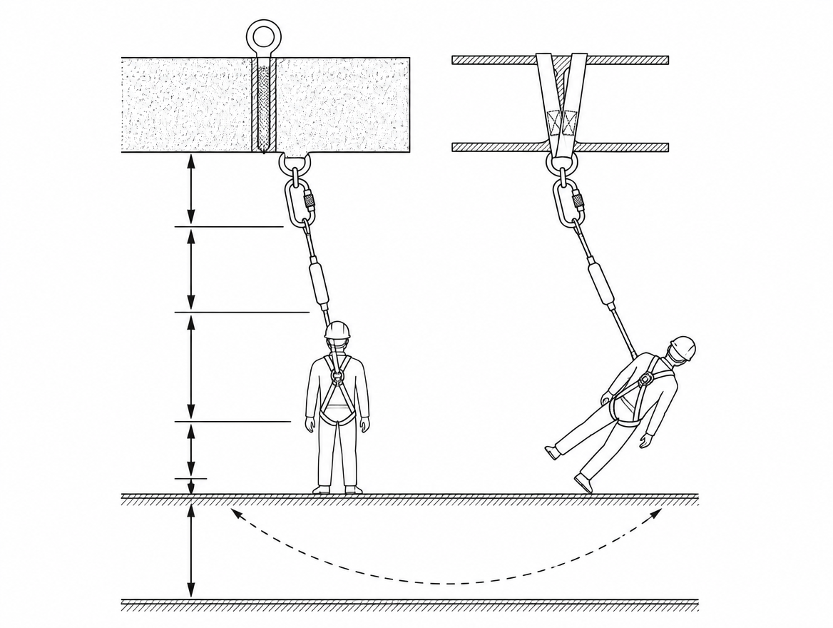
Once the system has arrested the fall, the person hangs on a radius R measured from the anchor to the harness attachment point — the connecting subsystem plus any absorber deployment plus harness stretch and D-ring slide. The lowest point of that arc is not where the arrest occurred; it is directly below the anchor. If the horizontal offset at arrest is a, the additional vertical drop as the body swings to the plumb line is:
extra drop = R − √(R² − a²)
The relationship is strongly non-linear. For an arrest radius of 4.00 m:
| Horizontal offset a | Offset as fraction of R | Extra vertical drop | Horizontal speed at bottom of swing |
|---|---|---|---|
| 1.0 m | 0.25 | 0.13 m | ≈ 1.6 m/s |
| 2.0 m | 0.50 | 0.54 m | ≈ 3.2 m/s |
| 3.0 m | 0.75 | 1.35 m | ≈ 5.2 m/s |
| 3.5 m | 0.88 | 2.06 m | ≈ 6.4 m/s |
The speeds are derived from the extra drop by free-fall energy conversion (v = √(2gh)); 6.4 m/s is roughly 23 km/h of horizontal travel into whatever occupies the swing path. The first metre or two of offset costs very little clearance. Beyond about half the arrest radius, the cost rises sharply.
3. Obstructions inside the swept arc
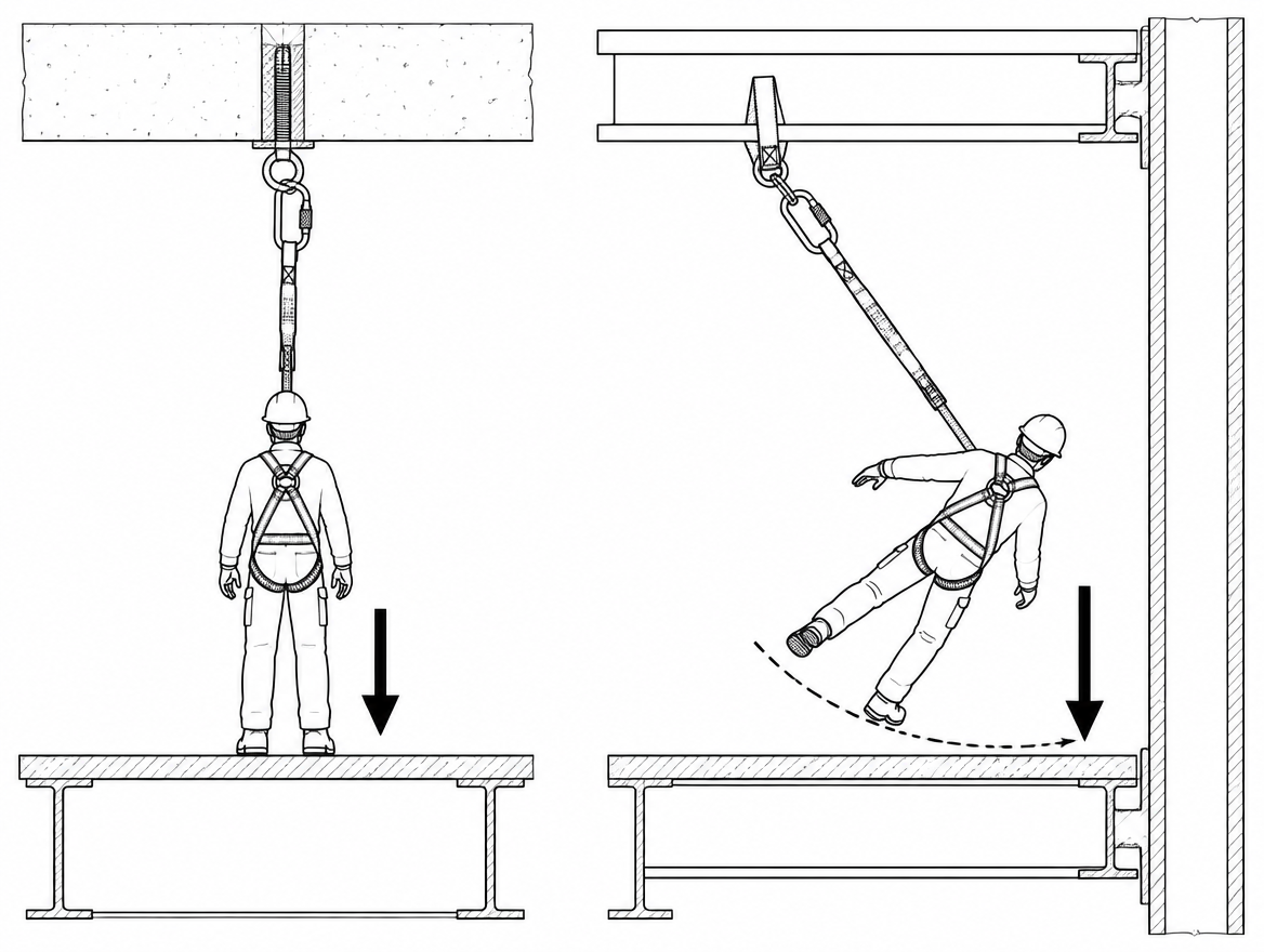
Even where the vertical clearance below the anchor is sufficient, the volume swept by the body between the arrest point and the plumb line has to be clear. Scaffold standards, formwork, stacked material, plant, tank walls and structural steel are the usual occupants of that volume. Impact against a structure during a swing fall is not attenuated by the energy absorber, which only controls forces along the axis of the connecting subsystem.
Working the clearance from the anchor, not from the worker
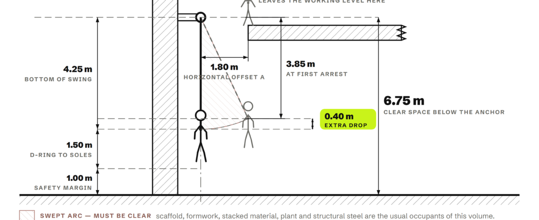
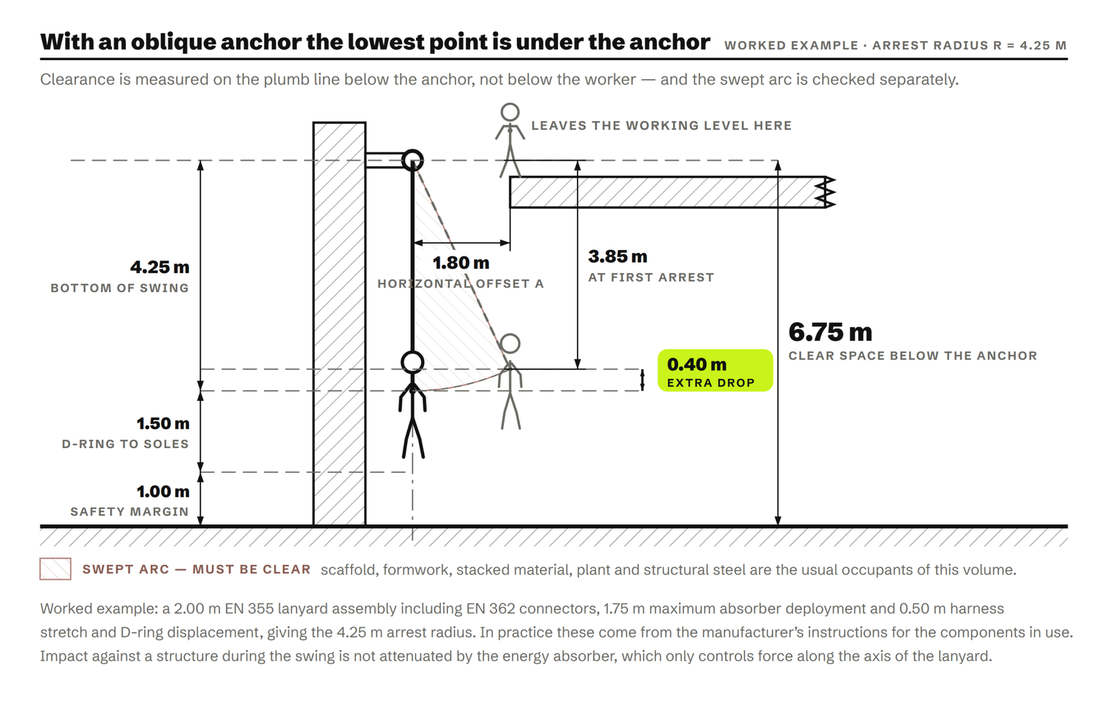
The practical rule that follows from the geometry: with an oblique anchor, required clearance is measured on the plumb line below the anchor, and the swept arc is checked separately. A worked example for an energy-absorbing lanyard system, using figures that must in practice come from the manufacturer’s instructions for the specific components:
- EN 355 energy-absorbing lanyard assembly, nominal length including EN 362 connectors: 2.00 m
- Maximum absorber deployment stated by the manufacturer: 1.75 m
- Harness stretch and dorsal D-ring displacement: 0.50 m
- Arrest radius R from anchor to D-ring after arrest: 4.25 m
- Horizontal offset at the moment the person leaves the working level: 1.80 m
- Depth of the D-ring at first arrest: √(4.25² − 1.80²) = 3.85 m below the anchor
- Depth at the bottom of the swing: 4.25 m below the anchor
- Dorsal D-ring to the soles of the feet: 1.50 m
- Safety margin: 1.00 m
- Clear space required below the anchor: 6.75 m, with the full arc between 1.80 m offset and the plumb line free of obstruction.
Two checks are needed, not one. The vertical check is made below the anchor. The lateral check is made across the arc. Where the calculation is close, the offset — not the equipment — is usually the cheapest variable to change.
Equipment limits that oblique use can breach
Component standards define the configurations in which the performance figures were obtained. Oblique use frequently sits outside them.
- EN 360 retractable type fall arresters. Devices are type-tested in a defined orientation. Manufacturers commonly state a maximum permitted deviation from vertical — the figure is device-specific and appears in the instructions for use; a generic angle should not be assumed. Where the line can bear on an edge, only devices qualified for that use are appropriate; the notified bodies’ Recommendation for Use sheets on edge and horizontal/inclined applications of retractable devices are the reference for that additional testing, and a device without it is not made suitable by a risk assessment.
- EN 353-2 guided type fall arresters on a flexible anchor line. These depend on the anchor line orientation for the arrester to engage correctly. Working laterally away from the line, or letting the line take an oblique path, is outside the intended use.
- EN 795 anchor devices. Types A, B, C, D and E are qualified against defined loading directions. A Type B transportable device or a Type A structural anchor loaded at an angle it was not tested for may see a load component the fixing was never assessed against — a critical point for through-bolts, beam clamps and parapet clamps. Type E deadweight anchors rely on friction and are qualified only up to a stated maximum surface inclination; an oblique pull generates a lateral force component that is exactly the load case they resist least well. Where more than one person may be attached, the multi-user requirements of CEN/TS 16415 apply.
- EN 358 work positioning and restraint belts are not fall arrest equipment. They must not be substituted into a system where an oblique fall is possible.
Edges, friction and absorber behaviour
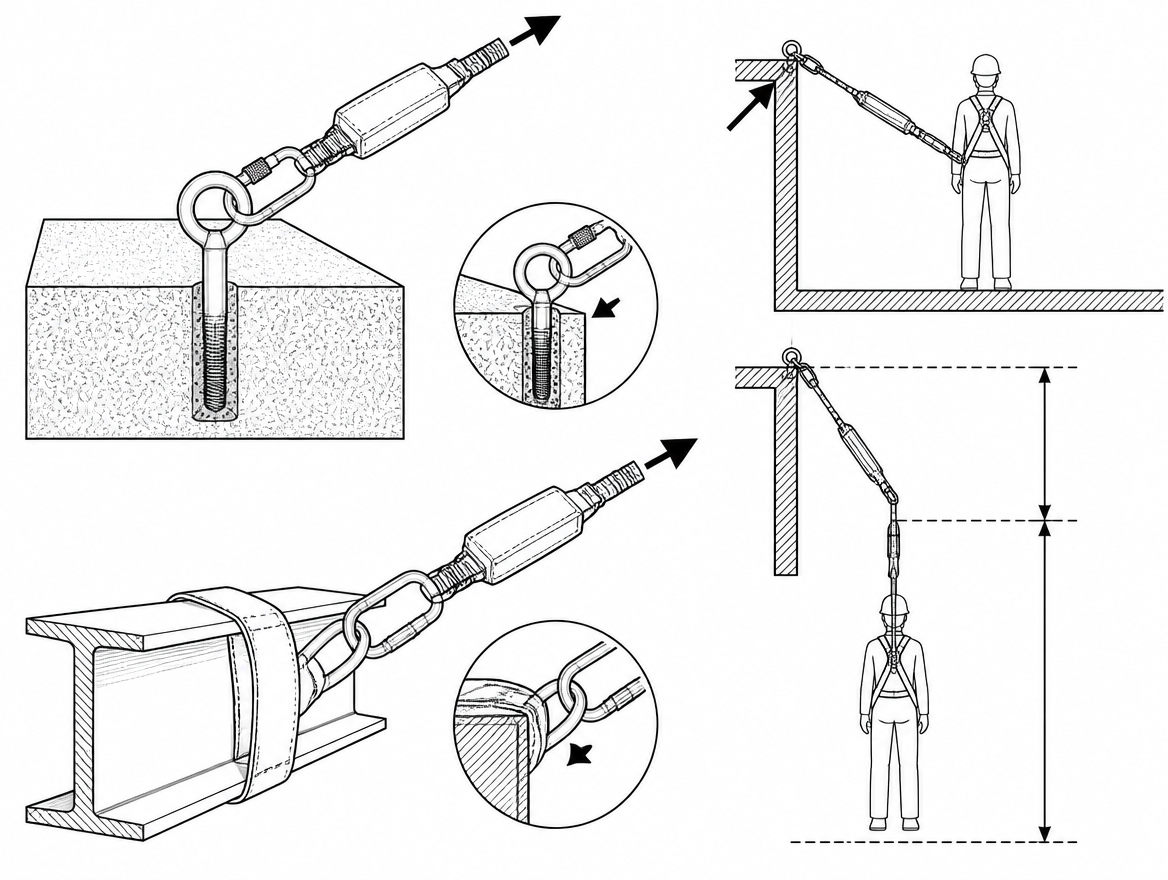
An oblique lanyard or retractable line usually reaches the faller across a parapet, deck edge or steel section. Two consequences follow. First, the line loads onto the edge at an angle rather than square to it, concentrating contact on a short length of webbing or wire and increasing the risk of cutting under dynamic load. Second, friction at the edge divides the system into two tensions; the segment containing the energy absorber may not see enough force to deploy fully, so arrest forces at the harness rise while the absorber remains partly intact after the event.
Where a line will bear on an edge, the controls are edge-qualified equipment, edge protection or sleeving at the contact point, and — where practicable — relocating the anchor so the line no longer crosses the edge at an angle.
Reducing the offset in practice
In order of preference:
- Move the attachment overhead. A rigid rail system to EN 795 Type D, or an overhead structural anchor, keeps the deviation angle small across the whole work area and removes the pendulum from the calculation.
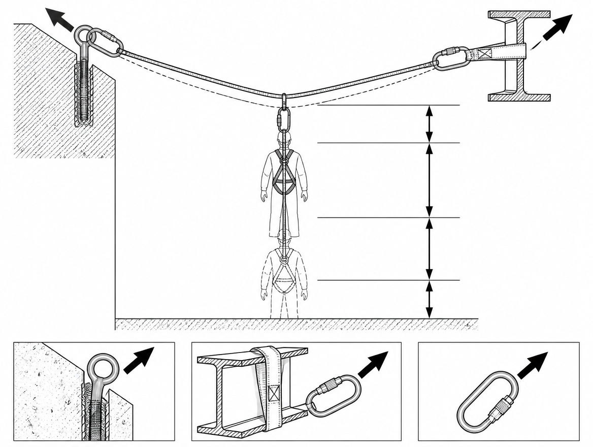
- Use a horizontal anchor line to EN 795 Type C so the attachment point travels with the worker. The deflection of the line under arrest load then has to be added to the clearance calculation; sag is greatest at mid-span and depends on span length, pre-tension and the number of intermediate anchors, so the manufacturer’s clearance tables for the installed configuration are not optional reading. Note also that end and corner anchors on a Type C system see substantially higher forces than the arrest force at the harness.
- Restrain rather than arrest. A correctly length-limited restraint system prevents the person reaching the fall edge, at which point offset and swing become irrelevant. The length must account for the worker’s reach and for the actual anchor position, including any lateral movement.
- Divide the work area. Where a single anchor cannot serve the whole area within its permitted deviation angle, additional anchors and a defined attachment sequence are more reliable than asking a worker to judge an angle by eye.
- Keep the swing path clear. Where an offset is unavoidable, sequencing material storage and plant positions out of the arc is a legitimate and inspectable control.
Documenting the decision
Under an ISO 45001 management system, the selection of an anchor position is a control determination that should be traceable: the anchor location, the components and their stated deployment and clearance figures, the calculated clear space below the anchor, the swept arc, and the rescue arrangements. Rescue matters especially here — a person arrested on an oblique system may end up suspended some metres from the working level and out of reach of the point they fell from, which changes the rescue method and the time to recovery. Suspension intolerance makes that time a design constraint, not a detail.
Takeaway
For any anchor that is not directly overhead, three figures are needed before work starts: the arrest radius from the anchor to the harness attachment point, the horizontal offset at the point of departure from the working level, and the clear space measured on the plumb line below the anchor. Check the swept arc separately, confirm the deviation angle against the instructions for the specific EN 360, EN 353-2 or EN 355 subsystem in use, and verify that the EN 795 anchor device and its fixing are qualified for the direction in which the load will actually arrive. Where the offset exceeds roughly half the arrest radius, the pendulum drop and swing speed rise fast enough that relocating the anchor is normally the correct answer rather than adding margin to the calculation.
Next step: review the manufacturer’s clearance tables for the connecting subsystems held on site against the anchor positions actually available, and record where an overhead anchor, a Type C line or a restraint solution is required instead.
Frequently asked questions
What makes an anchor "oblique"?
An anchor is oblique when a straight line from the anchor to the harness attachment point — normally the dorsal or sternal fall arrest attachment of an EN 361 full body harness — deviates from vertical. Two separate quantities matter: the deviation angle between the connecting subsystem and the vertical, which determines whether the equipment is still inside its tested configuration, and the horizontal offset between the anchor and the point where the person leaves the working level, which determines how much additional vertical drop the pendulum produces.
How much extra vertical drop does a swing fall add?
Once the fall is arrested, the person hangs on a radius R from the anchor to the harness attachment point, and the extra drop as the body swings to the plumb line is R − √(R² − a²), where a is the horizontal offset at arrest. For an arrest radius of 4.00 m, an offset of 1.0 m adds 0.13 m, 2.0 m adds 0.54 m, 3.0 m adds 1.35 m and 3.5 m adds 2.06 m. The first metre or two of offset costs very little clearance, but beyond about half the arrest radius the cost rises sharply.
How fast can a swing fall move the faller sideways?
Horizontal speed at the bottom of the swing is derived from the extra drop by free-fall energy conversion (v = √(2gh)). For a 4.00 m arrest radius the figures are roughly 1.6 m/s at 1.0 m offset, 3.2 m/s at 2.0 m, 5.2 m/s at 3.0 m and 6.4 m/s at 3.5 m — about 23 km/h of horizontal travel into whatever occupies the swing path. Impact against a structure during a swing is not attenuated by the energy absorber, which only controls forces along the axis of the connecting subsystem.
Why does a low or foot-level anchor increase free fall?
Free fall is the distance travelled before the connecting subsystem begins to arrest. With an anchor above the dorsal D-ring, free fall is limited to the slack in the system. With an anchor at foot level, the attachment point must first fall past the anchor before the lanyard can come taut, so free fall approaches the length of the connecting subsystem plus the vertical distance from the anchor up to the D-ring. An energy absorber to EN 355 is qualified to keep arrest force at or below 6 kN under its specified test conditions; feeding it a longer free fall than the manufacturer's stated maximum takes the system outside those conditions.
Where should clearance be measured when the anchor is offset?
With an oblique anchor, required clearance is measured on the plumb line below the anchor, not below the worker, and the swept arc is checked separately — two checks, not one. In the worked example (2.00 m lanyard assembly including EN 362 connectors, 1.75 m maximum absorber deployment, 0.50 m harness stretch and D-ring displacement, giving an arrest radius of 4.25 m, with 1.50 m from D-ring to soles and a 1.00 m safety margin), the depth at first arrest with a 1.80 m offset is 3.85 m below the anchor and 4.25 m at the bottom of the swing, so 6.75 m of clear space is required below the anchor, with the full arc between 1.80 m offset and the plumb line free of obstruction. Where the calculation is close, the offset — not the equipment — is usually the cheapest variable to change.
Need this as a document you can issue? The template library gives you the risk assessments, permits and inspection logs in editable form — and employer plans cover a whole team with completion records.