Safety / Tips and Tricks / Rope access and confined space
Activity 01 · Rope access
Using a Lanyard as a Temporary Anchor: When It Is Permitted, and When It Is Not
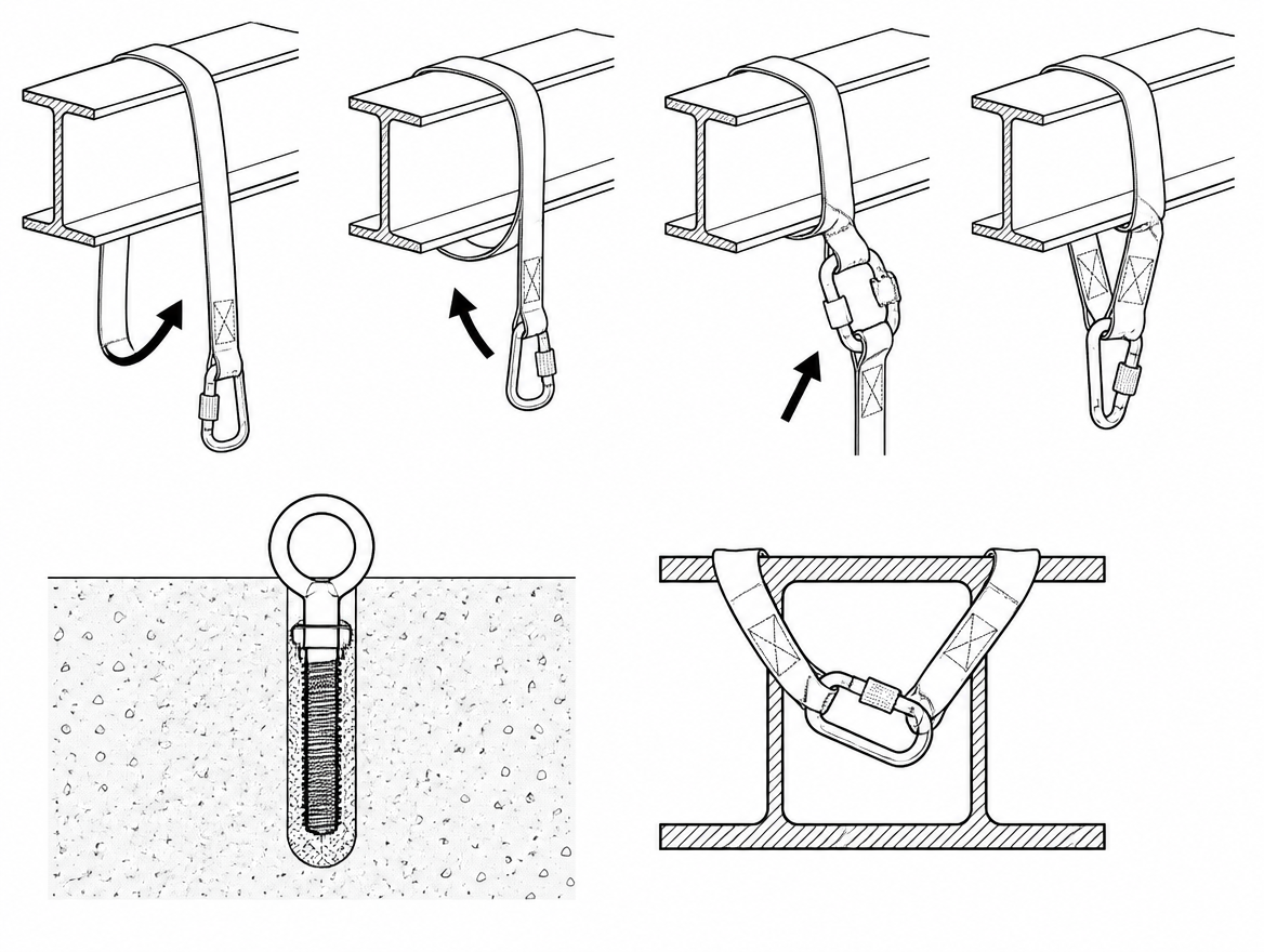
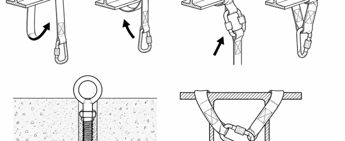
Wrapping a lanyard around a steel beam and clipping it back to itself is one of the most common improvised anchors on site. It takes five seconds, it looks solid, and on most days nothing happens. The problem is that a standard EN 354 lanyard is not an anchor device, and in that configuration the connector is usually loaded across its gate rather than along its spine — the exact orientation in which its rated strength no longer applies. This article sets out what a lanyard is actually rated to do, the narrow case in which a lanyard temporary anchor is a manufacturer-approved configuration, and what to use instead when it is not.
Two different standards, two different jobs
The confusion starts with the fact that a lanyard and an anchor sling can look almost identical: a length of webbing with a loop or a connector at each end. They are certified against different standards, tested in different ways, and marked accordingly.
- EN 354 covers lanyards — the connecting element between the harness and the anchor. A lanyard is tested as a link in a system, not as a device that grips a structure.
- EN 355 covers energy absorbers. In a fall arrest system the lanyard and absorber assembly, including connectors, must not exceed 2 m in total length, and the arresting force transmitted to the user is limited to 6 kN.
- EN 362 covers connectors. Ratings are declared for the major axis with the gate closed and locked; minor-axis and gate-open figures are substantially lower and are given by the manufacturer.
- EN 795:2012 covers anchor devices. Type A is a structural anchor fixed to the structure, Type B is a transportable temporary anchor device, Type C is a horizontal flexible line, Type D a rigid rail, and Type E a deadweight anchor for horizontal surfaces. Static strength testing under EN 795:2012 is 12 kN for anchor devices of metal construction and 18 kN where non-metallic materials such as webbing are used, alongside a dynamic performance test.
An EN 795 Type B anchor sling is designed, tested and marked to be choked around a structural member and loaded from that configuration. An EN 354 lanyard is not, unless its manufacturer explicitly says otherwise.
How an improvised lanyard anchor actually fails
The failure modes are predictable and they compound each other:
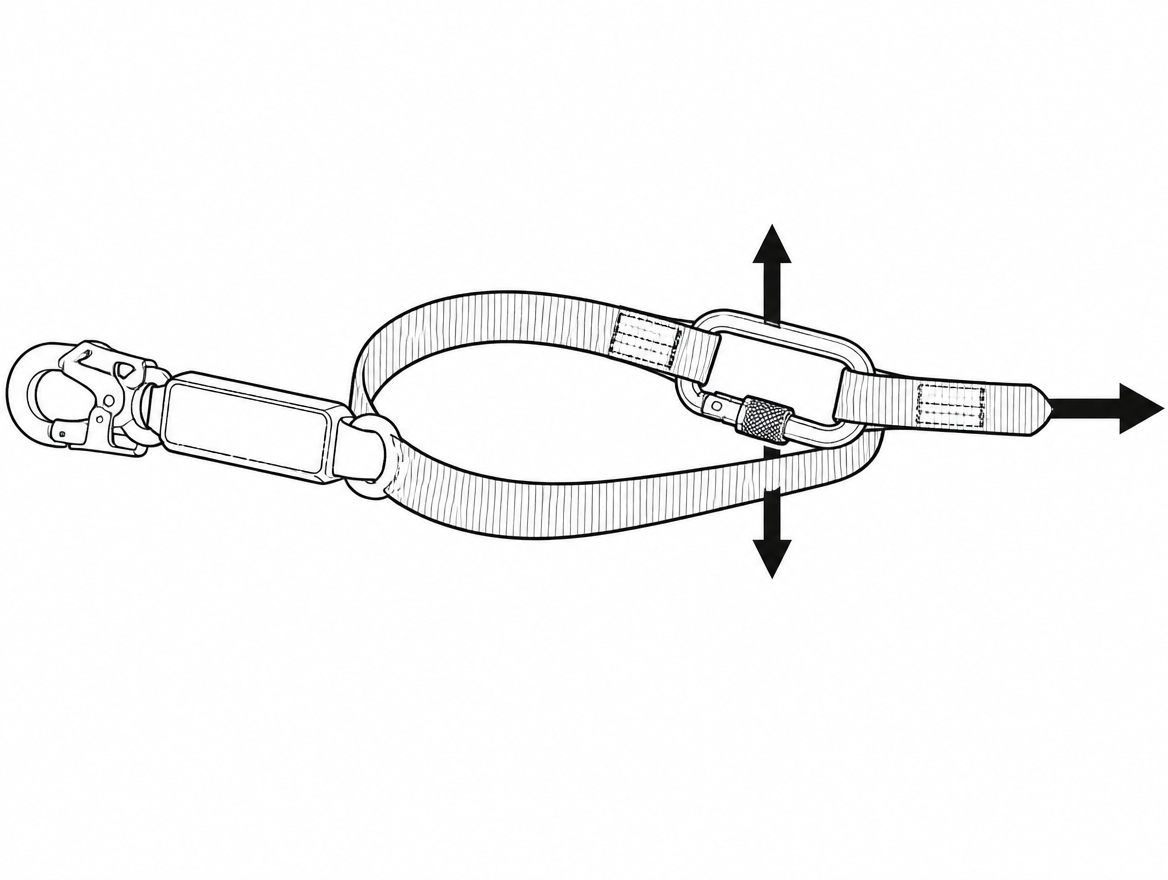
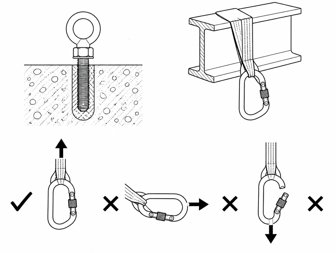
- Cross-gate and minor-axis loading. When a snap hook is clipped back onto the lanyard’s own webbing, the webbing tends to ride into the gate. Under fall arrest loads the gate can be forced or rolled open. The 15 kN class of figures declared under EN 362 apply to the major axis with the gate shut — not to this orientation.
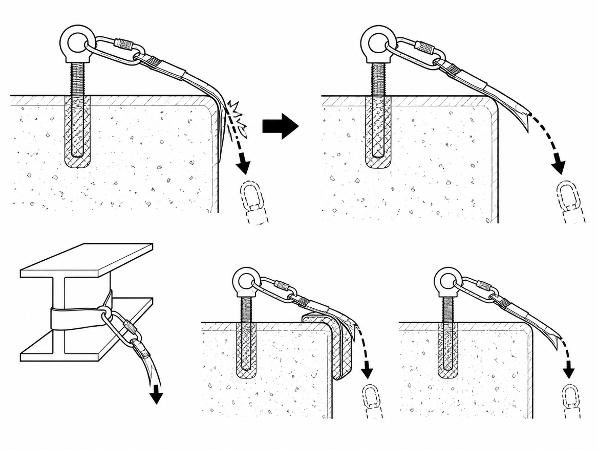
- Abrasion and cutting. Rolled steel flanges, cut ends, purlin cleats and precast concrete corners are far sharper than anything a standard lanyard is tested against. Webbing loaded dynamically over an edge can be severed at loads well below its rated breaking strength.
- Strength loss at the choke. Webbing loses strength wherever it is bent tightly around a small radius or knotted. Knots in lanyards are not permitted unless the manufacturer states otherwise.
- Unknown dynamic behaviour. The dynamic performance test in EN 795 is carried out on the device in its intended installed configuration. A wrapped lanyard has never been tested that way, so nothing about its behaviour under a 6 kN arrest event is verified.
- Structure that was never assessed. A wrap only transfers the problem to the beam, pipe or handrail it is wrapped around. Handrails, cable trays, ductwork and lightweight purlins routinely fail to hold anchor-level loads.
The exception: lanyards specifically rated for tie-back use
Some manufacturers produce lanyards designed to be wrapped around a structural member and connected back to themselves. These are not ordinary lanyards with a note in the manual; they are built for the job and identifiable by specific features:
- A reinforced or abrasion-resistant wrap section, often with a protective sleeve, on the leg that contacts the structure.
- A dedicated tie-back eye or D-ring that the connector clips into — so the connector is loaded along its major axis, on a metal or reinforced interface, not across raw webbing.
- A large-opening connector sized for the structural member, conforming to EN 362, with a locking gate.
- Manufacturer instructions that state the tie-back configuration explicitly, together with any minimum edge radius and minimum structural member dimensions.
Under Regulation (EU) 2016/425 the instructions must be supplied with the product. If the instructions do not describe tie-back use, the configuration is not approved — regardless of how robust the assembly looks on the beam.
What to use instead of an improvised wrap
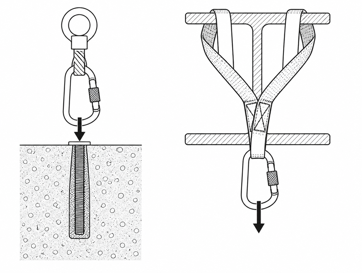
In almost every situation where someone reaches for a lanyard as a makeshift anchor, an EN 795 Type B device does the same job in comparable time:
- Webbing or wire anchor slings (Type B) — choked or wrapped around beams, columns and structural steel, with a rated attachment eye for the connector.
- Beam clamps and beam trolleys (Type B) — sized to the flange width, with the trolley version allowing horizontal travel along the beam.
- Doorway, hatch and window jamb bars (Type B) — for openings within their stated span range.
- Tripods and davit arms (Type B) — for confined space entry and vertical access, usually combined with an EN 360 retractable device with a recovery function.
- Deadweight anchors (Type E) — for flat roofs within the slope limits given in the manufacturer’s instructions.
One planning point for EHS readers: EN 795:2012 addresses anchor devices for use by one person at a time. Where more than one person may be attached to the same device simultaneously, the relevant reference is CEN/TS 16415.
Positioning the anchor: height, swing and edge contact
Choosing a certified device is only half the decision. Where it goes determines what happens in the first second of a fall.
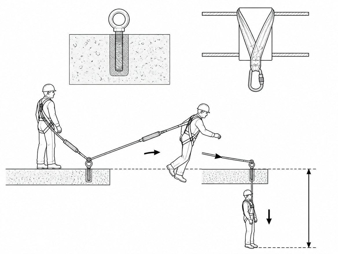
Anchor height. An overhead anchor keeps the free fall short and the fall factor low. An anchor at foot level with a 2 m lanyard produces a factor 2 fall, which not every EN 355 energy absorber is rated to arrest. Confirm the rating in the instructions before planning any foot-level attachment.
Swing fall. The further the user works to the side of the anchor, the wider the pendulum. A swing carries the user into structure at speed and increases the effective fall distance. Keep work within the angle stated by the manufacturer, or move the anchor.
Edges. If the lanyard can pass over an edge in a fall, either the equipment must be tested and approved for edge use over an edge of the relevant radius, or the edge must be protected, or the anchor must be repositioned so contact is impossible.
Working out the clearance below
A correct anchor and a correct connection still leave one calculation to do. The required clearance below the working level is built from:
- the length of the lanyard assembly (up to 2 m under EN 355);
- the deployment of the energy absorber, taken from the manufacturer’s figure — typically up to 1.75 m;
- the distance from the harness dorsal attachment to the user’s feet, commonly around 1.5 m;
- harness stretch and attachment element shift;
- a safety margin below the feet, commonly 1 m.
If the sum exceeds the actual clearance to the ground or the nearest obstruction, fall arrest with a 2 m lanyard is the wrong system for that position. A retractable type fall arrester to EN 360, a restraint system that prevents reaching the edge, or a repositioned overhead anchor are the alternatives to assess.
Inspection and records
Anchor slings, connectors and lanyards are all personal fall protection equipment and fall under the same regime. EN 365 requires periodic examination by a competent person at intervals of no more than 12 months, with the manufacturer’s instructions and the severity of use potentially requiring shorter intervals. Pre-use checks are carried out by the user before every use.
On a temporary anchor sling, the pre-use check focuses on: cuts, fraying, glazing or heat damage to the webbing; distortion, cracks or corrosion at the metal eye; connector gate and lock function; legibility of the markings and presence of the identification; and evidence of previous loading. Any device that has arrested a fall is withdrawn from service until the manufacturer or a competent person has assessed it. Withdraw first, document second — a device left in the bag with a mental note is a device that goes back up the ladder.
Field decision checklist
- Does the equipment’s own instruction manual describe the tie-back or wrap configuration? If not, do not use it that way.
- Is the connector loaded along its major axis, with the gate closed and locked, onto a rated eye or D-ring — never across raw webbing?
- Is the structural member itself capable of the anchor load, and has someone competent confirmed that?
- Is the anchor as high as the work allows, and is the user working within the permitted angle?
- Can the line contact an edge in a fall, and if so is the equipment approved for that edge or is the edge protected?
- Does the calculated clearance fit in the space actually available below?
- Is there a rescue plan that can be executed for this anchor position, with the equipment on site now?
The short version
A lanyard is a connecting element, not an anchor device. Only a lanyard whose manufacturer specifically approves tie-back use — with a reinforced wrap leg, a dedicated tie-back attachment and a suitable large-opening connector — may be wrapped around a structure and clipped back to itself. For everything else, an EN 795 Type B transportable anchor device is the correct and equally quick answer.
A practical next step: take an inventory of the temporary anchor devices actually carried in each work vehicle or site store, check each one against EN 795:2012 Types B and E and its own instruction manual, and confirm that the range on site covers the structural members crews are genuinely working around — beams, columns, openings and flat roofs alike. Where a crew has been improvising, the gap is usually in the kit list, not in the crew.
Frequently asked questions
Can I wrap a standard EN 354 lanyard around a beam and clip it back to itself?
No. A standard EN 354 lanyard is not an anchor device. In that configuration the connector is usually loaded across its gate rather than along its spine, which is the exact orientation in which its rated strength no longer applies. The only exception is where the manufacturer's instructions explicitly describe tie-back use.
What is the difference between an EN 354 lanyard and an EN 795 Type B anchor sling?
They can look almost identical, but they are certified against different standards and tested in different ways. An EN 354 lanyard is tested as a link in a system, not as a device that grips a structure. An EN 795 Type B anchor sling is designed, tested and marked to be choked around a structural member and loaded from that configuration.
How does an improvised lanyard anchor actually fail?
The article lists five compounding failure modes: cross-gate and minor-axis loading, where webbing rides into the gate and the gate can be forced or rolled open under fall arrest loads; abrasion and cutting on sharp flanges, cut ends, purlin cleats and precast corners; strength loss where webbing is bent tightly around a small radius or knotted; unknown dynamic behaviour, because the wrapped configuration has never been dynamically tested; and structure that was never assessed, such as handrails, cable trays, ductwork and lightweight purlins.
How can I tell if a lanyard is genuinely rated for tie-back use?
Purpose-built tie-back lanyards have identifiable features: a reinforced or abrasion-resistant wrap section, often with a protective sleeve, on the leg contacting the structure; a dedicated tie-back eye or D-ring so the connector is loaded along its major axis on a metal or reinforced interface; a large-opening connector conforming to EN 362 with a locking gate; and manufacturer instructions stating the tie-back configuration explicitly, with any minimum edge radius and minimum structural member dimensions. Under Regulation (EU) 2016/425 the instructions must be supplied with the product, and if they do not describe tie-back use, the configuration is not approved.
What should be used instead of an improvised wrap?
In almost every case an EN 795 Type B device does the same job in comparable time: webbing or wire anchor slings choked around beams, columns and steel; beam clamps and beam trolleys sized to the flange width; doorway, hatch and window jamb bars within their stated span range; tripods and davit arms for confined space and vertical access; or Type E deadweight anchors for flat roofs within the manufacturer's slope limits.
Need this as a document you can issue? The template library gives you the risk assessments, permits and inspection logs in editable form — and employer plans cover a whole team with completion records.