Safety / Tips and Tricks / Rope access and confined space
Activity 01 · Rope access
Remote Control of a Descender Handle with a Cord: Rigging, Limits and Failure Modes
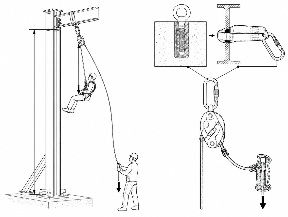
Remoting a descender handle with a cord puts the control point somewhere other than the device: a rescuer at the base of a mast operating a descender rigged 30 m above, or a technician on the ground lowering a suspended colleague whose own descender is on their harness. The technique is attractive because it solves an access problem instantly. It also removes the two things that normally make a descent controllable — a hand on the brake side of the rope and direct tactile feedback of rope speed — and it introduces a slim, low-strength cord into a system where a snag can hold a handle open. This article sets out where the technique appears, what actually fails, and what the applicable EN standards and the device instructions for use do and do not permit.
The two configurations where a remote cord appears
Almost every real-world use falls into one of two rigging patterns, and they behave differently.
Descender at the anchor, load on the rope, operator remote
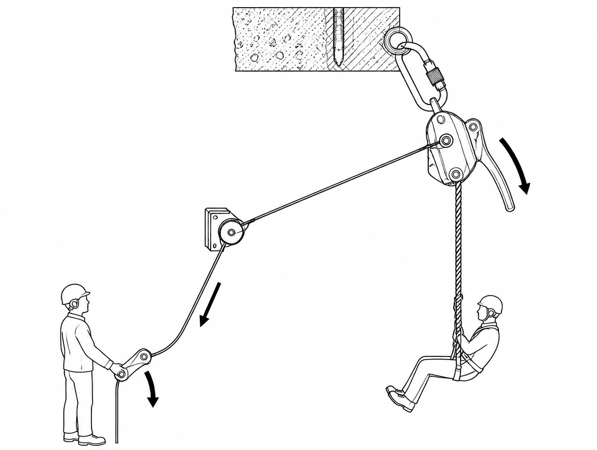
The descender is fixed at the anchor or on a rigging plate, the rope runs from the device down to the load, and a cord runs from the handle to an operator standing clear — typically because the anchor is inaccessible, exposed, or in a position with no sightline to the load. The load descends when the handle is opened; the device provides the braking friction. In this configuration nobody is holding the free end of the rope unless a second operator is positioned to do so.
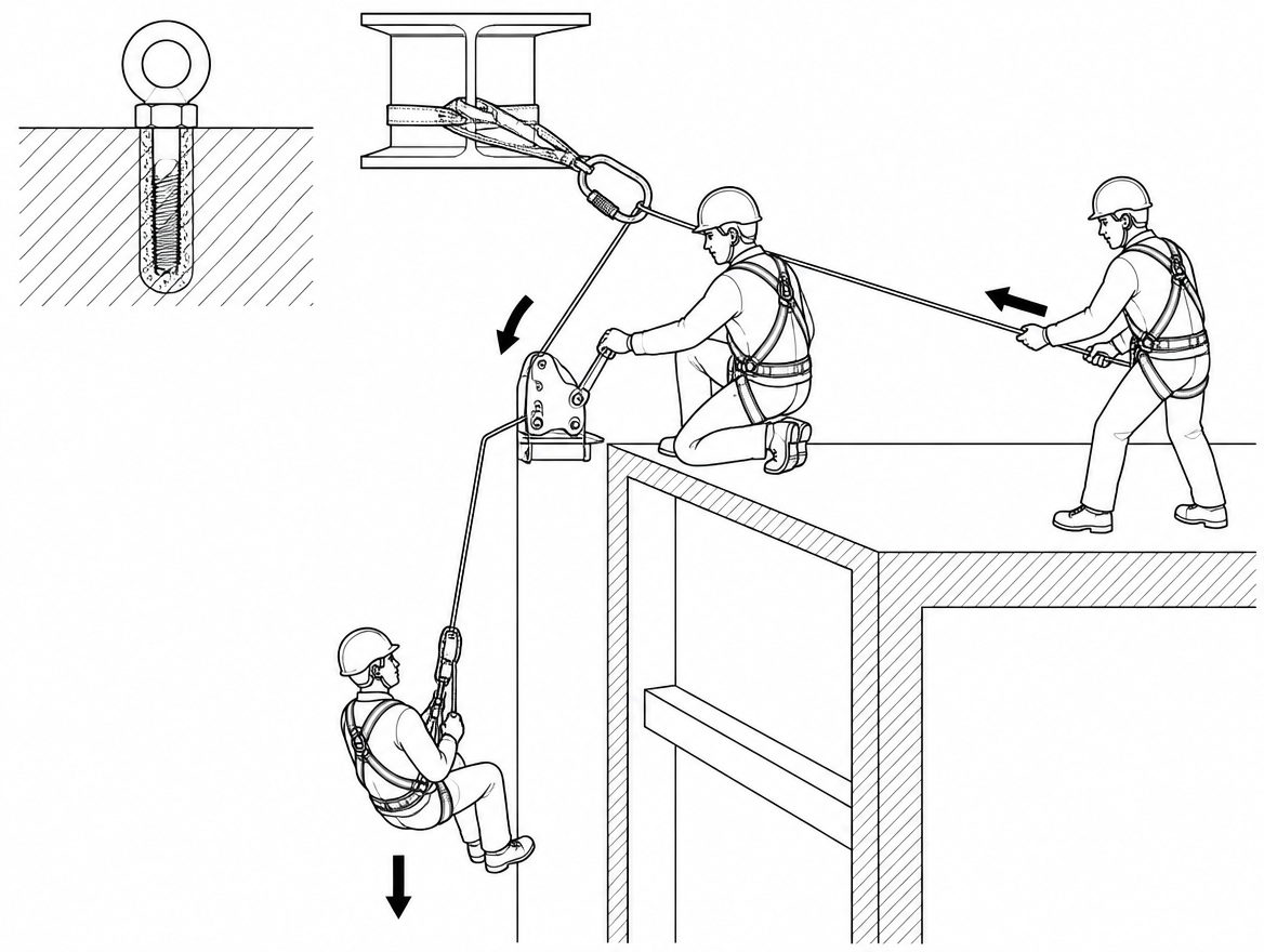
Descender on the suspended person, cord to a rescuer below
Used when a rope access technician is incapacitated on their own descender and a rescuer below can reach a cord but not the casualty. The rescuer pulls to open the handle and lower the casualty to the ground. Here the geometry changes continuously: the cord angle at the handle swings as the load descends, and the rescuer is directly beneath a moving load.
Handle geometry decides whether the cord works at all
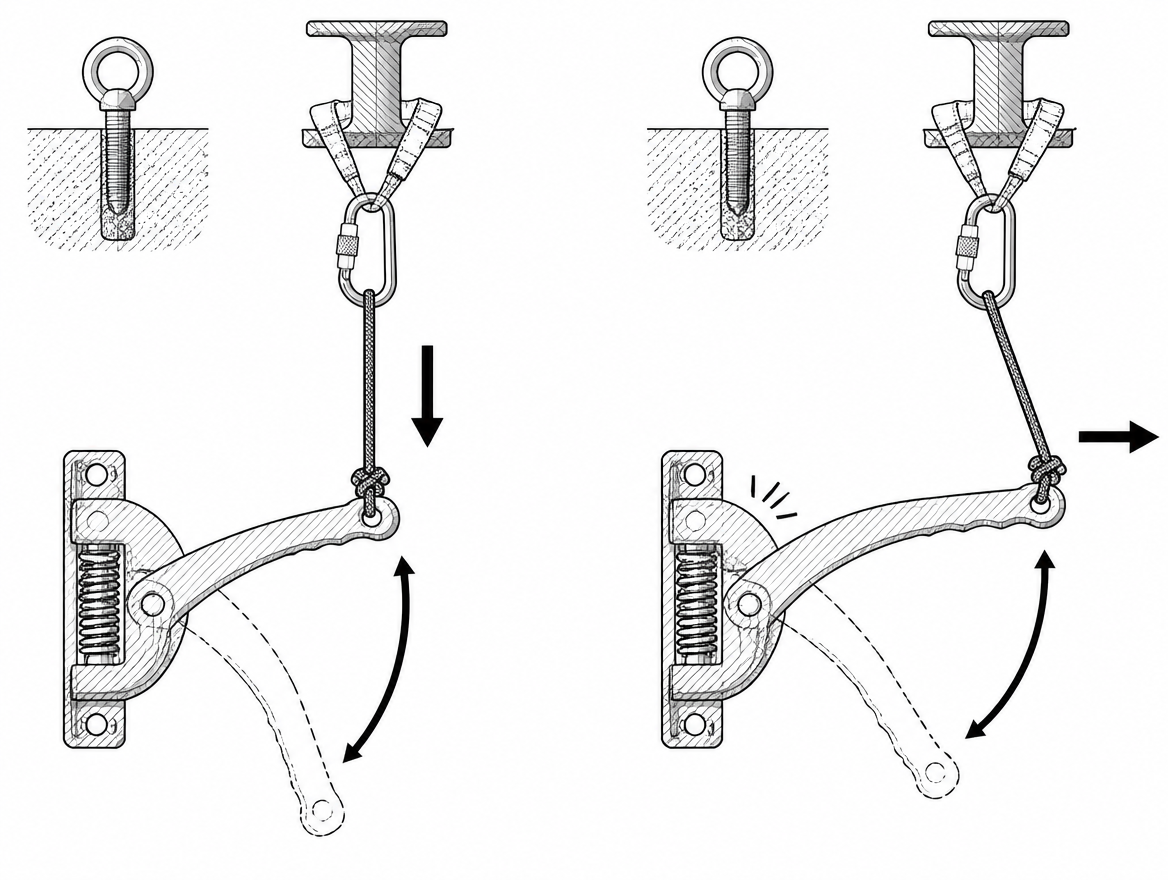
A descender handle is designed to be moved through an arc by a hand positioned on the device. The return spring, the cam geometry and, on devices fitted with an anti-panic function, the over-travel behaviour are all calibrated for force applied in that plane. A cord pulling from an arbitrary direction produces three predictable problems:
- Off-plane loading. A sideways or downward pull can bind the handle on its axle, deform it, or move it through only part of its travel, so the cam never reaches the intended friction setting.
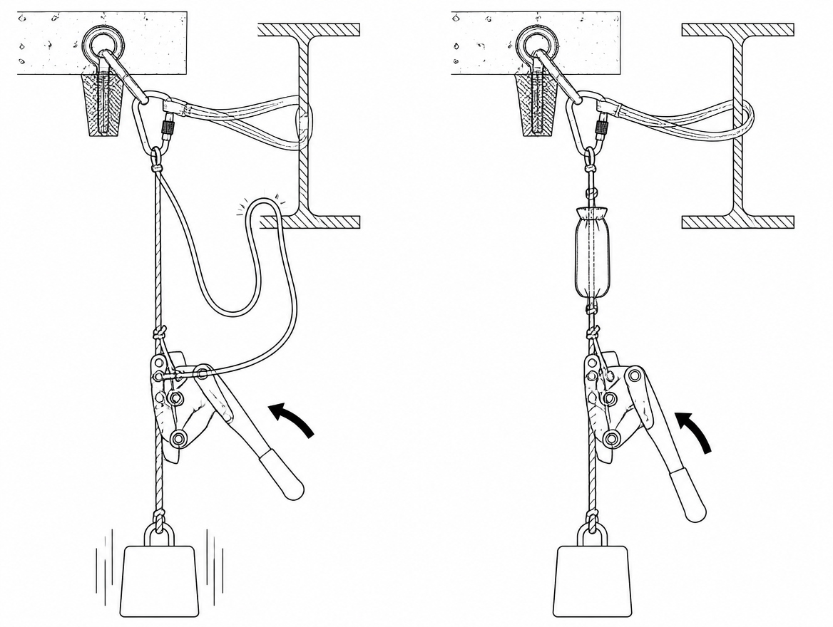
- Incomplete return. The braking position depends on the handle returning fully under spring force. A cord that runs over an edge, or a long cord whose hanging mass pulls on the handle, biases it toward the open position. On a long drop, the self-weight of the cord alone can be enough to prevent full return.
- Anti-panic over-travel. On devices with an anti-panic function, pulling the handle beyond the descent range re-engages braking. A remote operator with no feel for handle position tends to over-pull, stall the descent, release, and produce a stop-start lowering with impact loading at each restart.
The practical mitigation is a small deviation connector placed on the device or on the anchor plate so that the cord always leaves the handle in the plane of its travel, regardless of where the operator stands. That connector also takes the hanging weight of the cord off the handle.
What is given up: brake-side rope control
The instructions for use of many descender devices certified to EN 12841:2024 Type C, and of rescue descenders certified to EN 341:2011, require the free end of the rope to be held during descent. That requirement is not decoration: holding the brake side adds friction outside the device, gives the operator an immediate reading of rope speed, and provides a second means of stopping if the handle is released late.
A remote-handle configuration with nobody on the brake side operates the device outside the conditions its instructions describe. Descent speed is then governed only by handle position, rope diameter and condition, load mass, and the amount of heat already in the device — none of which the remote operator can sense. Where the technique is used at all, the brake side is normally tended by a second operator or controlled by a friction hitch, so that the cord modulates friction and a person still controls the rope.
Failure modes to plan for
- Snagged cord holding the handle open. A cord caught on a bolt head, a ladder rung, a cable tray or the moving rope can hold the handle in the descent position with no operator input. The result is an uncontrolled lowering to the length of the rope.
- Cord wrapped around the running rope. A slack loop can be drawn into the device with the rope, jamming the cam or being cut.
- Cord entering the load path. Accessory cord is not a lifeline. It becomes a hazard the moment anyone treats it as a handline, clips into it, or uses it to pull a load into position.
- Elongation and drag masking the handle position. Over a long run, cord stretch plus friction over edges means the operator feels their own system, not the handle. Fine modulation becomes guesswork.
- Heat. Rope-bearing surfaces heat up during descent. A synthetic cord resting against the device body or the sheave can be weakened or melted.
- Loss of sightline. The reason for remoting the handle is often the same reason the operator cannot see the load, which removes the only remaining feedback channel.
Where the standards actually land
No EN standard describes remote actuation of a descender handle as a certified mode of use. What the framework does provide is the boundary conditions:
- EN 12841:2024 covers rope adjustment devices for rope access. Type C devices are work-line descenders and are not fall arrest devices; the system requires a separate safety line fitted with a Type A back-up device. Type C devices are certified with semi-static kernmantle rope to EN 1891 Type A within the diameter range stated in the instructions for use.
- EN 341:2011 covers descender devices for rescue, classified by descent energy. A device certified only to EN 12841 Type C is not automatically a rescue lowering device, and the reverse also holds.
- EN 365:2004 sets the general requirements for instructions for use, marking, and periodic examination — including examination by a competent person at intervals not exceeding 12 months, and more frequently where use conditions warrant it.
- The instructions for use supplied with the specific device are the deciding document. Some manufacturers publish technical notices covering remote or two-person operation of a named device; others prohibit any actuation other than by hand on the device. A generic technique description does not override either.
- ISO 45001:2018 puts the organisational requirements around it: hazard identification and control determination under clause 6.1.2, competence under clause 7.2, and emergency preparedness and response under clause 8.2 — which is where a rescue plan that depends on a remote-handle lowering has to be documented and rehearsed.
The connectors, harness and anchor in the system carry their own conformity requirements: EN 362 for connectors, EN 361 for the full body harness (with EN 813 for the sit harness element used in rope access), and EN 795 for anchor devices. The cord itself sits outside all of this, which is precisely why it must never be load-bearing.
Rigging the cord where the risk assessment supports it
Where a documented assessment, the device instructions and a competent person support the technique, the following details separate a workable rig from a hazard:
- Attachment to the handle. A girth hitch or slip knot at the point on the handle intended to receive hand force, snug enough that it cannot migrate toward the axle. A connector clipped through a handle aperture adds a lever arm and can bind against the device body.
- Cord selection. Commonly 4 mm to 6 mm accessory cord — large enough to grip and pull without cutting into the hand, small enough not to add significant hanging mass. A colour clearly distinct from every rope in the system reduces the chance of anyone loading it by mistake.
- Deviation at the device. A small connector on the device or rigging plate that keeps the line of pull in the plane of the handle arc and carries the cord’s self-weight.
- Cord management. The run kept short, tensioned or bagged, clear of the running rope, structure, and hot surfaces. Slack loops are the mechanism behind most snag events.
- Brake-side control retained. A second operator on the free end of the rope, or a friction hitch on the brake side, so that releasing the cord is not the only way to stop the load.
- Independent back-up on the load. A separate safety line with an EN 12841 Type A back-up device, in line with the requirement that a Type C descender is not a fall arrest device.
- Function test under representative load. Handle travel, full spring return, and stopping distance verified with a mass equivalent to the intended load, in a controlled environment, before the method is relied on.
- Communication. A direct sightline to the load, or a dedicated voice link and agreed commands, with one person holding the authority to stop.
One design consideration worth resolving explicitly during the assessment: a cord chosen to be weak relative to the system will part rather than hold a handle open indefinitely if it snags, and the device then defaults to its braking position. That fail-safe behaviour is only useful if the plan already covers what happens next — an operator with a broken cord has no remaining control over the lowering.
Alternatives that usually beat remoting the handle
The access problem that motivates a remote cord can often be solved without giving up brake-side control:
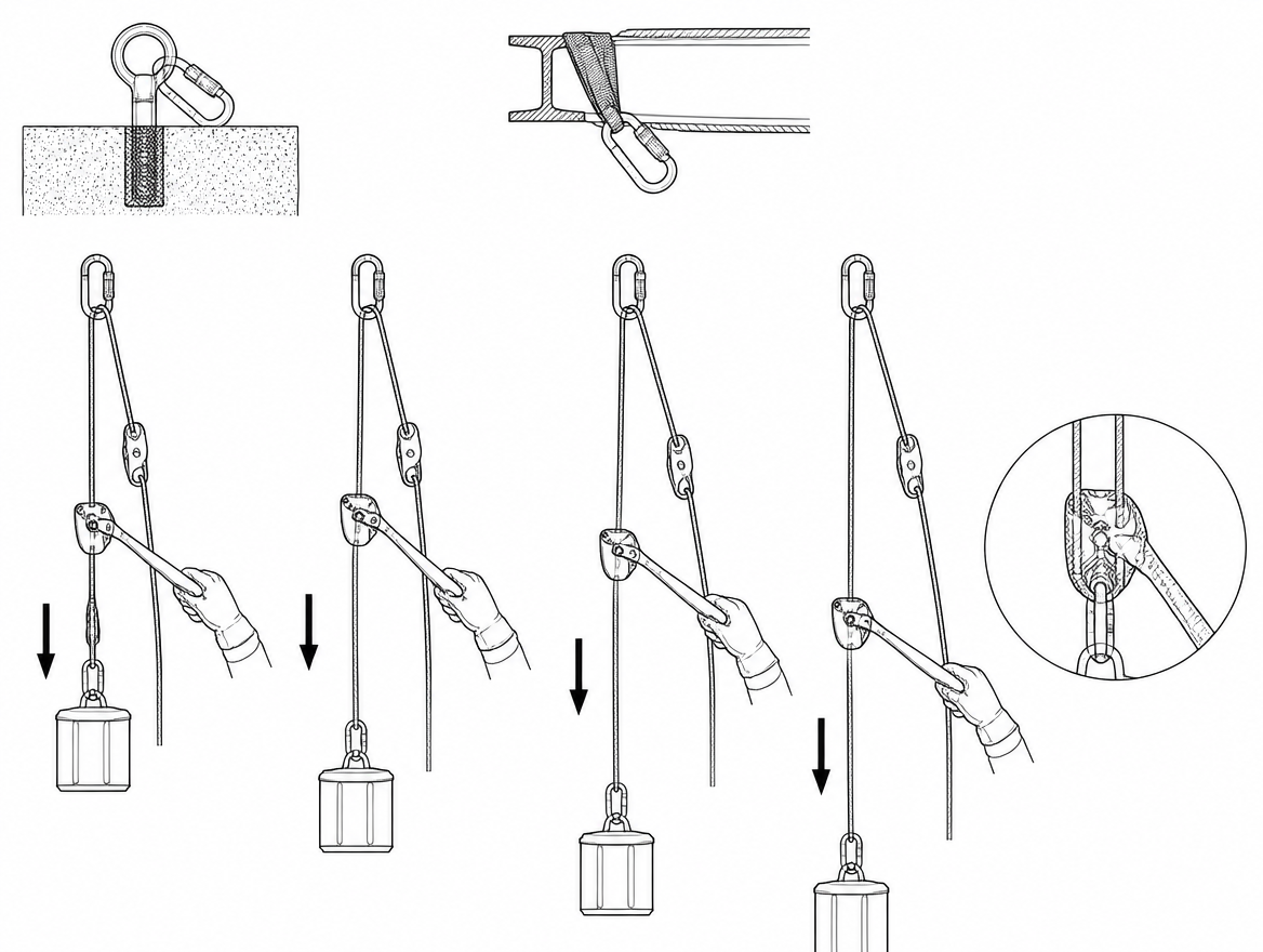
- Remote the rope, not the handle. Bring the brake side of the rope down through a deviation to the operator’s position. The operator then controls real friction and feels rope speed, with the device still hand-operated by whoever rigged it — or replaced by a lowering configuration designed for that layout.
- Reposition the descender. Moving the device from an inaccessible anchor to a rigging plate at a workable stance removes the need for a cord entirely.
- Pick-off with direct control. For a suspended casualty, a rescuer descending to the casualty with a pick-off strap operates the descender by hand, with the casualty’s weight transferred to the rescuer’s system.
- Two-person operation as documented by the manufacturer. Where a device has a published technical notice for assisted or remote operation, following that notice is preferable to improvising a cord rig.
Pre-use checks and post-use inspection points
Alongside the normal pre-use check required by EN 365:2004 and the device instructions, a remote-handle configuration adds specific checks:
- Handle returns fully to the braking position under spring force alone, with the cord attached and the cord run in place — not just with the cord removed.
- Handle shows no deformation, no play on its axle, and no scoring or abrasion where the cord bears.
- Cam and friction surfaces within the wear limits given in the instructions; rope diameter within the certified range.
- Cord free of glazing, abrasion, or heat damage. The cord is a consumable and is replaced on any doubt rather than assessed.
- After use, the device inspected for heat marks and the cord run inspected for the edges or fixtures it contacted, which indicates where a snag would occur next time.
Records of periodic examination remain due at intervals not exceeding 12 months under EN 365:2004, and any device that has arrested a fall or taken an uncontrolled descent is withdrawn from service pending examination by a competent person.
Takeaway
A cord on a descender handle is a control extension, not a control system. It works only when the pull stays in the plane of the handle arc, the cord cannot snag or hang on the handle, someone still controls the brake side of the rope, and the load is on an independent back-up. Before the method enters a rescue plan under ISO 45001:2018 clause 8.2, the deciding step is reading the instructions for use of the specific descender to establish whether the manufacturer permits actuation by anything other than a hand on the device — and, where they do not, redesigning the lowering rather than the handle.
Related reading on this site: descender selection under EN 12841 Type C versus EN 341:2011, and building a rope rescue plan that satisfies ISO 45001:2018 clause 8.2.
Frequently asked questions
What are the two rigging configurations where a remote cord on a descender handle appears?
Almost every real-world use falls into one of two patterns. In the first, the descender is fixed at the anchor or on a rigging plate, the rope runs down to the load, and a cord runs from the handle to an operator standing clear — typically because the anchor is inaccessible, exposed, or has no sightline to the load. In the second, the descender is on a suspended, incapacitated technician and a rescuer below pulls a cord to open the handle and lower the casualty; here the cord angle at the handle swings as the load descends and the rescuer is directly beneath a moving load.
Why does pulling a descender handle with a cord cause problems with handle geometry?
A handle is designed to be moved through an arc by a hand on the device, and the return spring, cam geometry and any anti-panic over-travel behaviour are calibrated for force applied in that plane. A cord produces three predictable problems: off-plane loading, which can bind the handle on its axle, deform it or move it through only part of its travel so the cam never reaches the intended friction setting; incomplete return, because a cord running over an edge or a long cord's hanging mass biases the handle toward open — on a long drop the cord's self-weight alone can prevent full return; and anti-panic over-travel, where a remote operator with no feel for handle position over-pulls, stalls the descent, releases, and produces stop-start lowering with impact loading at each restart.
How can the cord be routed so it works correctly?
The practical mitigation is a small deviation connector placed on the device or on the anchor plate so the cord always leaves the handle in the plane of its travel, regardless of where the operator stands. That connector also takes the hanging weight of the cord off the handle. The correct arrangement is a cord tied to the handle where hand force is intended, routed so the pull stays in the plane of the handle arc, and kept short, tensioned and bagged, clear of bolts, edges and the running rope.
What is lost when nobody holds the brake side of the rope?
The instructions for use of many descenders certified to EN 12841:2024 Type C, and of rescue descenders certified to EN 341:2011, require the free end of the rope to be held during descent. Holding the brake side adds friction outside the device, gives an immediate reading of rope speed, and provides a second means of stopping if the handle is released late. Without it, descent speed is governed only by handle position, rope diameter and condition, load mass and the heat already in the device — none of which the remote operator can sense. Where the technique is used, the brake side is normally tended by a second operator or controlled by a friction hitch, so the cord modulates friction while a person still controls the rope.
Which failure modes should be planned for with a remote cord?
A cord snagged on a bolt head, ladder rung, cable tray or the moving rope can hold the handle open with no operator input, giving an uncontrolled lowering to the length of the rope. A slack loop can be drawn into the device with the rope, jamming the cam or being cut. Accessory cord is not a lifeline and becomes a hazard if treated as a handline, clipped into, or used to pull a load. Cord stretch and friction over edges mask handle position so fine modulation becomes guesswork. Rope-bearing surfaces heat up during descent, so a synthetic cord resting against the device body or sheave can be weakened or melted. Finally, the reason for remoting the handle often means the operator cannot see the load, removing the last feedback channel.
Need this as a document you can issue? The template library gives you the risk assessments, permits and inspection logs in editable form — and employer plans cover a whole team with completion records.