Safety / Tips and Tricks / Rope access and confined space
Activity 01 · Rope access
Belaying with a Winch-Descender: Rigging, Slack Control and Fall Capture
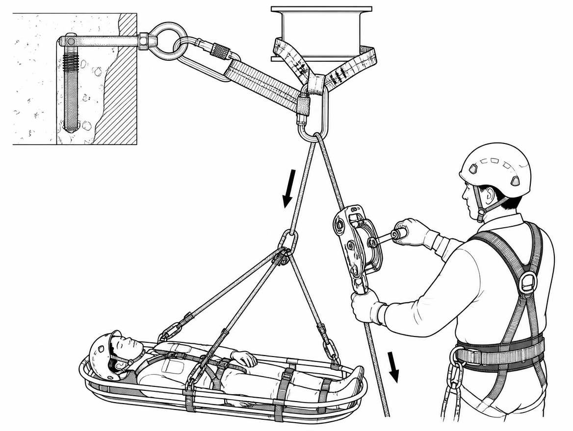
A winch-descender belay is the difference between a caught fall and a stalled rescue. When a stretcher, a casualty or a worker on a raise is held by a self-braking lowering device rather than a plain backup device, the team that catches a main-line failure can immediately continue the job in the other direction – lowering the load under control on the belay line without a changeover, without building a new system, and without leaving the load hanging while hardware is swapped. That capability is also the risk: a device built to lower loads is easy to mis-rig, easy to hold open at the wrong moment, and easy to operate with more slack in the line than the rope system can absorb. This article covers how a winch-descender is rigged and operated as a belay, what the EN framework does and does not certify it for, and the specific errors that degrade the function.
Scope: where a winch-descender belay applies
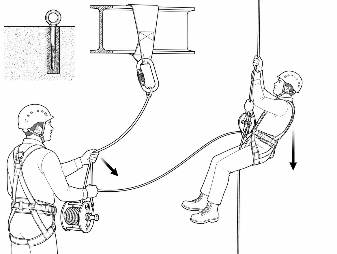
Terminology matters here, because “belay” is used loosely across disciplines. In EN-standards rope access work, a person on personal ropes uses a working line with a descender or ascender and a separate safety line fitted with a Type A backup device to EN 12841. A winch-descender is not a Type A backup device and does not substitute for one.
The winch-descender belay belongs to load lines operated by a team:
- Raising or lowering a stretcher, rescue frame or casualty on a two-line system.
- Confined space entry and retrieval where the entrant is on a main line and a second, independently anchored line.
- Lowering plant, tooling or a suspended load where a secondary line is required and must remain operable under load.
In each case, one line carries the load and a second line is tended by an operator who keeps it clear of slack and ready to arrest. The winch-descender sits on that second line.
What the device is certified for, and what it is not
Devices in this class – self-braking lowering and hauling devices with an integral progress-capture cam, a release handle and, in most current models, an anti-panic function – typically carry more than one certification. Reading them accurately determines what the device may legally and safely be used for:
- EN 341 – descender devices for rescue. Defines classes by descent energy and states a rated load and maximum descent height. This is the certification that covers lowering a person.
- EN 12841 Type C – rope adjustment device, descender, for rope access work on a working line.
- EN 1496 – rescue lifting devices, where the device is certified for raising a person.
- EN 12278 – applies to pulleys, relevant where the device incorporates or is used with a swing-side sheave.
What is almost never printed on a device of this type is a certification for arresting a free fall. There is no EN product standard that certifies a winch-descender as a fall-arrest component in the sense of EN 363 fall-arrest systems, and none of the certifications above imply an energy-absorbing function. The device’s ability to hold a suddenly applied load is a manufacturer-declared performance characteristic, not a harmonised requirement, and the numbers – maximum rated load, maximum load for two-person or rescue use, declared slip or peak-force behaviour – differ between models. Those figures are in the instructions for use supplied with the device under EN 365, and they are the only authoritative source for the specific device on the anchor.
The practical consequence: the system’s protection against high arrest forces comes from keeping the fall factor near zero, not from the device. EN 1891 Type A low-stretch kernmantle rope, which is the correct rope for these systems, absorbs very little energy by design. Slack in the belay line is the single largest variable the operator controls.
Rope, connectors and anchors
Compatibility is stated by the device manufacturer and is not interchangeable between models:
- Rope: EN 1891 Type A low-stretch kernmantle within the exact diameter range marked on the device and stated in its instructions. Many devices in this class are specified for 10.5–11.5 mm; some accept a wider or narrower band. A rope below the stated range slips in the brake mechanism; a rope above it binds and can defeat the release handle.
- Rope condition: glazed, fused or heavily contaminated sheath alters friction unpredictably. A rope that has been used repeatedly for fast lowers is not automatically fit for belay duty.
- Connectors: EN 362 connectors, screw-gate or automatic locking, sized so the device sits in the long axis of the connector and cannot ride up onto the gate.
- Anchors: anchor devices to EN 795 selected for the anticipated load, including a two-person rescue load where that applies. Static strength requirements differ by anchor type and by whether the anchor is metallic or textile, so the figure that governs is the one in the anchor device’s own certification and instructions, not a general assumption. Where reasonably practicable, the belay line is rigged to an anchor independent of the main line.
- Rope end: a stopper knot in the tail of the belay line, and enough rope on the ground or in the bag to complete a full lower to a safe landing.
- Edges: edge protection or a deviation on both lines. A belay line that abrades through during a raise removes the only redundancy in the system.
Rigging the device as a belay
Rope direction is the error with the shortest path to failure, because a device threaded backwards will still accept the rope, still close, and still feel plausible in the hand – until it is loaded.
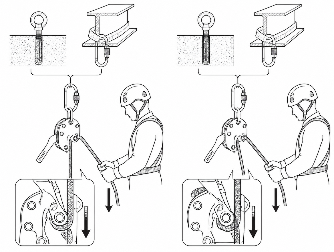
- Fix the device to the anchor connector and check that the device body is free to align with the direction of pull, without being pressed against structure, sling or anchor plate.
- Thread the rope in the direction indicated by the moulded or engraved orientation features on the device body, so that the load strand enters on the load side and the free strand exits on the brake side.
- Close and lock the moving side plate and the connector gate. Confirm the plate is fully seated, not held by friction alone.
- Function test under load, every time: load the device with body weight or with the load itself held on a separate means, then pull on the load strand and confirm the cam engages and the rope does not run. Then confirm the release handle produces controlled movement and returns to the braking position when released.
- Confirm the anti-panic function, where fitted, behaves as described in the instructions. Anti-panic is a secondary feature that arrests over-rotation of the handle; it does not replace a brake hand and it is not a substitute for the function test.
Managing slack while a load is being raised
During a raise, the belay operator’s task is to take in rope at the same rate the hauling team gains it, keeping the belay line just short of tensioned. The target is the smallest amount of slack that still allows the main line to carry the load cleanly – in practice a short, visible catenary rather than a taut line, and never a loop hanging below the load.
- The brake-side strand stays in a gloved hand at all times. Rope is pulled through the brake side, not fed from the load side.
- The release handle is not held open during a raise. A hand resting on the handle, or a handle kept partly open to reduce friction while taking in rope, leaves the cam unable to engage at the moment it is needed.
- Where the device’s friction makes taking in rope difficult, the correct remedy is the one the manufacturer provides – correct rope diameter, a redirect, or a device configuration intended for that direction of travel – not defeating the brake.
- Slack accumulates fastest at transitions: at an edge, at a knot pass, at a mid-point rebelay, and at the moment the hauling team resets a progress capture. Those are the points where the belay operator stops the raise rather than working through it.
- Excess slack is removed while the load is stationary and supported, not while it is moving.
A belay line with a metre of slack over a rescue load, on low-stretch rope, produces forces that are hard to predict and that no part of the system is designed to absorb. Slack control is the control measure.
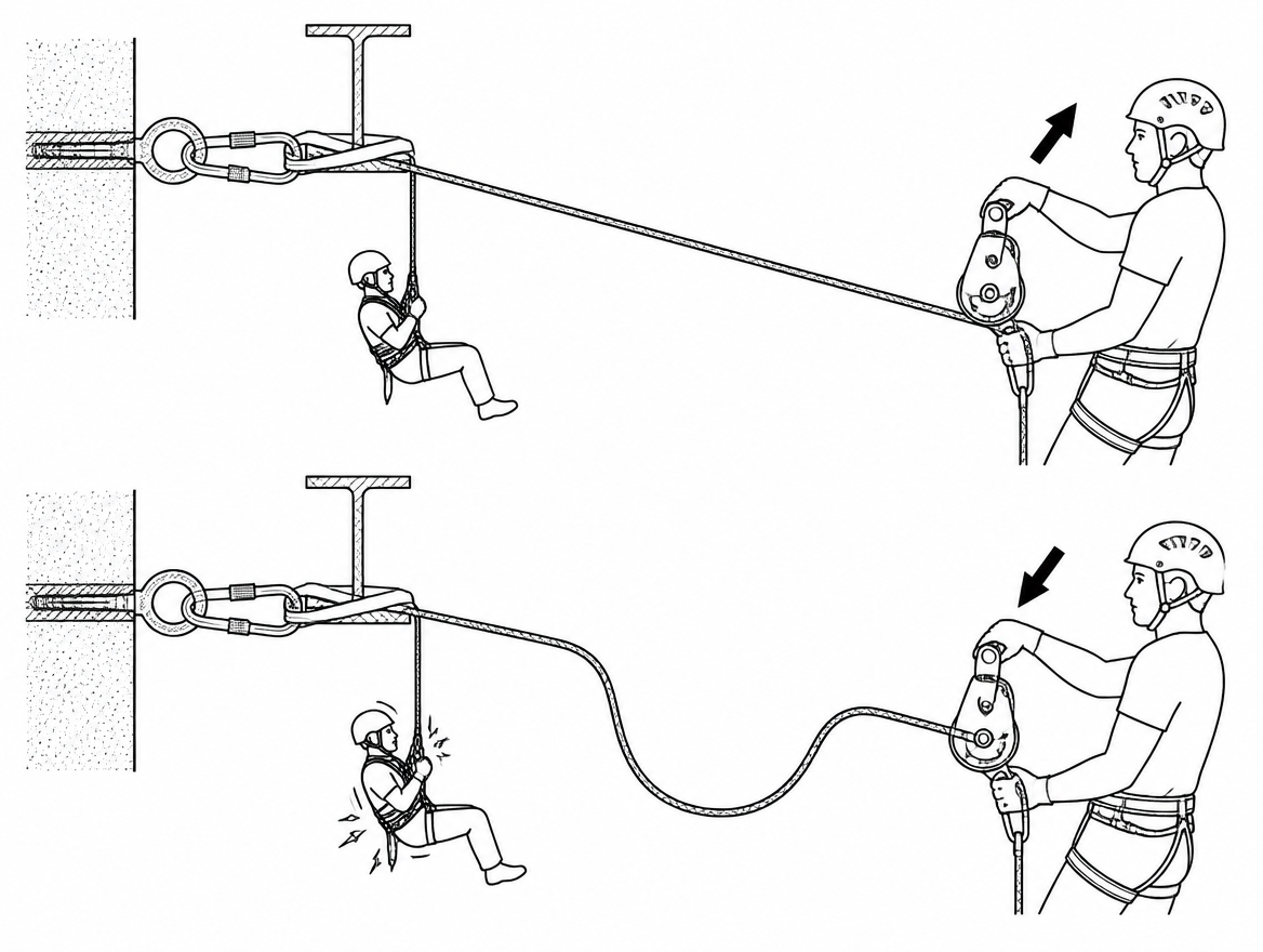
Catching a fall and converting it to a controlled lower
If the main line fails or the hauling system runs away, the sequence is short and it is the reason the winch-descender is on the belay line in the first place:
- Hold. The brake hand grips the brake strand and the cam engages. Nothing else happens until the load is static and the team has confirmed it.
- Assess. The load is now on a single line and a single anchor. The operator confirms the device, connector and anchor are undamaged and correctly aligned, and that the load path is clear to the intended landing.
- Communicate. The belay operator states that the load is held and that the line is becoming the lowering line. The main-line team stands clear of the failed system and does not attempt to re-tension it into the belay.
- Lower. The handle is opened progressively, with the brake hand controlling rate on the brake strand. Rate is governed by the descent limits stated for the device under EN 341 – both the rated load and the maximum descent height – because a device within its load rating can still be outside its energy rating on a long lower.
- Land and secure. The load is landed onto structure or a stretcher stand and taken off the rope before the device is unrigged.
Post-incident, both the failed main-line components and the belay device are quarantined pending examination by a competent person. A device that has arrested a dynamic load has, by definition, been loaded outside normal working conditions and its continued use is a decision for the periodic examination process, not for the team on site.
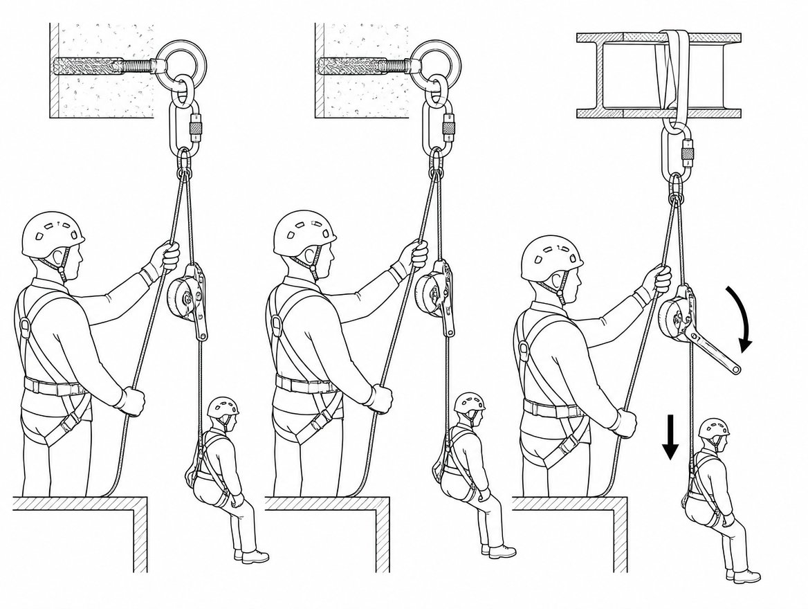
Errors that degrade the belay
- Rope threaded in reverse. The device becomes a low-friction redirect. Detected only by the loaded function test.
- Riding the handle. The most common operational error, and invisible in photographs of otherwise correct systems.
- Cross-loaded or gate-loaded connector. The device is pulled sideways at the anchor and loads the connector across its minor axis, where its rated strength does not apply.
- Device pinned against structure. A device that cannot rotate to align with the load direction may not release cleanly when the handle is opened.
- Wrong rope diameter. Below range, the rope slips; above range, the handle may not produce controlled movement.
- Slack allowed to build during transitions. Converts a redundancy into a shock-loading mechanism.
- Belay anchored to the same point as the main line where an independent anchor was available. A single anchor failure then takes both lines.
- Anti-panic treated as the brake. It arrests handle over-rotation; it does not manage rate, and it does not permit an unattended brake strand.
- No stopper knot and insufficient rope for a full lower. The conversion to lowering is then limited by rope length, not by the situation.
Commands, roles and hand positions
Two-line systems fail at the interface between the haul team and the belay operator. A single, pre-agreed command set – briefed before the system is loaded, and used by everyone including any casualty attendant – removes the ambiguity. Commands are short, name the recipient, and are acknowledged before movement starts or stops. Whistle or radio signals are agreed for situations where speech will not carry over plant noise.
Roles are named before the load goes on: one person on the belay device brake strand, one person calling the raise, and one person watching the edge and both rope paths. The belay operator does not double as the edge attendant. Rescue arrangements, competence requirements and the command protocol belong in the documented rescue plan; organisations operating an ISO 45001 management system will hold these under operational planning and control, and the plan is only as good as the last time the team rehearsed it against a real load.
Where the work is rope access, the fundamental principles and code of practice in EN ISO 22846-1 and EN ISO 22846-2 govern the working line and safety line arrangement, supervision and team composition.
Pre-use checks, periodic examination and records
EN 365 sets out the general requirements for instructions for use, maintenance, periodic examination, repair and marking of personal fall protection equipment, including periodic examination by a competent person at intervals of at least 12 months, with the outcome recorded. For a winch-descender used as a belay device, the pre-use check covers:
- Device body and side plate: cracks, deformation, sharp edges, wear grooves in the rope channel or on the cam.
- Cam and axles: free movement, full return to the braking position, no play beyond what the instructions permit.
- Handle and anti-panic mechanism: full travel, correct sequence, no binding.
- Brake surfaces: no glazing, no aluminium transfer or embedded grit, no wear beyond the manufacturer’s stated limit.
- Connector: gate closes and locks fully, no burrs, no wear on the bearing surface.
- Rope: sheath integrity along the whole working length, no glazing, contamination or core damage; diameter within the device’s stated range.
- Function test on the rope actually installed, under load, before the load goes on.
Contamination is the check most often skipped. Cement dust, drilling slurry and hydraulic oil all change the friction characteristics of a self-braking device, and the effect is not reliably visible.
Practical takeaway
A winch-descender earns its place on the belay line because it can hold and then lower without a changeover. It keeps that value only when three things are true every time the system is built: the rope is threaded in the correct direction and proven by a loaded function test, the release handle is left alone while the load is being raised, and slack is kept to a visible minimum and removed only while the load is static. The device’s rated load, descent limits and rope diameter range come from its own instructions under EN 341 and EN 12841 and are not transferable between models.
Next step: read the instructions for use for the specific device on the anchor alongside the periodic examination record, and confirm that the rope on the reel is EN 1891 Type A within the stated diameter range before the next two-line raise is rigged.
Frequently asked questions
Can a winch-descender replace a Type A backup device on a personal safety line?
No. In EN-standards rope access work, a person on personal ropes uses a working line with a descender or ascender and a separate safety line fitted with a Type A backup device to EN 12841. A winch-descender is not a Type A backup device and does not substitute for one. Its belay role belongs to load lines operated by a team, such as raising or lowering a stretcher, rescue frame or casualty on a two-line system, confined space entry and retrieval, or lowering plant, tooling or a suspended load where a secondary line must remain operable under load.
Is a winch-descender certified to arrest a free fall?
A certification for arresting a free fall is almost never printed on a device of this type. There is no EN product standard that certifies a winch-descender as a fall-arrest component in the sense of EN 363 fall-arrest systems, and none of the usual certifications (EN 341, EN 12841 Type C, EN 1496, EN 12278) imply an energy-absorbing function. Its ability to hold a suddenly applied load is a manufacturer-declared performance characteristic, not a harmonised requirement, and the figures differ between models.
Where do I find the authoritative load figures for my specific device?
In the instructions for use supplied with the device under EN 365. Figures such as maximum rated load, maximum load for two-person or rescue use, and declared slip or peak-force behaviour differ between models, and the instructions are the only authoritative source for the specific device on the anchor.
Why is slack control so important on the belay line?
Because the system's protection against high arrest forces comes from keeping the fall factor near zero, not from the device. EN 1891 Type A low-stretch kernmantle rope, which is the correct rope for these systems, absorbs very little energy by design. Slack in the belay line is the single largest variable the operator controls, so it is kept to a small visible curve with the brake strand controlled by hand.
What rope, connector and anchor requirements apply?
Rope: EN 1891 Type A low-stretch kernmantle within the exact diameter range marked on the device and stated in its instructions — many devices in this class are specified for 10.5–11.5 mm. A rope below the stated range slips in the brake mechanism; a rope above it binds and can defeat the release handle. Glazed, fused or heavily contaminated sheath alters friction unpredictably. Connectors are EN 362 screw-gate or automatic locking, sized so the device sits in the long axis and cannot ride up onto the gate. Anchor devices to EN 795 are selected for the anticipated load, including a two-person rescue load where that applies, and the belay line is rigged to an anchor independent of the main line where reasonably practicable. A stopper knot goes in the tail, with enough rope to complete a full lower, plus edge protection or a deviation on both lines.
Need this as a document you can issue? The template library gives you the risk assessments, permits and inspection logs in editable form — and employer plans cover a whole team with completion records.