Safety / Tips and Tricks / Rope access and confined space
Activity 01 · Rope access
How to Calculate Mechanical Advantage: Strand Counting, the T-Method and Real Anchor Loads
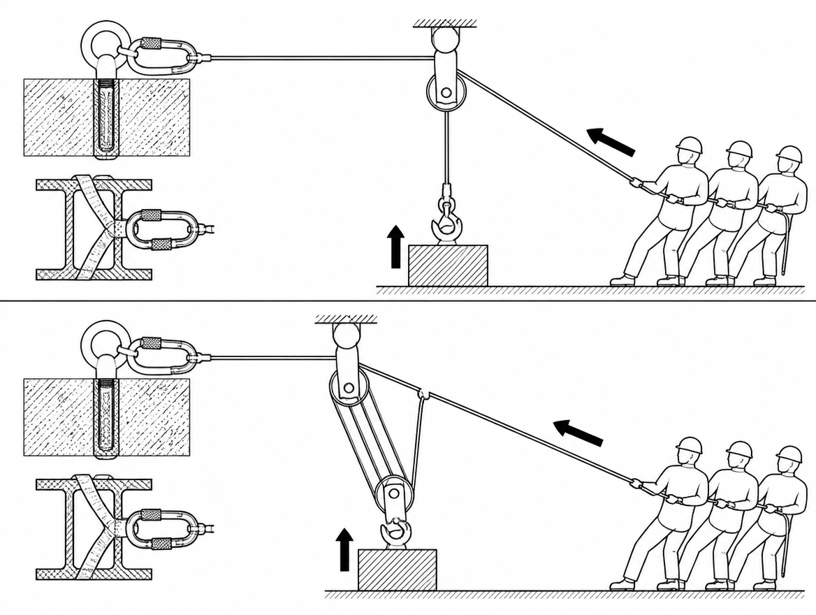
A mechanical advantage calculation answers two separate questions, and only one of them is about pulling. The first is whether the crew on the haul line can move the load at all. The second — the one that gets skipped — is how much force the anchor, the pulleys, the slings and the rope will actually see while that happens. A team that miscounts a system by one strand may plan for 4:1 and rig 2:1, or plan for a 6 kN anchor load and generate 10 kN. Both errors are arithmetic, and both are avoidable on paper before anything is loaded.
This article covers the three methods that matter on site: counting strands for simple systems, the T-method for anything more complicated, and the friction correction that turns a theoretical ratio into the number the haul team will actually feel. It also covers what the result tells you about anchor loading, and where the relevant EN standards fit.
Theoretical mechanical advantage and actual mechanical advantage
Mechanical advantage (MA) is the ratio between the force applied to the load and the force applied by the operator or haul team.
- Theoretical mechanical advantage (TMA) assumes frictionless sheaves, perfectly parallel strands and no rope stiffness. It is a geometry calculation and it is always the number you start from.
- Actual mechanical advantage (AMA) is TMA reduced by friction at every sheave, every rope-on-rope contact and every edge the rope crosses. It is always lower than TMA, and the gap widens with every additional sheave.
Both are written as ratios in the form MA:1. A 4:1 system means 1 kN of haul force produces 4 kN at the load in theory. Rig the same 4:1 on carabiners instead of pulleys and the load may see barely half of that.
Counting strands: the fast method for simple systems
In a simple system — one rope, one set of pulleys, all moving pulleys travelling toward the anchor at the same speed — TMA equals the number of rope strands pulling on the load.
The reliable version of the rule is: count the strands attached to, or running to, the travelling part of the system, including the strand you are pulling on if it also runs to the travelling part. Strands running to the anchor do not count. A pulley fixed to the anchor changes the direction of pull and adds no mechanical advantage at all; it only adds friction.
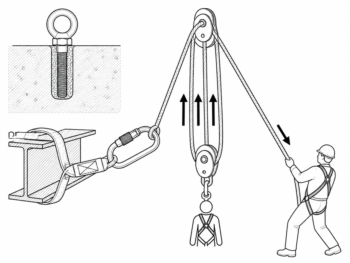
Three configurations that are routinely miscounted
- Change of direction mistaken for advantage. Rope from the load, over a pulley at the anchor, to the haul team: one strand pulls on the load. That is 1:1, no matter how much easier the direction feels.
- 2:1 with the pulley on the load. Rope end fixed to the anchor, down through a pulley attached to the load, back up to the haul team: two strands support the load. That is 2:1.
- A grab in the wrong place. In a Z-rig, moving the travelling rope grab so that it sits on the wrong side of a strand converts a 3:1 into a 1:1 with extra friction. The hardware looks identical; only the rope path differs.
The T-method: one procedure that works for every system
Strand counting fails as soon as a system becomes compound (one system hauling on another) or complex (pulleys travelling in more than one direction, or at different speeds). The T-method — tracking units of tension through the rope path — works for all of them and takes under a minute with a pen.
- Assign 1 unit of tension (1 T) to the strand the haul team pulls.
- Follow that strand. Rope passing over a frictionless pulley carries the same tension on both sides, so the strand leaving the pulley also carries 1 T.
- Each pulley’s attachment point carries the sum of the tensions in the strands passing over it (near-parallel strands; angled strands need vector addition).
- Where a rope grab or a knot transfers force into another rope, add the tension it delivers to the tension already in that rope.
- Add every tension arriving at the load. That total is the TMA.
For compound systems there is a shortcut: multiply the stages. A 2:1 hauling on a 3:1 gives 2 × 3 = 6:1. A 3:1 hauling on a 3:1 gives 9:1. Always verify a compound system with the T-method before trusting the multiplication, because the stages must genuinely be in series.
Worked example: standard Z-rig
Rope path: end tied to the load, up to a travelling rope grab, on to a pulley at the anchor, back toward the load through a travelling pulley hanging from that grab, then out to the haul team.
- Haul strand: 1 T.
- Over the travelling pulley, the strand running to the anchor pulley: 1 T.
- Over the anchor pulley, the strand running back to the grab: 1 T.
- The travelling pulley therefore carries 1 + 1 = 2 T, delivered into the load-side rope through the grab.
- Load-side rope tension = 1 T (rope continuing through the grab) + 2 T (from the pulley) = 3 T.
TMA = 3:1. A 300 kg load (about 2.94 kN) needs roughly 0.98 kN of frictionless haul force.
Worked example: 2:1 hauling on a 3:1
Rig a separate 2:1 (rope anchored, through a pulley on the haul strand of the Z-rig) and haul on that instead of on the Z-rig directly. Each unit of tension the crew applies arrives at the Z-rig haul strand as 2 T; the Z-rig then multiplies by three. TMA = 6:1. The same 2.94 kN load now needs about 0.49 kN — but the rope now travels six metres for every metre the load moves.
Adding friction: from TMA to AMA
Apply an efficiency factor η at each sheave. Tension drops in the direction of rope travel, so the strand leaving a sheave carries η × the tension entering it. Recalculate the T-method with those reduced values.
Use the efficiency your manufacturer publishes for the specific pulley and rope diameter. The values below are typical published ranges for illustration, not requirements set by any standard:
| Sheave arrangement | Typical efficiency |
|---|---|
| Sealed ball-bearing rescue/rigging pulley, correct rope diameter | ~95% |
| Bushing or plain-bearing pulley | ~85–90% |
| Undersized sheave with stiff, large-diameter rope | lower again; check the data sheet |
| Rope running directly over a locked carabiner | ~50–60% |
| Rope over a beam, edge or another rope | not quantifiable — eliminate it, don’t model it |
Z-rig on two 95% pulleys. Haul strand 1 T → travelling pulley → 0.95 T → anchor pulley → 0.90 T. Travelling pulley carries 1 + 0.95 = 1.95 T. Force at the load = 0.90 + 1.95 = ≈2.85:1.
The same Z-rig on carabiners at 55%. Haul strand 1 T → 0.55 T → 0.30 T. Travelling carabiner carries 1 + 0.55 = 1.55 T. Force at the load = 0.30 + 1.55 = ≈1.85:1. The system that was rigged as a 3:1 delivers less than a 2:1, and the crew has no way of knowing except by calculating it.
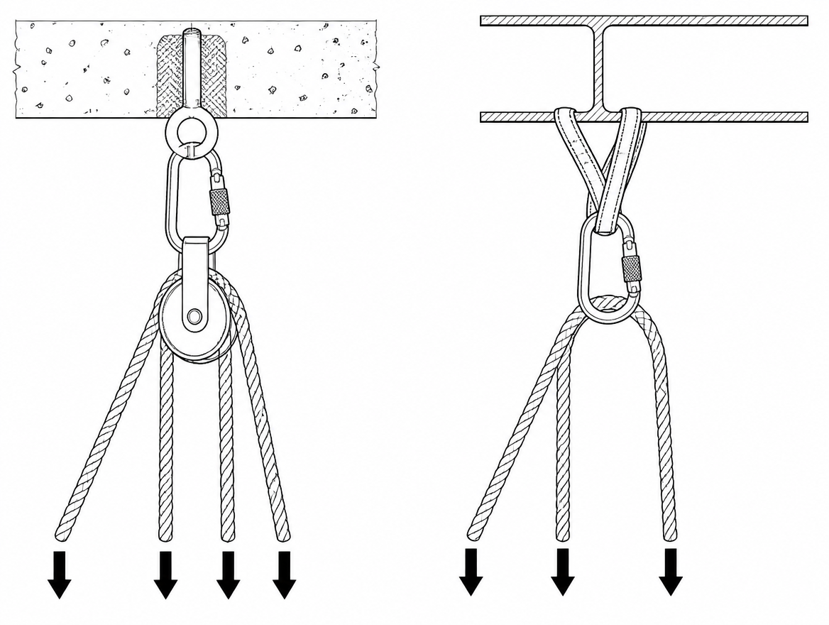
EN 12278 sets safety requirements and test methods for pulleys used in mountaineering and rope work, including strength testing; efficiency figures are published by manufacturers on that basis and vary by sheave diameter, bearing type and rope. Take them from the product documentation for the hardware in the kit, not from a generic figure.
Anchor load is not the same as the load
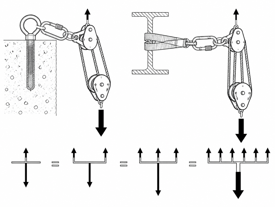
This is the part of the calculation with consequences for anchor selection. The anchor does not see the load; it sees the sum of the tensions in the strands attached to it, and that total changes between the hauling phase and the holding phase.
In the ideal 3:1 above, with the load at 3 T:
- While hauling: the anchor pulley carries the two strands passing over it, 1 + 1 = 2 T. The haul team’s feet carry the remaining 1 T.
- When the crew rests and the progress-capture device takes the load: the anchor carries the full load, 3 T.
- If the haul line is redirected back past the anchor for a better pulling position, that redirect adds its own resultant to the same anchor — and the resultant depends on the angle between the strands, not just their tensions.
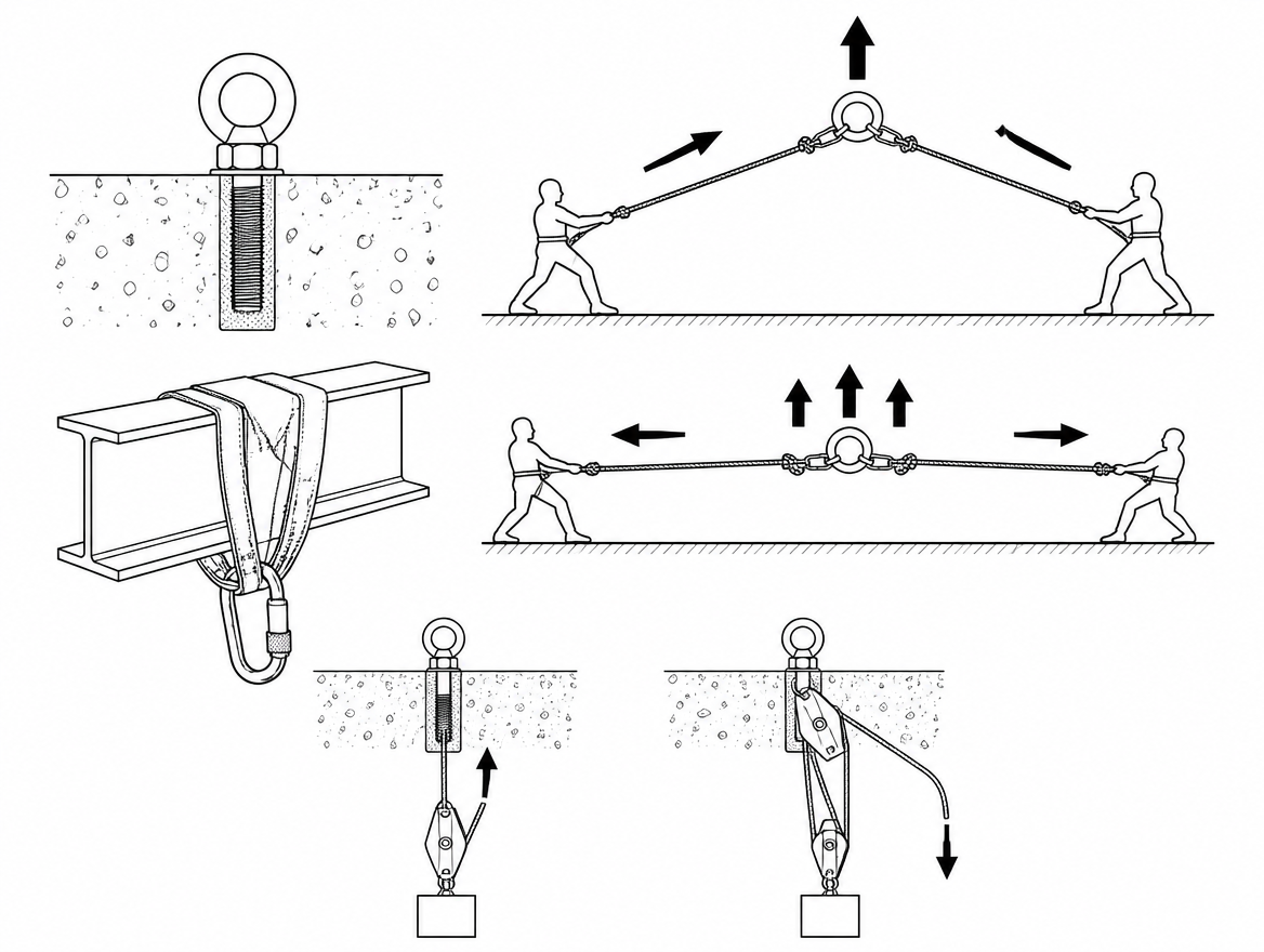
Two strands leaving a pulley at a narrow included angle produce a resultant close to the sum of their tensions. Open the angle toward 120° and the resultant falls toward the tension in a single strand. The same geometry rule governs multi-leg slings, where the working load limit assigned under EN 1492-1 (flat woven webbing slings), EN 1492-2 (roundslings), EN 13414-1 (steel wire rope slings) or EN 818-4 (grade 8 chain slings) is stated for defined angle ranges. Anchor devices themselves fall under EN 795, and the calculated worst-case anchor force — the holding phase, not the hauling phase — is the figure the anchor and its structure have to accommodate.
Levers, lever hoists and winches
Not every mechanical advantage calculation involves rope strands.
Levers and bars
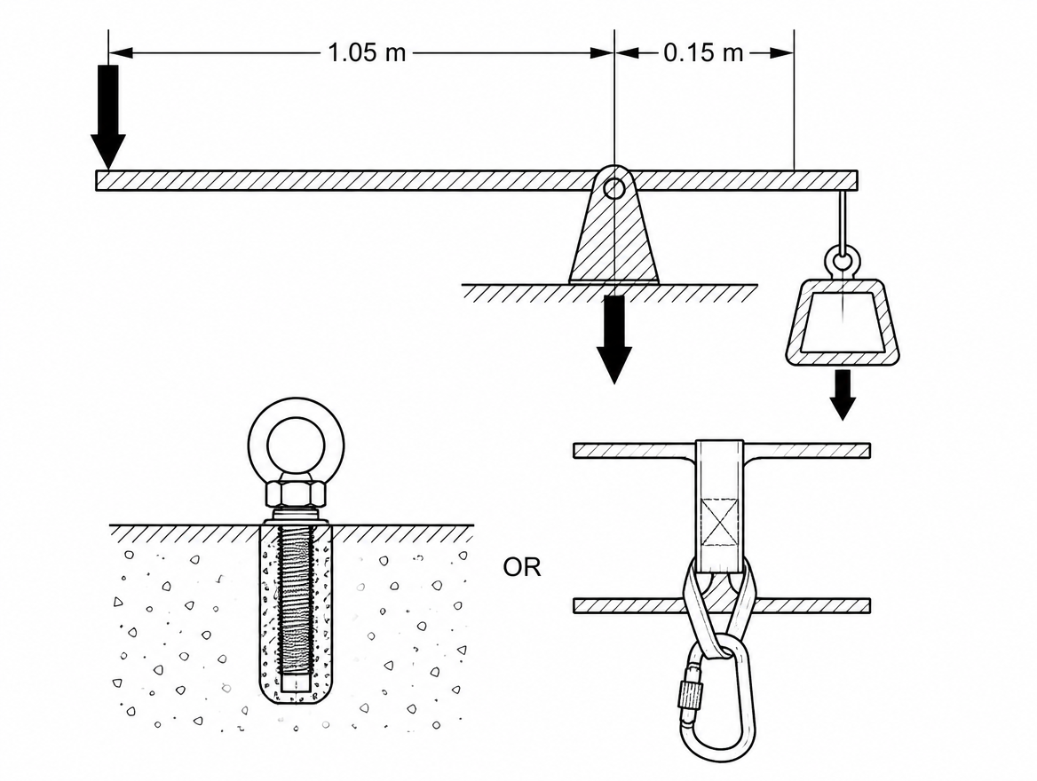
For a first-class lever, MA = effort arm ÷ load arm, both measured from the fulcrum. A 1.20 m bar with the fulcrum 0.15 m from the load gives an effort arm of 1.05 m and a load arm of 0.15 m: MA = 7:1. The fulcrum then carries effort plus load — roughly 8 units for every 1 unit applied — which is why the fulcrum block, not the bar, is usually what fails or shifts.
Lever hoists, chain blocks and winches
In geared equipment the mechanical advantage is built in by the manufacturer through gear reduction and the number of chain or rope falls, and it is already accounted for in the marked working load limit. Do not recalculate it and do not extend the lever: hand-powered cranes and hoists are designed and rated to EN 13157, power-driven winches and hoists to EN 14492-1 and EN 14492-2, and lifting accessories and machinery placed on the EU market carry marked ratings under Directive 2006/42/EC. Adding a cheater bar to a lever hoist increases the applied force beyond the design assumption without changing the rating.
One winch-specific point that does belong in a calculation: on a multi-layer drum, the available line pull is highest on the first layer and decreases as the effective drum radius grows with each layer wound on. Check the manufacturer’s line-pull-per-layer data before assuming the rated pull is available at the outer layer.
The trade-off: distance, speed and rope length
Mechanical advantage costs travel. Rope pulled through the system = MA × distance the load moves. A 6:1 moving a load 5 m requires 30 m of rope travel and a reset area to match. Higher MA also means more sheaves, more friction, more rope in the system and therefore more stretch to take up before the load starts moving. Beyond roughly 4:1 to 6:1, the practical answer on many sites is a second stage or a powered device rather than more strands.
Field checklist for a mechanical advantage calculation
- Sketch the actual rope path, including every rope grab and redirect.
- Classify the system: simple, compound or complex.
- Calculate TMA — strand count for simple systems, T-method for everything else.
- Apply the manufacturer’s efficiency figure at each sheave and recalculate to get AMA.
- Calculate the haul force required for the actual load, and check it against what the available crew or device can deliver.
- Calculate the anchor force in both the hauling and the holding phase, including any redirect, and take the higher figure.
- Compare every calculated force against the marked WLL or rated force of each component in that force path — pulleys, connectors, slings, anchor device.
- Calculate rope travel (MA × load travel) and confirm rope length and reset space.
Documenting these figures for each standard rigging configuration used on site — rather than recalculating under pressure — fits directly into the hazard identification and operational control requirements of an occupational health and safety management system to ISO 45001, and into the machinery risk assessment approach of EN ISO 12100 where the system forms part of a work equipment set-up.
Next step
Take the two or three haul or rigging configurations your teams actually build, run the T-method on each, and record TMA, AMA at the pulleys in your kit, required haul force at the maximum planned load, and worst-case anchor force. Then check those anchor figures against the rated capacity of the anchor devices in use to EN 795 and against the WLL marked on the slings and connectors in the load path. A configuration whose numbers are already on paper is one that can be checked by a supervisor in seconds instead of argued about at the edge.
Frequently asked questions
What is the difference between theoretical and actual mechanical advantage?
Theoretical mechanical advantage (TMA) is a pure geometry calculation that assumes frictionless sheaves, perfectly parallel strands and no rope stiffness, and it is always the number you start from. Actual mechanical advantage (AMA) is TMA reduced by friction at every sheave, every rope-on-rope contact and every edge the rope crosses. AMA is always lower than TMA, and the gap widens with every additional sheave.
How do I count strands to work out mechanical advantage?
In a simple system — one rope, one set of pulleys, all moving pulleys travelling toward the anchor at the same speed — TMA equals the number of rope strands pulling on the load. Count the strands attached to, or running to, the travelling part of the system, including the strand you are pulling on if it also runs to the travelling part. Strands running to the anchor do not count: a pulley fixed to the anchor only changes the direction of pull, adds no mechanical advantage at all, and only adds friction.
When does strand counting stop working, and what should I use instead?
Strand counting fails as soon as a system becomes compound (one system hauling on another) or complex (pulleys travelling in more than one direction, or at different speeds). The T-method — tracking units of tension through the rope path — works for all of them and takes under a minute with a pen.
How does the T-method work step by step?
Assign 1 unit of tension (1 T) to the strand the haul team pulls and follow it. Rope passing over a frictionless pulley carries the same tension on both sides, so the strand leaving the pulley also carries 1 T. Each pulley's attachment point carries the sum of the tensions in the strands passing over it (for near-parallel strands; angled strands need vector addition). Where a rope grab or knot transfers force into another rope, add the tension it delivers to the tension already in that rope. Add every tension arriving at the load — that total is the TMA.
What mechanical advantage does a 2:1 hauling on a 3:1 give, and what is the trade-off?
For compound systems the stages multiply, so a 2:1 hauling on a 3:1 gives 6:1 (and a 3:1 on a 3:1 gives 9:1). A 2.94 kN load (about 300 kg) that needs roughly 0.98 kN of frictionless haul force on a 3:1 needs about 0.49 kN on the 6:1 — but the rope now travels six metres for every metre the load moves. Always verify a compound system with the T-method before trusting the multiplication, because the stages must genuinely be in series.
Need this as a document you can issue? The template library gives you the risk assessments, permits and inspection logs in editable form — and employer plans cover a whole team with completion records.