Safety / Tips and Tricks / Rope access and confined space
Activity 01 · Rope access
Lanyard-End Connector for Fall Arrest: Gate Opening, Roll-Out and Correct Loading
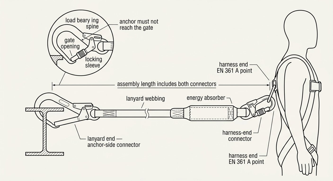
On a fall-arrest lanyard, the connector at the anchor end does more work than any other component in the assembly. It is the part that gets clipped and unclipped dozens of times a shift, the part that has to fit whatever structural member is actually available on site, and the part most likely to be defeated by geometry rather than by lack of strength. A connector rated well above the loads a fall arrest can generate will still fail if the anchor it is clipped to can reach the gate. This note covers how to select the lanyard-end connector, how to load it, and what to check before clipping in.
What “lanyard-end” means in a fall-arrest assembly
A typical energy-absorbing lanyard has two ends and two very different connectors:
- Harness end. A small connector — often a captive-eye karabiner or a connector permanently sewn into the absorber’s termination — attached to a fall-arrest attachment point on an EN 361 full body harness: the dorsal or sternal A point, never a work-positioning belt ring.
- Lanyard (anchor) end. The connector that goes onto the structure or anchor device. This is the one that must be selected for the anchor, not for the lanyard.
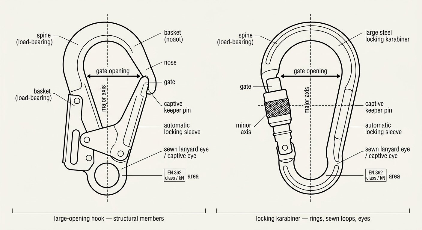
Both are covered by EN 362, the standard for fall-protection connectors, which groups them into classes — including Class B (basic connector), Class A (anchor connector, intended for a specific type of anchor), Class M (multi-use, loadable on major and minor axis), Class T (terminating connector, intended for one loading direction within a subsystem) and Class Q (screw-link). The class letter is marked on the connector body alongside the rated strength in kN. For the anchor end of a fall-arrest lanyard the practical choice is usually between a large-opening hook (commonly declared as an anchor or basic connector, depending on the manufacturer’s stated intended anchor) and a large steel or aluminium locking karabiner.
The three things the anchor-side connector must fit
1. Gate opening versus the actual anchor
The gate opening is the limiting dimension. A standard karabiner opening will take a rigging ring, a sewn anchor loop or a small eyebolt, but not a scaffold tube with a fitting on it, not a rolled steel beam flange, and not a rebar cage. Large-opening “scaffold” hooks exist precisely so that the connector can be closed around structural members without needing a separate sling. Before ordering lanyards for a job, establish what the anchors will physically be — tube, flange, cast-in eye, rail, textile sling — and pick the opening from that.
2. Geometry: can the anchor reach the gate?
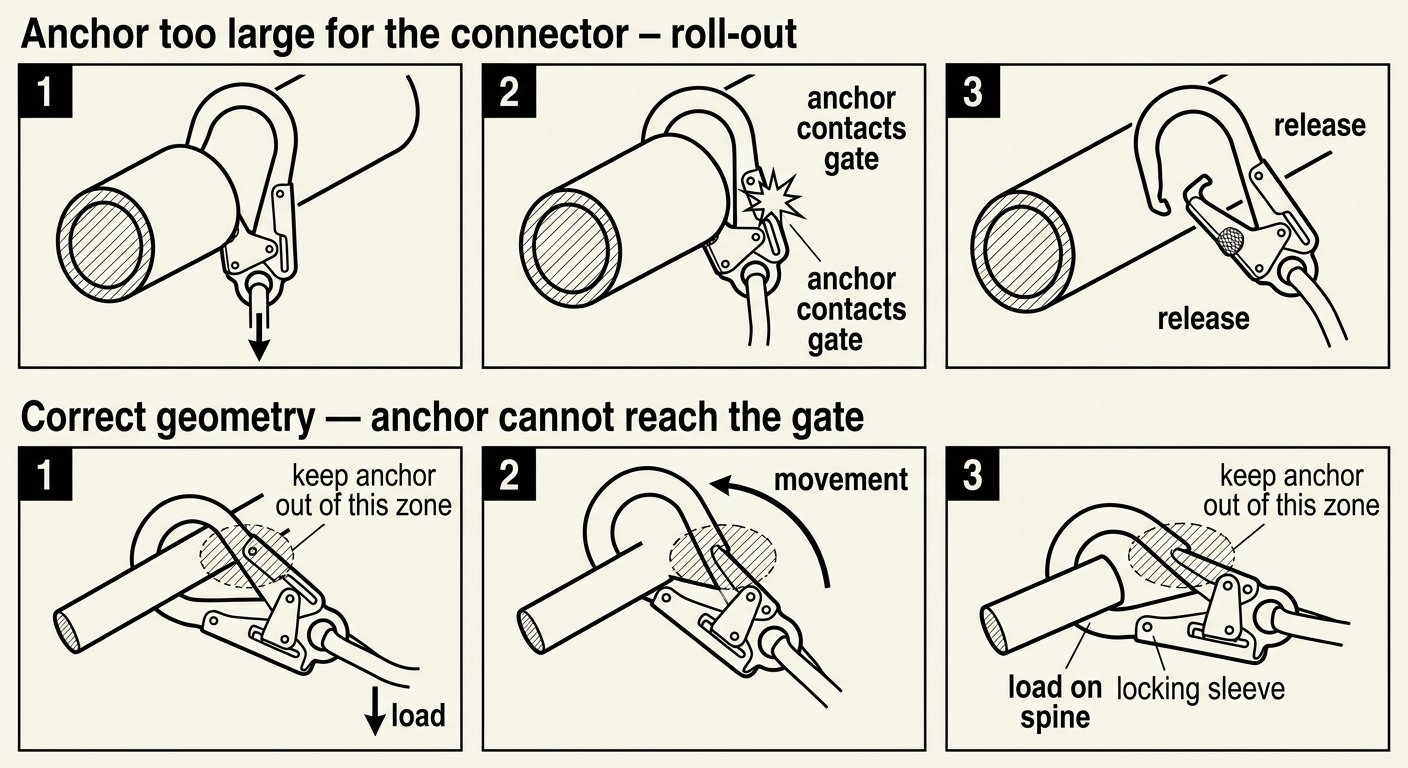
Fitting around the anchor is not enough. Once loaded, the connector should sit with the anchor bearing on the spine or basket of the connector, well away from the gate. If the anchor is large enough in diameter to sit against the gate, or if the connector can be levered over a corner or edge, the assembly is unsafe regardless of the marked strength.
3. Material and strength rating
Steel hooks resist the abrasion of repeated clipping onto scaffold tube and structural steel and are usually the default for construction fall arrest; aluminium saves weight, which matters on long lanyards worn all shift, but wears faster against hard steel edges. Whichever is chosen, the marked rating must be legible — that marking is what lets a supervisor or EHS reviewer confirm the connector is a certified fall-arrest component and not a hardware-store hook or a general-purpose lifting fitting.
Roll-out: the failure mode that defines gate opening
Roll-out is the sequence in which a hook, under load or under movement, rotates against an anchor that is too large for it, forces the gate open from the inside or the side, and releases. It does not require a defect in the connector. It requires only a mismatch between the size of the anchor and the geometry of the hook, plus movement — which a fall provides in abundance.
The practical rule is that the anchor must be small enough, relative to the connector, that under load it cannot contact the gate. The corollary is that oversizing a hook is not automatically safer: an unnecessarily large opening on a small-diameter anchor gives the anchor room to travel toward the gate. Match the connector to the anchor rather than reaching for the biggest hook on the rack.
Features that reduce roll-out risk include a captive keeper or captive-pin nose (so the anchor cannot slip between nose and gate), a double-action locking gate that requires two distinct movements to open, and a deep basket that keeps the load seated on the spine. A repeatable pre-clip check is worth building into the routine — the method in checking connector compatibility before you clip in is exactly the sequence this decision needs.
Loading the connector: major axis, gate closed, gate locked
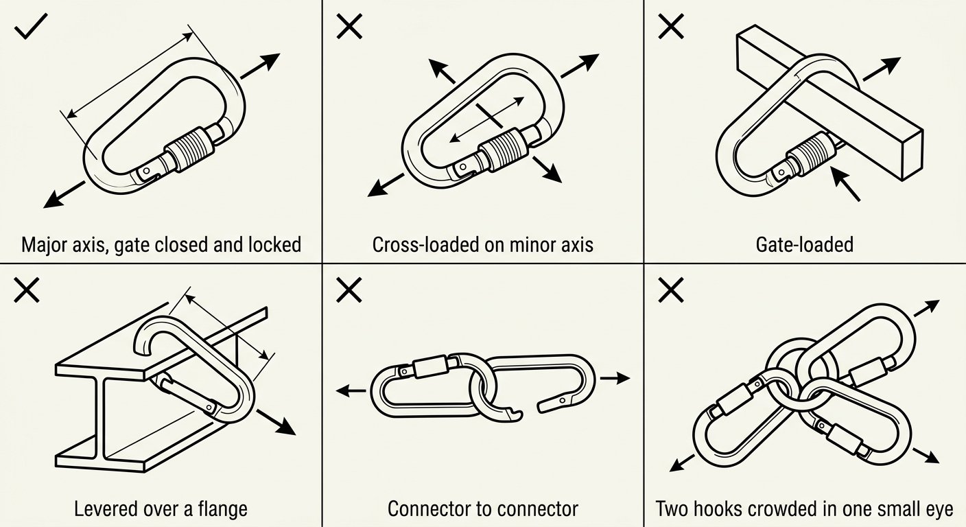
Fall-arrest connectors are designed and tested primarily along the major axis — spine to gate, in line with the load. Every other loading condition is weaker, and some are dramatically weaker:
- Cross-loading / minor-axis loading: load applied across the connector rather than along it. Only connectors specifically declared for multi-axis use are intended for this.
- Gate loading: the anchor or an obstruction bearing directly on the gate or locking sleeve. The gate is not a load-bearing member.
- Levered / three-point loading: the connector bridged across a beam flange, bracket or corner so that the structure pries the body open.
- Connector-to-connector: two hooks clipped into each other, or two lanyard hooks crowded into one small anchor eye, so that neither can align with the load.
In practice, most of this is controlled by how the connector is oriented at the moment of clipping. Clip so the gate faces away from the structure and the spine takes the load; make sure the locking sleeve or collar is fully home, not resting mid-travel; and where the lanyard can swing, think about where the connector will end up if the worker moves to the far end of the work zone. The background on axes and gate behaviour is set out in connector basics: gates, axes and loading.
Locking mechanism: screw-lock or automatic
EN 362 requires locking connectors for fall arrest, and it directs that a connector which will be opened more than once during a work shift should be self-closing and self-locking. That effectively rules screw-gates out for the anchor end of a lanyard used for repeated moves: a manual sleeve that has to be threaded shut each time will eventually be left unthreaded. Twist-lock and push-twist automatic gates are the norm for scaffold hooks and for anchor-end karabiners on twin-leg lanyards.
Screw-locks retain a role where a connection is made once and stays made for the duration of the task — a lanyard left rigged to a fixed anchor, for example. The trade-offs between mechanisms are compared in connector locking systems compared: screw-lock, two-stage and three-stage auto-lock.
Length, mass and clearance
The connector is part of the lanyard’s length, not an addition to it. An energy-absorbing lanyard certified to EN 355 has a maximum assembly length of 2 m measured with the absorber, the lanyard and both connectors in place — which is why substituting a longer hook or adding an extra karabiner “to make it reach” can put the assembly outside its certification and lengthen the free fall. If reach is the problem, the answer is a different anchor position or a different subsystem, not an added link.
Connector mass matters for two reasons. A heavy steel hook on a slack lanyard swings, and a swinging hook near the worker’s head or near a colleague is a hazard in its own right. It also loads the harness attachment or parking point when the leg is not in use. Where the anchor allows it, a lighter connector with the correct geometry is preferable to a heavier one with excess opening.
Finally, the anchor-end connector affects required clearance below the work position, because everything from anchor to harness attachment contributes to fall distance. Selecting the connector and calculating clearance are the same decision, not two separate ones. Lanyard type drives this as well — see which type of fall-arrest lanyard to choose.
Parking the unused leg of a twin-leg lanyard
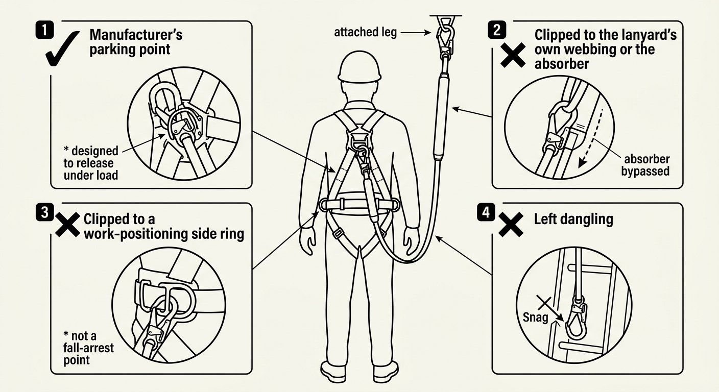
Twin-leg lanyards are used so that one leg is always attached while the other is moved. That means one heavy hook is always spare, and where it gets parked matters:
- Correct: the parking points provided by the manufacturer on the harness or on the absorber housing — typically designed to release under load, so that a fall on the attached leg does not transmit force through the harness webbing or through the parked leg.
- Incorrect: clipped back onto the lanyard’s own webbing or onto the energy absorber. A fall then loads the absorber through the wrong path and it may not deploy as designed.
- Incorrect: clipped to a work-positioning side ring on an EN 358 belt. Those rings are not fall-arrest attachment points, and using them as parking points blurs a distinction that should stay sharp.
- Incorrect: left dangling. A free hook catches on structure, on ladder rungs and on other workers’ equipment.
Pre-use check on the anchor-end connector
The lanyard-end connector takes more mechanical abuse than the rest of the assembly, so it deserves a specific look rather than a general glance:
- Gate action: gate closes fully and briskly under spring force with no help, from any position.
- Lock action: the sleeve or collar returns and fully engages every time; no grit, no partial travel, no need to nudge it home.
- Nose and keeper: the nose engagement is clean and undamaged; on captive-pin designs, the pin and slot are not worn or bent.
- Body: no deformation, no gate that no longer aligns with the nose, no gap between nose and closed gate. Gate misalignment is a common sign of past overload or of being dropped from height.
- Wear and corrosion: abrasion grooves at the load-bearing point, sharp edges raised by contact with structural steel, pitting, or paint loss with rust beneath on steel hooks.
- Markings: standard, class and rating still legible. An unreadable connector cannot be verified and should be withdrawn.
- History: anything that has arrested a fall or been shock-loaded is withdrawn from service with the rest of the assembly, whether or not damage is visible.
Shape also carries information about intended use, and mixing the two ends up is a recurring error — the reasoning is set out in connector shapes and where each belongs.
Don’t reuse fall-arrest reasoning on a positioning lanyard
The anchor-side connector on a work-positioning lanyard looks similar and is chosen on different grounds: it is loaded more or less continuously, in tension against the belt, and the questions about opening size and roll-out come out differently. That case is treated separately in lanyard-end connector for work positioning.
Takeaway: select the anchor-end connector from the anchor it will actually be clipped to, confirm the anchor cannot reach the gate under load, keep the load on the major axis, and treat the connector’s length as part of the lanyard’s certified length. For the rest of this series, see the rope access and confined space technique notes.
Frequently asked questions
Can a standard locking karabiner be used as the lanyard-end connector for fall arrest?
Yes, provided the anchor it will be clipped to actually fits inside the gate opening and the anchor cannot bear against the gate once loaded. Karabiners are appropriate for rings, sewn anchor loops and eyes; they are not appropriate for scaffold tube with fittings, beam flanges or rebar, where a large-opening hook is needed instead.
Is a bigger gate opening always safer?
No. An oversized hook on a small-diameter anchor leaves the anchor free to travel out of the basket toward the gate, which is the condition that leads to roll-out. The connector should be matched to the intended anchor so that the load stays seated on the spine.
Can a screw-gate connector be used on the anchor end of a fall-arrest lanyard?
Only where the connection is made once and left in place for the task. EN 362 directs that a connector opened more than once during a work shift should be self-closing and self-locking, so repeated re-anchoring calls for a twist-lock or other automatic gate rather than a manual sleeve.
Does adding an extra karabiner to make the lanyard reach the anchor cause a problem?
Yes. An energy-absorbing lanyard is certified as a complete assembly with a maximum length that includes the absorber, the lanyard and both connectors, so adding a link lengthens the free fall and takes the assembly outside its certification. If reach is the problem, change the anchor position or the subsystem instead.
Where should the unused leg of a twin-leg lanyard be clipped?
To the parking point provided by the manufacturer on the harness or absorber housing, which is typically designed to release under load. It should never be clipped back onto the lanyard's own webbing or the energy absorber, since that changes the force path if a fall occurs on the attached leg.
What makes a lanyard-end connector unfit for further use?
A gate that does not close fully and briskly under spring force, a locking sleeve that does not fully engage every time, a gate no longer aligned with the nose, deformation, deep abrasion or corrosion at the load-bearing point, or markings that are no longer legible. Anything that has arrested a fall or been shock-loaded is withdrawn along with the rest of the assembly.
Need this as a document you can issue? The template library gives you the risk assessments, permits and inspection logs in editable form — and employer plans cover a whole team with completion records.