Safety / Tips and Tricks / Rope access and confined space
Activity 01 · Rope access
Lanyard-End Connector for Work Positioning: Choosing and Loading the Anchor-Side Hook
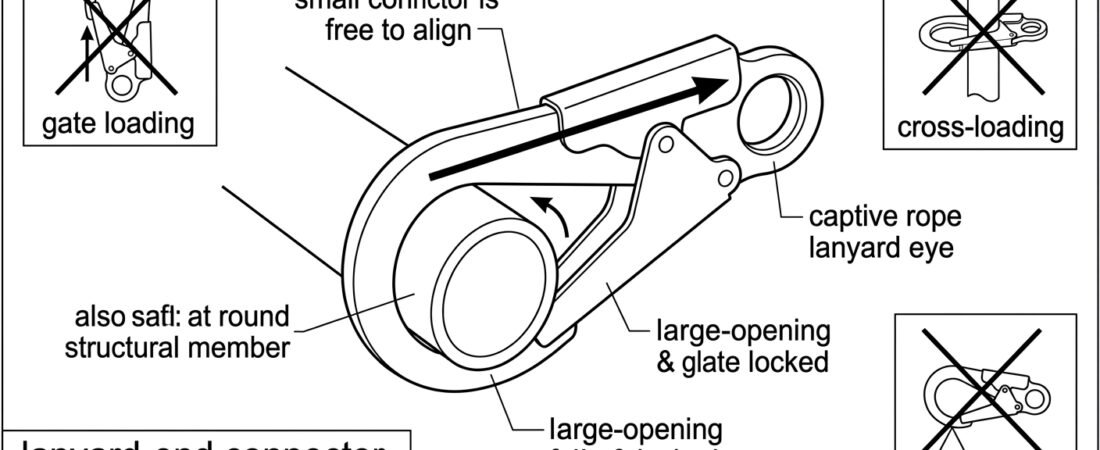
On an adjustable work positioning lanyard, the connector at the far end — the one that goes around the column, rung, pipe or scaffold tube — is the part of the system handled most and inspected least. It is opened and closed dozens of times a shift, frequently one-handed, frequently at arm's length and out of clear sight, and it is the single component that decides whether the lanyard stays where the worker put it when the belt is loaded and the body leans back. Choosing it badly, or clipping it into a position where it is loaded across the gate, is one of the more common avoidable faults on positioning work.
This note covers what the lanyard-end connector has to do, how to size and load it, and what to check before weight goes onto the lanyard.
Which connector this note is about
A work positioning lanyard has two ends and, in most designs, an adjuster somewhere between them:
- Harness end. Attaches to the lateral (side) attachment points of a work positioning belt or of the belt component of a harness, as covered by EN 358 for work positioning and restraint belts. On most lanyards this end is either fixed by a captive connector or terminated with a connector that is intended to stay put once rigged.
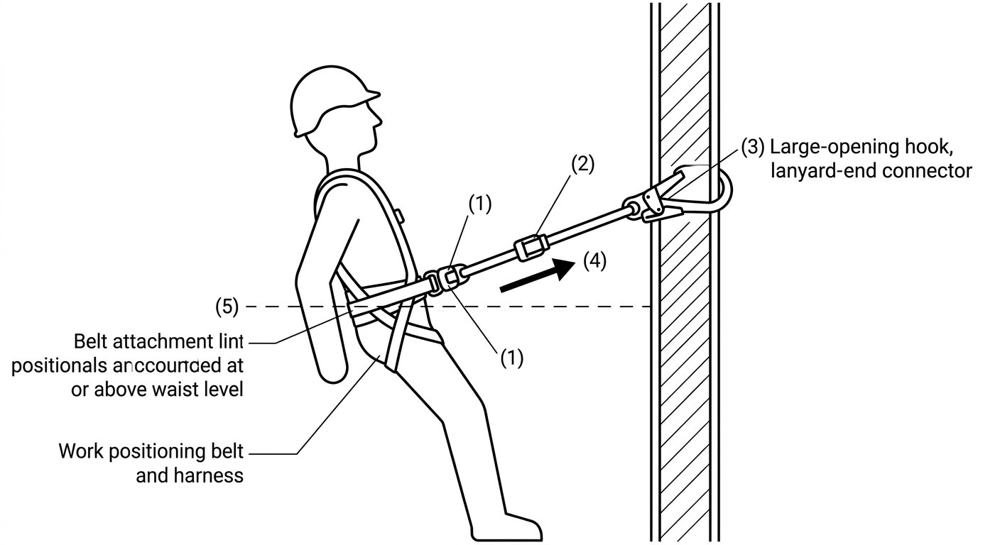
- Lanyard end (anchor side). Passes around the structure or clips to an anchor point. This is the working end — the one manipulated every time the operator repositions.
The two ends have genuinely different requirements. The harness end wants to be small, kept aligned, and left alone. The lanyard end wants a wide opening, a reliable self-closing action, and enough body strength and abrasion tolerance to be dragged around structural steel. Whichever connector is fitted, it must be a connector for fall protection conforming to EN 362 (or the equivalent local requirement), not a general-purpose hook or a load-rated lifting fitting.
What the lanyard end actually has to do
Four demands drive the choice:
- Pass around the members you actually work on. Scaffold tube, ladder rungs, tower legs, small-bore pipework and rolled steel sections all have different diameters and profiles. A gate opening that will not accept the member is useless; the operator will improvise, usually by choking a sling around the member or by clipping into something weaker.
- Close and lock without being watched. Positioning work involves clipping blind. A self-closing, self-locking gate removes the step most often skipped.
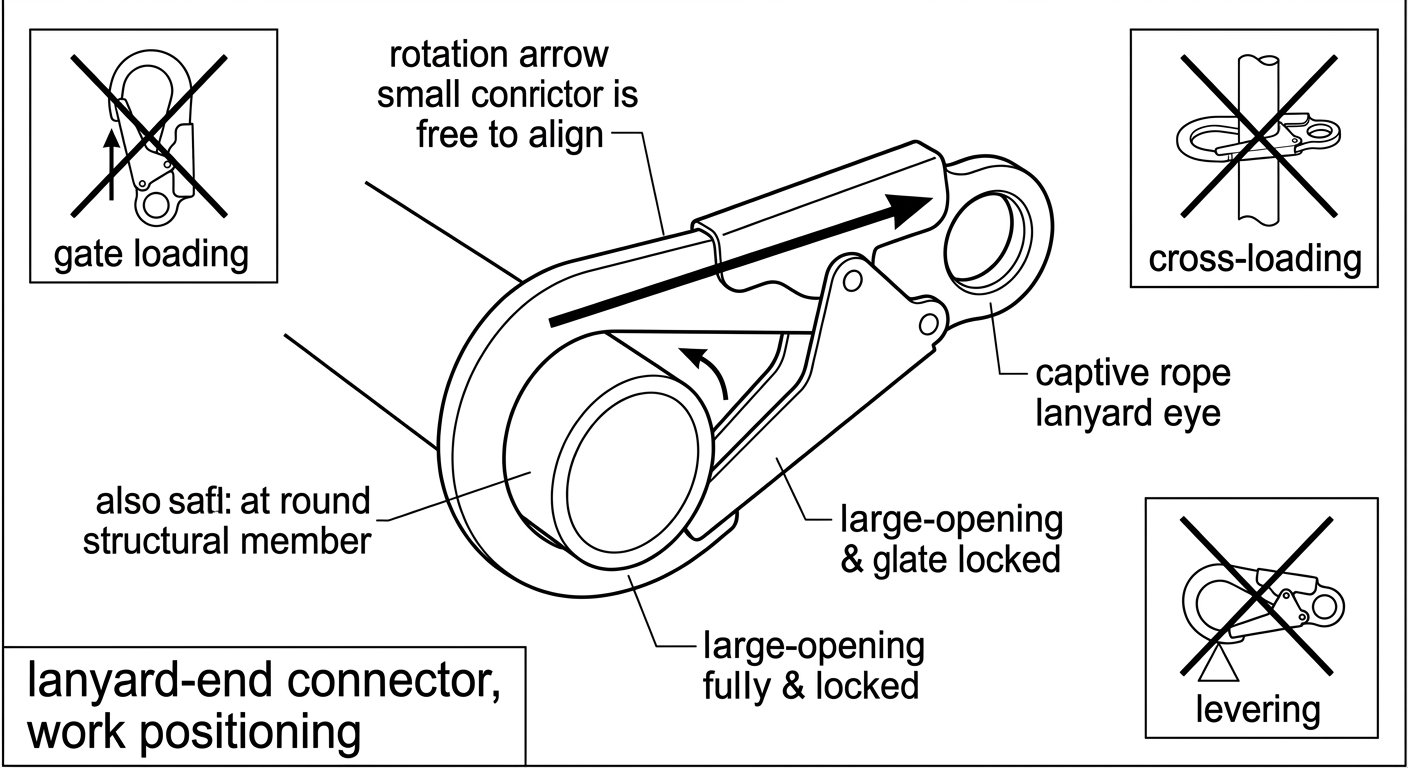
- Stay aligned under load. A tensioned positioning lanyard pulls in one direction, but that direction changes as the operator shifts weight or works around a corner. The connector needs to be free to rotate into line rather than being trapped against the structure.
- Take abrasion. Continuous contact with mill scale, weld spatter, concrete and grit wears connector bodies and, more importantly, wears the lanyard termination sitting inside them.
Sizing the gate opening: as large as necessary, no larger
Large-opening connectors — scaffold hooks, pole hooks and rebar hooks — exist because structural members are bigger than a standard karabiner will accept. But opening size is a trade-off, not a virtue on its own:
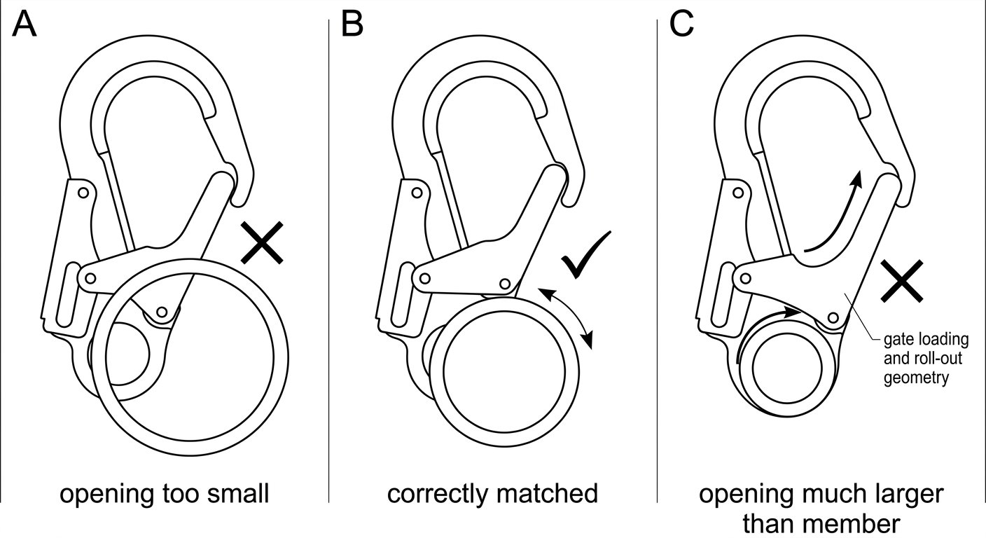
- Too small for the member: the connector cannot be used as intended, and the operator substitutes something less suitable.
- Correctly matched: the member sits in the back of the basket, the gate closes clear of it, and the connector can rotate to align with the load.
- Much larger than the member: the connector can shift, rotate and ride up toward the gate. On a slack lanyard it can work its way into a position where the gate is loaded, or where the nose and gate straddle the member — the geometry behind roll-out.
The practical rule is to carry the smallest opening that will genuinely accept the members on that structure, and to check the actual profile rather than assuming. A hook that fits a round tube may not close cleanly around the flange of a beam or over a wide handrail. Different body shapes suit different jobs; the trade-offs are set out in more detail in the note on connector shapes and where each belongs.
Loading: keep it on the major axis
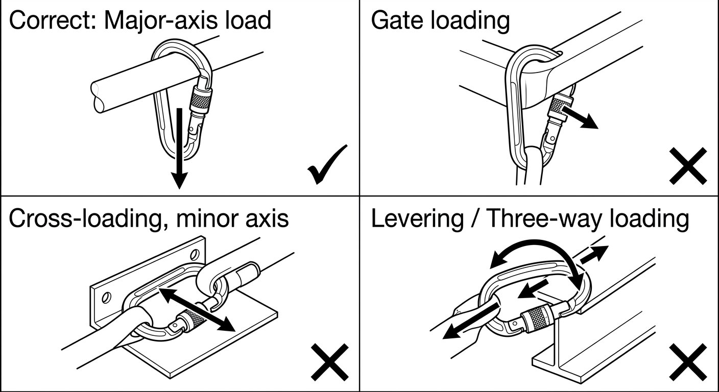
Connectors are strongest loaded along the major axis with the gate closed and locked. Every other loading case is weaker, in some cases substantially so, and the manufacturer’s marked strengths for minor-axis and open-gate loading are always lower than the major-axis figure. Three failure geometries recur on positioning work:
- Gate loading. The member bears against the gate rather than the spine. Usually caused by the connector being pulled sideways as the operator moves around the structure, or by an oversized opening letting the member migrate forward.
- Cross-loading (minor axis). The connector is loaded across its width, typically because it is trapped flat against a plate or wedged between two members and cannot rotate.
- Levering / three-way loading. The connector body bridges an edge, a flange or a rung so that load is applied as a bending moment across the spine and gate rather than as tension along the spine. Large-bodied hooks on narrow members are particularly prone to this.
The counter-measure is positional, not procedural: place the connector where it has room to hang and rotate freely, and re-check it after any significant change of working position. The underlying mechanics are covered in connector basics: gates, axes and loading.
Locking mechanism and one-handed use
Because the lanyard end is handled constantly, the locking system matters more here than almost anywhere else in a positioning system:
- Self-closing, self-locking gates are the normal choice. There is no separate action to forget, and the connector is locked from the moment it is released.
- Screw-lock (manual) sleeves are workable where a connector is rigged once and left, but they are a poor fit for a connector opened repeatedly at height: the sleeve can be left unscrewed, and vibration or contact with the structure can back it off.
- Two-stage versus three-stage actions are a trade between speed and resistance to inadvertent opening. Three-stage actions are harder to open accidentally against a structure but slower and less comfortable to work one-handed with gloves; two-stage actions are quicker but rely more on the gate geometry to prevent snagging open.
The comparison in connector locking systems compared: screw-lock, two-stage and three-stage auto-lock sets out how each behaves in practice. Whichever is chosen, glove compatibility should be tested with the gloves actually worn on the job — a locking action that cannot be worked in a rigger’s glove will be defeated sooner or later.
Material, body form and the lanyard termination
- Steel bodies tolerate abrasive structural contact, grit and hot-work environments far better and are the usual choice for permanent industrial positioning kit. The penalty is weight, which is noticeable on a lanyard the operator carries all day.
- Aluminium alloy bodies are lighter and are common on climbing-intensive work, but they mark and wear faster against steel and should be inspected more critically for grooving and deformation.
- Bearing surface. Where the lanyard’s rope or webbing eye sits inside the connector, a wider, smoother bearing surface spreads the load and reduces wear on the termination. Sharp internal radii and worn grooves cut textiles.
- Captive termination. Where the design allows it, keeping the lanyard eye captive at the correct end of the connector prevents the eye from creeping onto the gate side, which is a common precursor to gate loading.
The pre-clip check
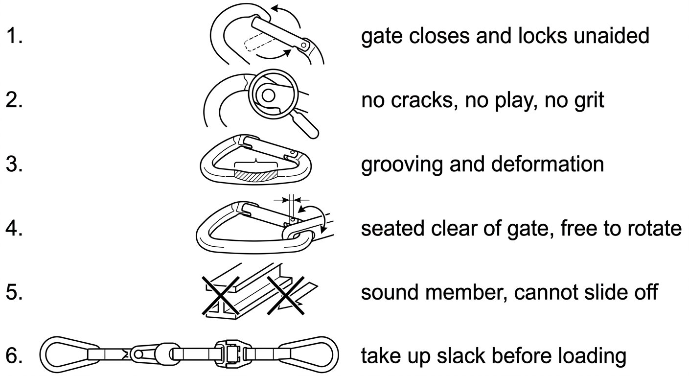
Before the lanyard is tensioned, run a short, repeatable check on the connector and the point it is on:
- Gate. Release it and let it snap shut on its own. It should close fully and lock without help. A gate that needs a nudge is a gate that will one day not close.
- Nose and hinge. No visible cracks, no play at the rivet, nothing packed with grit or paint.
- Body. No deep grooving at the bearing surfaces, no deformation of the basket, markings still legible.
- Seating. The member sits in the back of the basket, clear of the gate, and the connector hangs free enough to rotate into line with the anticipated load.
- The member itself. Sound, continuous, unable to let the connector slide off along its length, and free of sharp edges or hot surfaces that will bear on the lanyard.
- Slack. Take the adjuster in until the lanyard is tensioned and the belt is loaded. Slack is what allows a connector to migrate into a bad orientation.
A structured version of the same reasoning, applied to connector-to-anchor pairings generally, is set out in checking connector compatibility: a field method before you clip in.
Work positioning is not fall arrest
An EN 358 positioning system is designed to hold the operator in a working position with the lanyard under tension, at or above the level of the belt attachment points, where a free fall is prevented or where any possible fall is very short. It is not a fall-arrest system, and neither the belt nor the lanyard-end connector should be treated as one.
Where a genuine fall risk remains — work above an unprotected edge, a positioning point below waist level, a structure that could allow the operator to drop clear — a separate fall-arrest system is needed, connected to the sternal or dorsal attachment of a harness meeting EN 361 for full body harnesses, on its own anchor, with the required clearance below. The positioning lanyard then does what it is for: holding the working stance, hands-free.
Recurring errors
- Using an oversized scaffold hook on a small-diameter member because it is the one already on the belt.
- Leaving the lanyard slack, so the connector can rotate, ride forward or lever against an edge.
- Clipping the lanyard end back into itself, into the lanyard’s own webbing, or into a load-bearing sling in a way that traps the connector flat.
- Positioning below the belt attachment points, converting a positioning lanyard into a short-fall situation it was never designed for.
- Leaving a screw-lock sleeve unscrewed on a connector that is opened repeatedly.
- Ignoring wear at the bearing surface where the lanyard eye sits — the textile usually fails before the metal does.
Takeaway
Select the lanyard-end connector from the structure, not from the catalogue: the smallest opening that genuinely accepts the members on site, a self-closing and self-locking gate that can be worked with the gloves actually worn, a body material matched to the abrasion and heat present, and a termination kept captive at the spine end. Then rig it so it hangs free, loads along the spine, and stays tensioned. Everything else about a positioning lanyard is adjustment.
Related technique notes, including connector selection for descenders and lanyard type selection, are collected in the rope access and confined space technique notes.
Frequently asked questions
Can a standard karabiner be used as the lanyard-end connector on a work positioning lanyard?
Only if it will actually close around the members being used and is a locking connector intended for fall protection under EN 362. On most structural work the members are too large for a standard karabiner opening, which is why large-opening scaffold, pole and rebar hooks exist. The wrong-sized connector usually leads to improvised anchoring, which is the real hazard.
Why not simply carry the largest-opening hook available?
A gate opening much larger than the member lets the member shift and ride forward toward the nose and gate, especially when the lanyard is slack. That is the geometry behind gate loading and roll-out. Carry the smallest opening that genuinely accepts the members on that structure.
Is a screw-lock connector acceptable at the lanyard end?
It can be used where a connector is rigged once and left alone, but it is a poor choice for a connector opened repeatedly at height. The sleeve can be left unscrewed after a reposition, and contact with the structure or vibration can back it off. A self-closing, self-locking gate removes the step most often skipped.
Does the work positioning lanyard also protect against a fall?
No. A work positioning system under EN 358 is designed to hold the operator in a working position with the lanyard tensioned and the attachment points at or above waist level, where a free fall is prevented or extremely short. Where a real fall risk remains, a separate fall-arrest system on the sternal or dorsal attachment of an EN 361 harness is required, on its own anchor, with adequate clearance below.
Steel or aluminium for the lanyard-end connector?
Steel tolerates abrasive structural contact, grit and hot work far better and is the usual choice for industrial positioning kit, at the cost of weight. Aluminium alloy is lighter for climbing-intensive work but wears and marks faster against steel and should be inspected more critically for grooving and deformation.
What part of the connector wears out first in positioning use?
In practice the textile usually suffers before the metal does. The rope or webbing eye of the lanyard bears inside the connector, so a worn or grooved bearing surface will cut the termination. Inspect both the connector's internal surfaces and the lanyard eye sitting in them at each check.
Need this as a document you can issue? The template library gives you the risk assessments, permits and inspection logs in editable form — and employer plans cover a whole team with completion records.