Safety / Tips and Tricks / Rope access and confined space
Activity 01 · Rope access
Haul System with a Descender: Rigging, Limits and the Haul-to-Lower Conversion
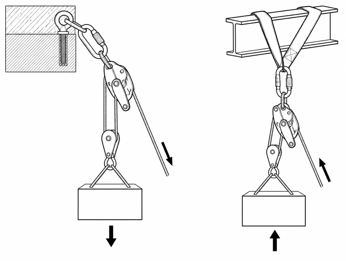
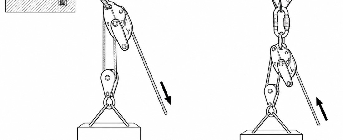
A self-braking descender rigged at the anchor is what allows one rope system to do two jobs: hold and lower a suspended load, then raise it again without being rebuilt. That matters most in the situations where rebuilding is least practical — a casualty hanging in a harness, a stuck rope access technician, or a load that has to come up over an edge and back down again. The descender holds the load hands-free between pulls, and the same handle that stops the raise starts a controlled lower. The trade-off is that a single small device is then acting as brake, progress capture and lowering control at once, and each of those roles has a different limit. This article covers how the system is rigged, which EN standards govern the parts, how much mechanical advantage actually reaches the load, and the checks that make the haul-to-lower conversion predictable.
What the descender contributes to a haul system
The devices in question are handled, self-braking descenders of the type certified for rope access and rescue work — typically to EN 12841 Type C (rope adjustment device for descent on the working line) and, in many cases, additionally to EN 341 (descender devices for rescue). In a haul configuration the device is anchored, the load line passes through it, and it performs three functions:
- Progress capture. The cam allows rope to be drawn through in the haul direction and locks when the load pulls back. The load is held between pulls without anyone touching the system.
- Controlled lowering. Opening the handle releases the cam progressively, so the same rig lowers without a changeover.
- A fixed braking point. Friction is generated at the anchor rather than on a body-worn device, which keeps the operator out of the load path.
Not every descender is suitable. A device without a self-braking cam (a simple figure-of-eight, a bar rack, a plain tube) provides no progress capture at all and cannot be used this way. Whether a given self-braking descender is approved for hauling is stated in its manufacturer’s instructions for use — some are explicitly permitted, some are not, and that declaration is not interchangeable between models.
Which standards apply to the components
A haul system is a personal fall protection assembly in the sense of EN 363: the parts have to be compatible with each other, not merely certified in isolation.
| Component | Primary standard | Practical point |
|---|---|---|
| Self-braking descender | EN 12841 Type C; often also EN 341 | EN 341:2011 classifies rescue descenders by the descent energy and descent heights they were tested for; the declared class and figures are in the instructions. |
| Load and haul rope | EN 1891 Type A low-stretch kernmantel | Diameter must fall inside the range declared for the device (commonly around 10.5–11.5 mm). Dynamic mountaineering rope is not a substitute. |
| Pulleys | EN 12278 | Sheave diameter and bearing type drive system efficiency; check the rope diameter range. |
| Rope clamp used as progress capture or haul grab | EN 567, or EN 12841 Type B | Toothed clamps are function-tested at modest loads and their instructions generally restrict them to single-person loading; they can damage a sheath if the load arrives suddenly. |
| Connectors | EN 362 | Locking, loaded on the major axis, gate closed and locked before the system is tensioned. |
| Anchor device | EN 795 (types A–E) | The anchor carries the load plus the haul force, not just the load. Structural anchors need to be verified for the resultant direction of pull. |
| Harness on the person being raised | EN 361 (with EN 358 or EN 813 as applicable) | Attachment point chosen for the task; suspension time is a clinical concern in its own right. |
EN 365 sets the framework for marking, instructions for use, records and periodic examination that applies across all of the above.
Rigging the system
Anchor and orientation
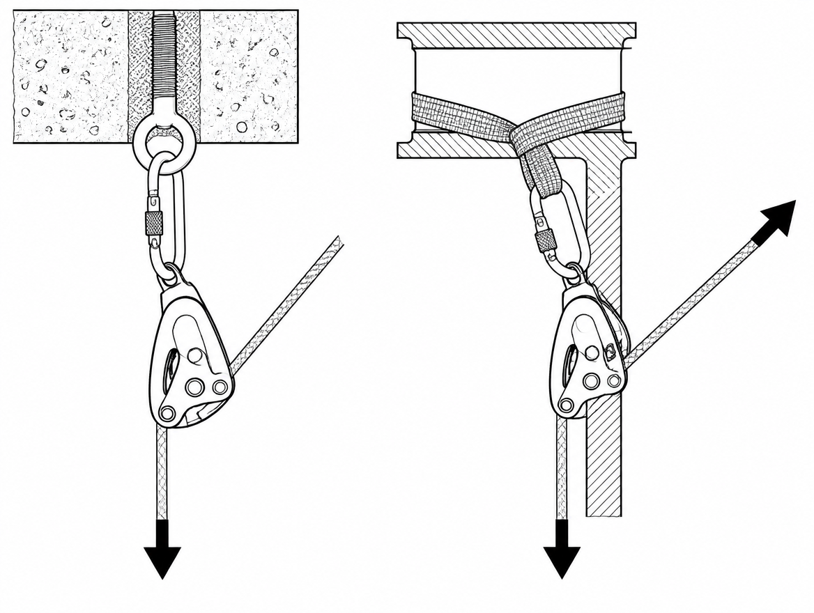
The descender hangs from the anchor on a locking connector to EN 362 and must be free to align itself with the direction of pull. If the body of the device is trapped against steelwork, a beam flange or a bag, the side plates can be cross-loaded and the cam prevented from rotating. Leave the device room to move, and keep the resultant of load line plus haul line in mind when choosing the anchor point.
Rope path through the device
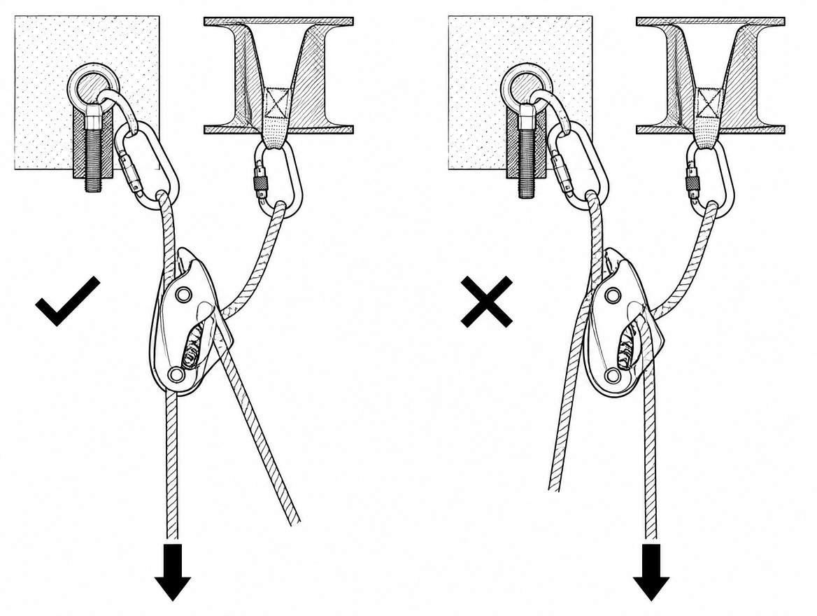
Self-braking descenders are directional. The load strand and the free (brake) strand are not interchangeable, and a device threaded backwards may feel as though it is functioning under a light test load while providing no reliable braking under a real one. Thread the rope as shown in the manufacturer’s diagram, close and lock the side plate, then run a function test: load the device lightly and confirm the cam grips, then confirm rope can be drawn through in the haul direction.
Progress capture
The descender’s cam is the primary progress capture. Many teams add a second capture — a purpose-built progress capture pulley or a rope clamp rated for the intended load — on the load strand above the descender, so that resetting the haul does not depend on a single cam and so that the haul can be reset while the load is held elsewhere. Where a toothed EN 567 clamp is used for this, keep it as a haul-side grab rather than the sole holder of a heavy or shock-prone load.
Mechanical advantage
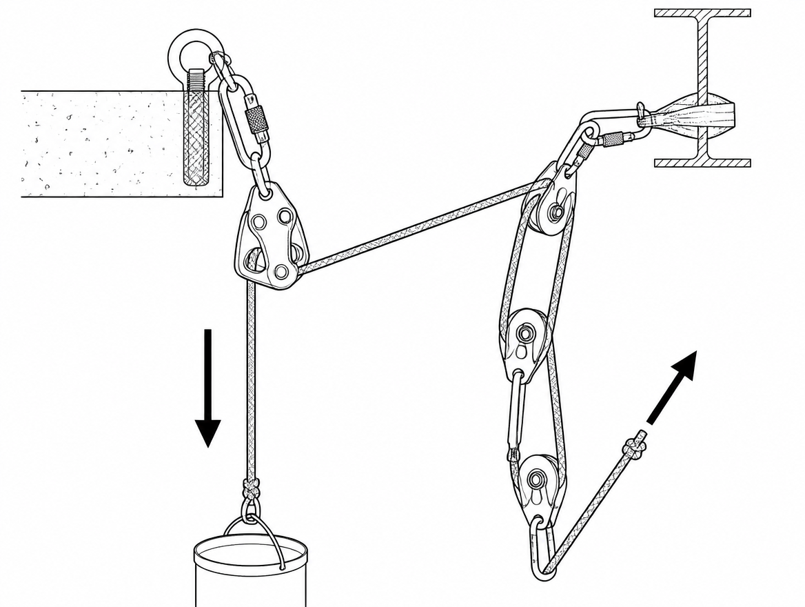
The descender only holds and lowers; the raise comes from whatever advantage is built onto the free strand. Common arrangements are a 2:1 with a single travelling pulley, a 3:1 Z-rig (one travelling pulley plus one directional at the anchor) or a 4:1 piggyback assembled separately and clipped on. The Z-rig is the usual starting point for a one- or two-person load with a small haul team, because it needs few components and resets quickly.
A backup line for the person being raised
Where a person is on the rope, standard rescue practice is a separate backup line on an independent anchor, managed with a device intended for that purpose — for rope access, an EN 12841 Type A device on the safety line. The haul system’s progress capture is not a fall arrest provision.
Real mechanical advantage: where the effort goes
A 3:1 on paper does not deliver 3:1 at the load. Every sheave costs efficiency: well-maintained ball-bearing pulleys to EN 12278 are commonly in the region of 90–95 % efficient, and plain-bushing sheaves considerably less. Drawing rope back through a loaded self-braking descender adds a further friction penalty that varies with rope diameter, rope condition, temperature and how squarely the strand enters the device. Rope running over an unprotected edge can add more resistance than the load itself.
Two practical consequences follow. First, keep the pull on the free strand roughly in line with the device so the cam is not being dragged sideways as it releases. Second, resistance is not the same as load: if the system suddenly feels heavy, the usual causes are an edge, a snagged strand, a jammed knot at the device or a second rope taking tension — not a heavier casualty. Adding haulers to overcome an unidentified obstruction is how anchors, ropes and rope clamps get loaded well beyond their intended working range, and how a suspended person gets crushed against a structure.
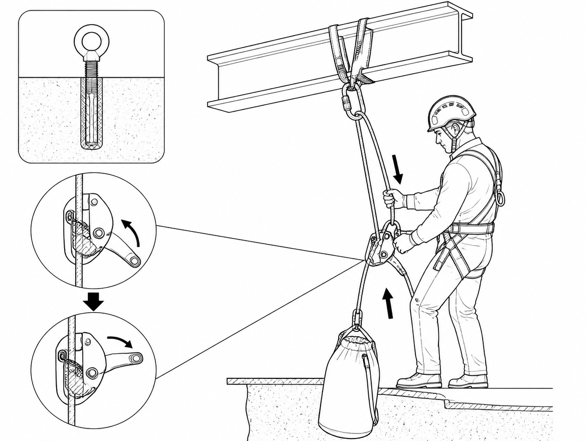
Converting from haul to lower
This is the manoeuvre the configuration exists for, and it is where the sequence matters most.
- Stop the haul and let the load settle onto the descender’s cam. Confirm visually that the cam is engaged and the load strand is tight into the device.
- Take the tension off any secondary progress capture on the load strand and remove or slacken it. A capture device left engaged will hold the load and the lower will not start; a capture device released under tension will drop the load onto the descender.
- Slacken and, where practical, strip the mechanical advantage off the free strand so the rope can run freely. Manage the tail into a rope bag — a tangled tail is the most common reason a lower has to be stopped mid-descent.
- Take the free strand in the brake hand, below the device, before touching the handle. Control comes from the hand on the rope; the handle only modulates how much the cam releases.
- Open the handle progressively and lower at a speed the team on the ground and the person on the rope can both work with. Watch the edge and the point where the load will transition.
- To stop, release the handle and let the cam re-engage, keeping the free strand controlled until the load is confirmed static.
Devices with an anti-panic function engage additional braking if the handle is pulled beyond its normal range. That function is a backup for a startled or overloaded operator, not a speed control, and it is defeated the moment the handle is held past its stop or the cam is gripped by hand. Neither the handle nor the cam should ever be tied, taped or blocked open.
Load limits: a one-person device under a two-person load
EN 12841 Type C devices are designed and tested around a single user plus equipment; a maximum rated load in the region of 150 kg is typical, but the figure that applies is the one in the manufacturer’s instructions for that model. A rescuer descending with a casualty, or a stretcher with an attendant, can approach or exceed that figure before any haul forces are added.
Where a two-person or rescue load is foreseeable, the questions to answer before the system is used in anger are: does the manufacturer declare a rescue or two-person load for this device and rope combination, does the rope diameter chosen still fall inside the declared range at that load, and does the anchor account for load plus haul force rather than load alone. If the answer to any of them is unknown, that is a planning problem to resolve off the job, not on it.
Failure modes that show up on site
- Rope threaded the wrong way through the descender, discovered only when the load is committed.
- Cam obstructed by a connector, a sling, a glove, a bag or the operator’s own hand, so it cannot rotate to lock.
- Rope diameter outside the declared range, or a stiff, glazed, dirty, wet or icy rope changing the friction the device generates.
- Side plate not fully closed and locked before loading.
- Knot or splice arriving at the device during a lower, with no plan for passing it.
- Secondary progress capture left engaged at the start of a lower, or released under tension.
- Haul strand pulled sharply off-axis, cross-loading the device against the structure.
- Free strand let go during a lower on the assumption the anti-panic function will handle it.
- Uncontrolled haul force: too many haulers on a 3:1 or 4:1 against an unidentified obstruction.
Pre-use checks and periodic examination
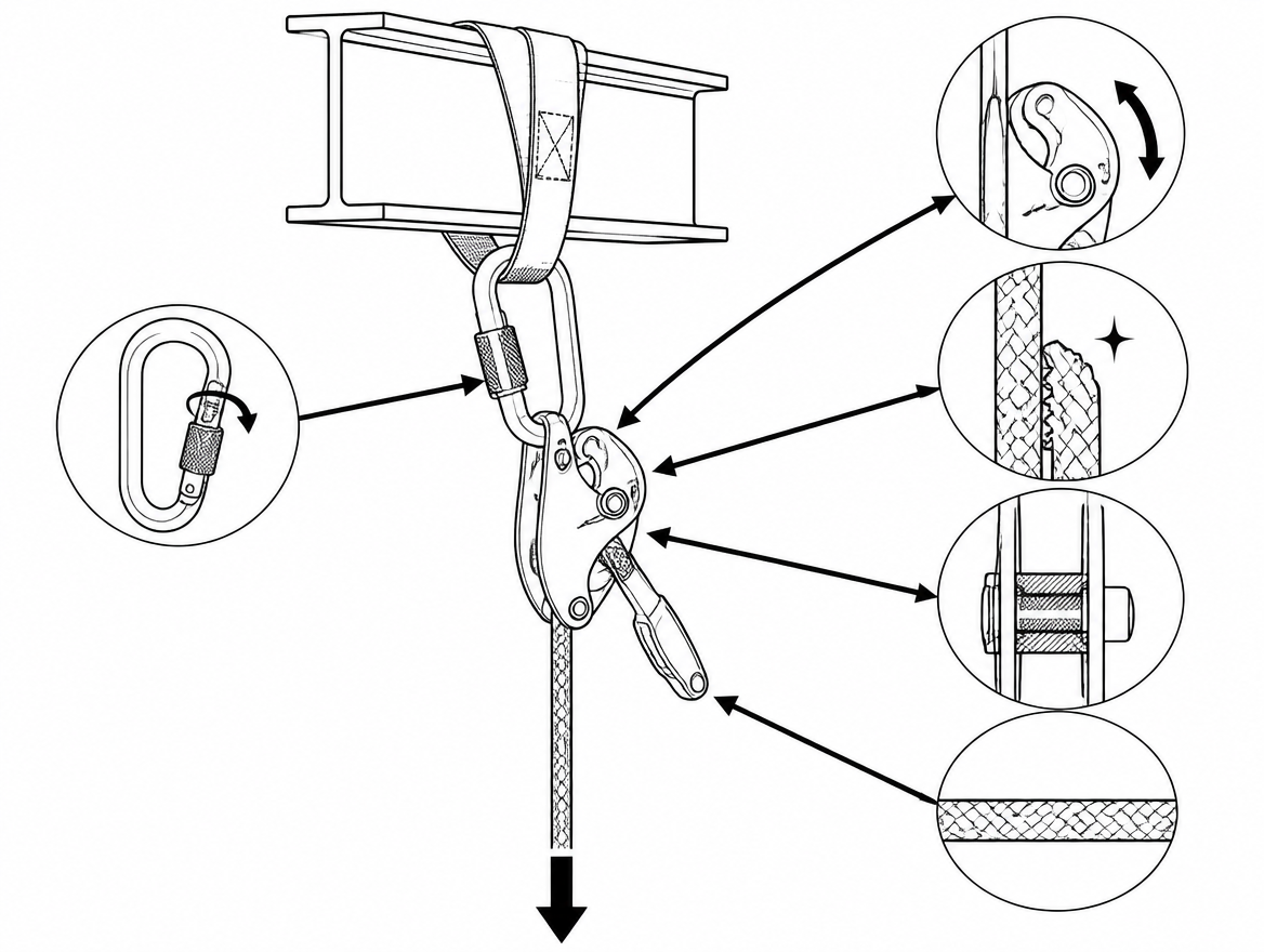
Before each use, with the rope installed and the system unloaded: check the cam rotates freely and returns, the teeth or gripping surface are clean and not clogged with grit or corrosion, the side plates are undeformed and the axle secure, the handle moves through its full travel and returns to the closed position, the anti-panic function is present and free, and the rope shows no glazing, flat spots, sheath damage or core deformity where it will run through the device. Connectors: gates closing fully, sleeves locking, no wear notch at the load-bearing point. Then load-test the assembled system with a light load, in a controlled position, before committing a person to it.
EN 365 requires periodic examination by a competent person at intervals determined by the manufacturer and use conditions, and at least every twelve months for PPE of this kind, with the results recorded. Descenders used in hauling see cam and sheave wear faster than descenders used only for descent, so use frequency and load are legitimate reasons for a shorter interval. Retire on the manufacturer’s criteria, not on appearance alone.
Roles, commands and planning
A haul system with a descender needs one person on the device and nobody else touching it. Assign the descender operator, an edge attendant with sight of the load and the rope where it crosses the edge, and a haul team leader who calls the pulls and the resets. Agree the command set before rigging — typically distinct calls for haul, stop, hold, slack and lower — and agree who has the authority to call a stop, which is anyone who sees a problem.
Under ISO 45001, this belongs in the emergency preparedness and response arrangements: the rescue method identified for each work-at-height task, the equipment held for it, the competence of the people expected to use it, and evidence that the system has been rehearsed with the actual anchors and edges involved. A haul-to-lower conversion practised for the first time during a real rescue takes far longer than the suspension tolerance of the person on the rope.
Takeaway
The value of building a haul system around a self-braking descender is the conversion: hold, raise, hold, lower, with no changeover and no hands in the load path. That value only holds if three things are settled in advance — that the specific device is declared by its manufacturer for hauling, that the rope diameter and total load stay inside the range the device was certified for under EN 12841 Type C (and EN 341 where claimed), and that the team can run the haul-to-lower sequence in order under pressure. The next step is a documentary one: pull the instructions for use for the exact descender, rope and progress capture in your kit, confirm the compatibility of that combination in writing, and rehearse the conversion on the anchors those items are actually deployed on.
Frequently asked questions
What three jobs does a self-braking descender do in a haul system?
Rigged at the anchor with the load line passing through it, the device provides progress capture (the cam lets rope be drawn through in the haul direction and locks when the load pulls back, holding the load hands-free between pulls), controlled lowering (opening the handle releases the cam progressively, so the same rig lowers without a changeover), and a fixed braking point, with friction generated at the anchor rather than on a body-worn device, keeping the operator out of the load path.
Can any descender be used for hauling?
No. A device without a self-braking cam — a simple figure-of-eight, a bar rack or a plain tube — provides no progress capture at all and cannot be used this way. Whether a given self-braking descender is approved for hauling is stated in its manufacturer's instructions for use: some are explicitly permitted, some are not, and that declaration is not interchangeable between models.
Which rope should be used, and does diameter matter?
The load and haul rope should be EN 1891 Type A low-stretch kernmantel. Its diameter must fall inside the range declared for the device, commonly around 10.5–11.5 mm. Dynamic mountaineering rope is not a substitute.
Why does the descender need room to move at the anchor?
The descender hangs from the anchor on a locking connector to EN 362 and must be free to align itself with the direction of pull. If the body of the device is trapped against steelwork, a beam flange or a bag, the side plates can be cross-loaded and the cam prevented from rotating. Keep the resultant of load line plus haul line in mind when choosing the anchor point.
How is correct rope threading confirmed?
Self-braking descenders are directional: the load strand and the free (brake) strand are not interchangeable, and a device threaded backwards may feel as though it is functioning under a light test load while providing no reliable braking under a real one. Thread the rope as shown in the manufacturer's diagram with the load strand to the anchor side, close and lock the side plate, then function test — load the device lightly and confirm the cam grips, then confirm rope can be drawn through in the haul direction.
Need this as a document you can issue? The template library gives you the risk assessments, permits and inspection logs in editable form — and employer plans cover a whole team with completion records.