Safety / Tips and Tricks / Rope access and confined space
Activity 01 · Rope access
Hauling: Building a Combined Lowering and Raising System
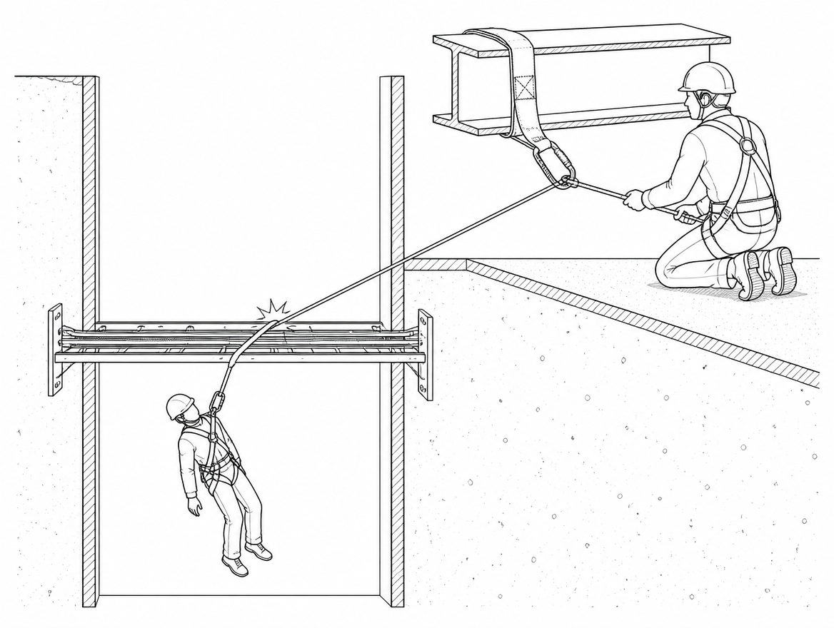
The moment a rescue system needs to change direction is the moment most improvised rigging fails. A casualty being lowered down a shaft snags a cable tray two metres from the floor. A confined-space entrant who walked in on their own feet has to come out vertically. A stretcher on a facade drops onto a ledge that turns out to be the wrong side of a projection. In every one of these cases the crew does not need a new system – it needs the system already under load to reverse, under control, without the load ever being unsupported. A combined lowering raising haul system is rigged from the outset so that reversal is a rehearsed sequence of moves rather than an improvisation over an edge.
This article covers what the configuration is, which components and EN standards apply, the changeover sequence in both directions, the force accounting that decides whether the anchor and the rope are adequate, and the failure modes that recur when a crew converts a one-directional system on the fly.
What “combined” actually means in this context
Two distinct approaches both get called a combined system, and they carry different risks:
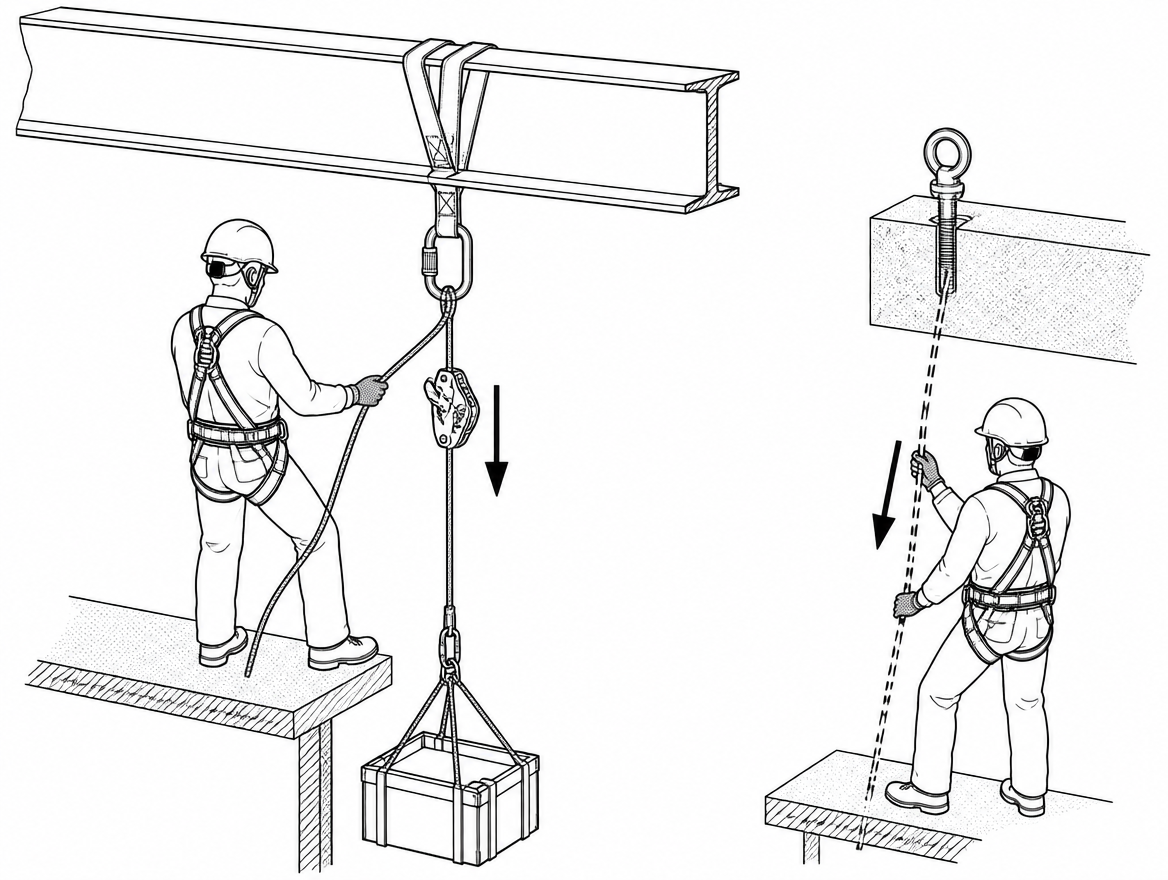
- A convertible single-line system. The load hangs on one working line controlled by a descender at the anchor. To raise, a progress-capture device and a mechanical-advantage set are added to the same line on the load side of the descender. To lower again, the load is returned to the descender. The rope, the anchor and the connection to the load never change – only the direction of travel and the device carrying the load.
- A purpose-built raising and lowering device. Rescue lifting devices are classified under EN 1496, and the distinction matters: Class A devices raise only, Class B devices raise and lower. If a tripod or davit winch on site is a Class A unit, it cannot legally or mechanically be used to pay a casualty back down, and any plan that assumes it can is defective.
Both approaches sit alongside a second, independently anchored line. In rope access work, EN 12841 is built around the principle of a working line and a separate safety line, with a Type A backup device on the safety line, a Type B ascender and a Type C descender. Rescue rigging follows the same logic: whichever way the working line is running, the second line stays under the control of a dedicated operator.
Components and the standards that apply to them
Specify the system by declared rating, not by habit. A crew that plans for a two-person rescue load – typically taken as 200 kg for a casualty plus attendant – cannot build it out of equipment certified for a single 100 kg rope-access user.
- Rope: low-stretch kernmantle to EN 1891. Type A is the usual choice for rescue loads; Type B has lower strength requirements and a narrower field of use. Dynamic mountaineering rope to EN 892 is not a hauling rope – its elongation makes progress capture and edge management unmanageable.
- Descender: a device the manufacturer declares for the intended load. EN 12841 Type C covers descenders for single-person rope access; EN 341 covers descender devices for rescue and is where two-person declarations are normally found. Read the declared maximum rated load and the declared descent parameters rather than assuming.
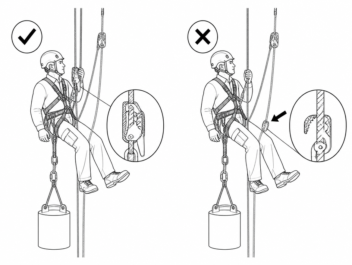
- Progress capture: either a toothed rope clamp (EN 567 for mountaineering rope clamps, or an EN 12841 Type B ascender) or a friction hitch arrangement such as tandem prusiks. Toothed cams are limited by sheath damage well below the rope’s breaking strength, so the manufacturer’s declared maximum load governs. Friction hitches slip before they cut, which is why many rescue teams prefer them at higher loads.
- Pulleys: to EN 12278, sized for the rope diameter in use. Efficiency is not fixed by the standard – manufacturer-declared figures range from roughly 70 per cent for simple bushing sheaves to over 90 per cent for sealed ball-bearing sheaves. Use the declared figure when you calculate haul force.
- Connectors: to EN 362, with the class chosen for the position (basic, multi-use, anchor or termination). Screwgate or self-locking gates only; all strength figures assume the gate is closed and locked and the connector is loaded along its major axis.
- Anchors: EN 795 anchor devices are type-tested for single-person use. Where more than one person is suspended – which is the normal case in a two-person rescue load, and in any system where a haul team’s force adds to the load – CEN/TS 16415 is the reference for anchor devices intended for use by more than one person simultaneously. Structural anchors formed on site should be assessed against the calculated system forces, not against a rule of thumb.
- Load and harness: full body harness to EN 361, rescue harnesses to EN 1497 and rescue loops to EN 1498 where a casualty is being extracted.
EN 365 sets out the general requirements for instructions for use, marking, periodic examination and records for this family of PPE, including periodic examination by a competent person at intervals of no more than 12 months.
Rigging the lowering half
Build the system for the reversal before the load ever leaves the edge.
- Anchor and rigging plate. Bring the working-line descender, the future progress-capture attachment and the change-of-direction pulley onto a single rigging point layout that is already laid out for the haul – not one that has to be dismantled to make room for it.
- Descender in fixed mode. Mount the descender at the anchor with the load-side rope running to the edge and the tail controlled by a dedicated brake operator. The descender stays in the system for the whole operation; it is never removed to make room for the haul.
- Edge management. Fit edge protection – a roller, edge pad or purpose-made edge frame – at the point of rope contact. On a raise, the rope moves in the opposite direction across the same edge, and any sheath damage caused on the way down is dragged straight back over the load-bearing section.
- Second line. Rig the safety line on an independent anchor with its own operator. During the raise it is taken in; during the lower it is paid out. It is never left slack against the assumption that the working line will hold.
- Slack management. Bag or flake the tail so a haul team can move without standing on rope, and so the descender tail is free to run when the direction changes again.
Changing over from lower to raise
The lower-to-raise conversion is the easier of the two directions, because the load is being taken onto the progress capture rather than off it.
- Stop the lower on command and hold the load on the descender.
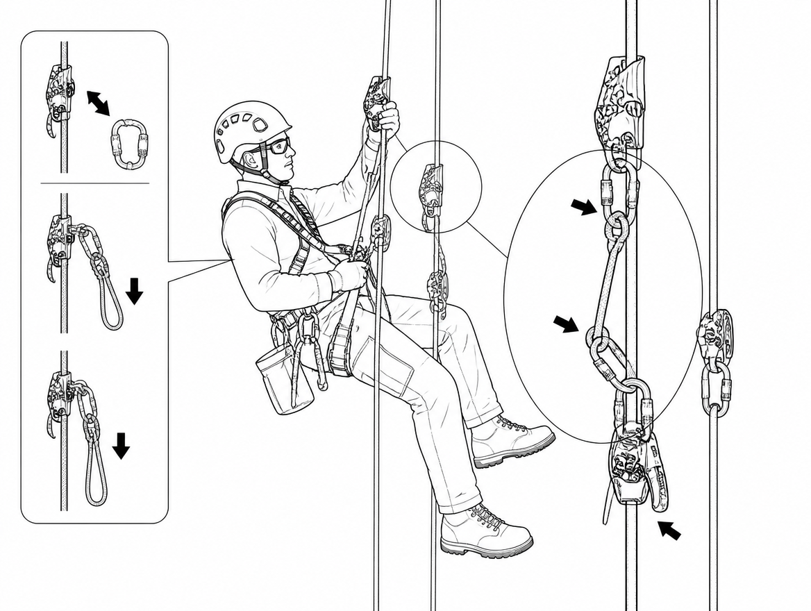
- Attach the progress-capture device to the working line on the load side of the descender, oriented so it grips towards the load and runs free towards the anchor.
- Build the mechanical-advantage set – most commonly a 3:1 Z-rig on the same line, or a separate 4:1 piggyback attached with a rope clamp – and run the haul line through the change-of-direction pulley to the haul team.
- Take up slack until the progress capture is loaded and the descender’s load-side rope is visibly slack.
- Haul on command, in short controlled pulls, with the descender operator keeping the tail managed and ready to take the load back at any moment.
Two points decide whether this stays safe. First, the descender remains rigged and captive on the same line throughout – it is the return path. Second, the progress capture is reset only while the haul is stationary and the edge attendant has confirmed the load is clear of obstructions.
Changing back from raise to lower: the critical transfer
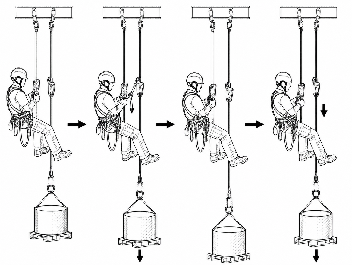
Reversing direction is where systems fail, because the load has to come off a device that grips in only one direction. It cannot simply be released.
Two arrangements solve it:
- Captive descender. The descender stays in line between the anchor and the load for the whole operation. To lower, the haul team takes tension back onto the mechanical-advantage set, the progress capture is unloaded and removed, and the load is fed back onto the descender. This only works if the haul set has enough travel left to lift the load off the capture device – which is why the capture is reset with the load as close to the anchor-side as the geometry allows, rather than at the far end of its stroke.
- Releasable attachment. The progress-capture device is attached to the anchor through a load-releasing hitch or a comparable releasable, controlled-slip arrangement, so tension can be paid off it in a controlled manner until the descender takes the load. The releasable element must be rigged with enough usable travel for the transfer and must be operated by one nominated person on command.
What is not acceptable is a system in which the load sits entirely on a toothed cam or a captured hitch with no controlled means of releasing it – the crew is then choosing between cutting a loaded rope and shock-loading whatever is left.
Force accounting: what the anchor and the rope actually see
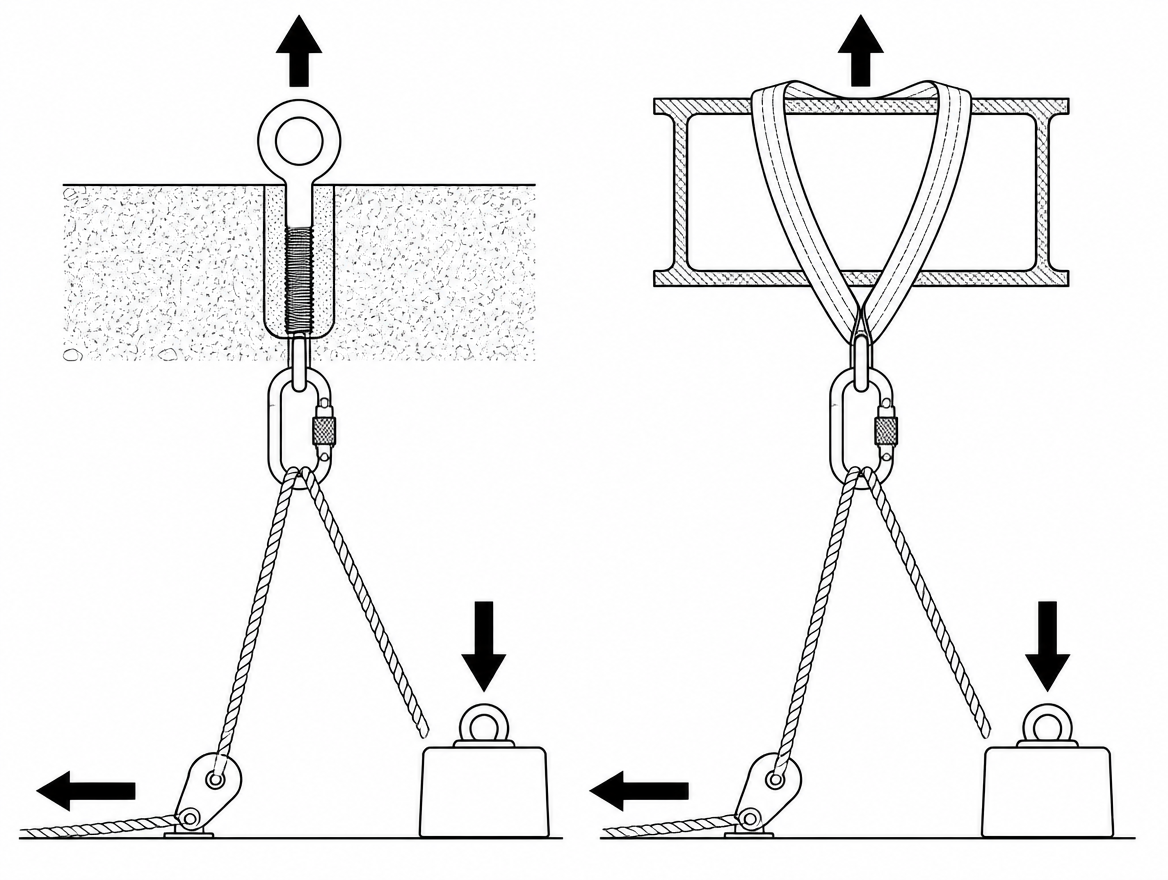
A haul team is a force multiplier that does not know when to stop. Work the numbers before rigging, using a two-person rescue load of 200 kg (approximately 2 kN) as the worked example.
- Theoretical against real advantage. A 3:1 haul needs roughly one third of the load at the haul line in a frictionless system. With declared pulley efficiencies applied and rope bend at the edge included, the real figure is meaningfully worse – which is exactly why a haul team can be pulling far harder than the mechanical advantage suggests without feeling that anything is wrong.
- Anchor load. In a Z-rig where the haul line is redirected at the anchor, the anchor carries the load plus the haul force plus the redirect. For a 2 kN load this approaches twice the load at the anchor, before any dynamic effect is counted.
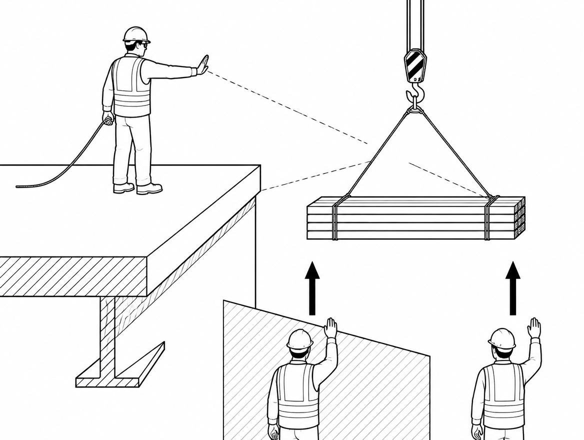
- Jammed loads. If the stretcher fouls, the haul team’s force goes into the obstruction and the rope, not into lifting. Four haulers on a 4:1 can generate forces well above anything the casualty or the rigging is intended to see. The control for this is procedural: the edge attendant calls the stop, and the haul stops on the call, not when the rope feels heavy.
Where a system is used routinely at close to its design load, an inline load cell gives the haul captain a real number instead of an impression.
Roles and commands
A convertible system has more moving parts than a simple lower, and the changeover is the point where two people can both believe they are holding the load. Assign the roles explicitly before rigging:
- Systems or haul captain – owns the direction of travel and the changeover sequence, and is the only voice that starts and stops movement.
- Brake operator – controls the descender, and confirms out loud when the load is on it and when it is off.
- Progress-capture operator – attends and resets the capture device, and confirms out loud when it is loaded and when it is clear.
- Safety-line operator – manages the second line independently in both directions.
- Edge attendant – the only person who can see the load and the edge, and holds an unconditional stop call.
Keep commands short, distinct and confirmed back. “Stop”, “haul”, “lower”, “on the capture”, “on the brake” – and no movement between a command and its confirmation.
Recurring failure modes
- Descender removed to build the haul. The return path disappears, and the crew discovers it when the load has to go back down.
- Progress capture with no releasable path. Covered above; it converts a controllable situation into a cutting problem.
- Capture reset at the end of its travel. Leaves no stroke available to lift the load off the capture for a transfer back to the descender.
- Toothed cam beyond its declared load. The cam damages the sheath long before the rope fails. Any rope that has been arrested or slipped under a toothed device is withdrawn for examination.
- Single-person-rated components in a two-person system. Mixing an EN 12841 single-user device into a 200 kg rescue load is a specification error, not a judgement call.
- Anchor assessed for one person. EN 795 type testing is single-user; multi-user anchor devices are addressed by CEN/TS 16415, and site-formed structural anchors need calculating against the actual system forces.
- Unprotected edge on the return trip. Sheath damage created on the lower is dragged back across the load-bearing section on the raise.
- Haul continuing into a jam. Almost always a communications failure rather than an equipment failure.
Inspection, records and rehearsal
Pre-use checks on every component are carried out by the user: sheath condition along the working length, cam and spring function, sheave rotation, gate and locking function on every connector, and legible markings on the equipment itself. EN 365 requires periodic examination by a competent person at intervals not exceeding 12 months, with records kept for each item, and specifies the information the manufacturer’s instructions must provide – including inspection criteria and withdrawal conditions.
Rigging competence for this configuration is perishable in a way that a simple lower is not. The changeover in both directions is the part that has to be drilled – with a weighted test load, at the actual site geometry, with the roles assigned as they would be on the day. Under ISO 45001:2018, emergency preparedness and response (clause 8.2) requires planned response to identified emergency situations including periodic testing and exercising of the planned response, and the review of that response afterwards. A rescue plan that names a combined system without evidence that the crew has performed the transfer under load is not a tested response.
The takeaway
Build every lower as if it will have to become a raise, and every raise as if it will have to become a lower. Practically, that means three things: the descender stays captive in the working line for the whole operation, the progress capture is attached through something that can be released under control, and the mechanical-advantage set is reset with enough travel to lift the load off the capture. Add the declared load ratings for every component in the chain, the anchor forces the haul team can generate, and a single voice controlling direction – and the system will change direction the same way in a shaft at midnight as it does in the training bay.
Next step: check each device in your rescue kit against its declared maximum rated load and its certification – EN 341, EN 12841, EN 1496 Class A or Class B, EN 567 – and confirm that the set as assembled is rated for the two-person load your rescue plan assumes.
Frequently asked questions
What does a "combined" lowering and raising system actually mean?
Two distinct approaches are both called combined. The first is a convertible single-line system, where the load hangs on one working line controlled by a descender at the anchor, and a progress-capture device plus a mechanical-advantage set are added to the same line on the load side of the descender in order to raise; the rope, anchor and connection to the load never change, only the direction of travel and the device carrying the load. The second is a purpose-built raising and lowering device. Both approaches sit alongside a second, independently anchored line.
Why does the EN 1496 class of a rescue lifting device matter?
Rescue lifting devices are classified under EN 1496, and the distinction is important: Class A devices raise only, while Class B devices raise and lower. If a tripod or davit winch on site is a Class A unit, it cannot legally or mechanically be used to pay a casualty back down, so any plan that assumes it can is defective.
Which rope is appropriate for a hauling system?
Low-stretch kernmantle rope to EN 1891, with Type A the usual choice for rescue loads; Type B has lower strength requirements and a narrower field of use. Dynamic mountaineering rope to EN 892 is not a hauling rope, because its elongation makes progress capture and edge management unmanageable.
What are the options for progress capture, and how do they differ?
Either a toothed rope clamp (EN 567 for mountaineering rope clamps, or an EN 12841 Type B ascender) or a friction hitch arrangement such as tandem prusiks. Toothed cams are limited by sheath damage well below the rope's breaking strength, so the manufacturer's declared maximum load governs. Friction hitches slip before they cut, which is why many rescue teams prefer them at higher loads.
What anchor standard applies when more than one person is suspended?
EN 795 anchor devices are type-tested for single-person use. Where more than one person is suspended – the normal case with a two-person rescue load of around 200 kg, and in any system where a haul team's force adds to the load – CEN/TS 16415 is the reference for anchor devices intended for use by more than one person simultaneously. Structural anchors formed on site should be assessed against the calculated system forces, not against a rule of thumb.
Need this as a document you can issue? The template library gives you the risk assessments, permits and inspection logs in editable form — and employer plans cover a whole team with completion records.