Safety / Tips and Tricks / Rope access and confined space
Activity 01 · Rope access
Function Testing a Rope Grab Every Time It’s Installed
A guided type fall arrester — the rope grab that travels with a worker up a vertical anchor line — is one of the few pieces of fall protection equipment whose correct operation can be confirmed by hand in under a minute, at the point of use, by the person who will be relying on it. A rope grab that is fitted upside down, fitted to the wrong anchor line, or fitted to a rope whose sheath is glazed or iced will still look installed. It will still hold the connector. It will simply not brake when it is asked to. The function test is what separates "the device is on the rope" from "the device works on this rope, today, in this condition."
This article sets out what a rope grab function test covers, the sequence to run it in, what a failure looks like, and where the test’s limits are — because a passed function test says nothing about the clearance below the worker’s feet.
Why the test is repeated at every installation, not just at the annual examination
EN 365 sets the framework for instructions for use, periodic examination and records for personal fall protection equipment, and a periodic examination by a competent person at intervals of no more than 12 months is the baseline expectation for equipment of this kind. That examination is a detailed, documented inspection — but it happens away from the job, on a rope that may not be the rope in use today, in conditions that are not site conditions.
The pre-use check and function test exist because almost everything that defeats a rope grab happens between examinations: the device is transferred to a different anchor line, the rope picks up cement slurry or spray paint, the line freezes overnight, the cam mechanism takes a knock in a tool bag, or the device is simply clipped on the wrong way round in poor light. Guided type fall arresters for flexible anchor lines are covered by EN 353-2, and the instructions supplied under that standard are written on the assumption that the user checks function before each use — not that the annual examination will catch it.
The device and the anchor line are one certified system
This is the single most common installation error and it precedes the function test, because if it is wrong the test result is meaningless.
Under EN 353-2, a guided type fall arrester is type-tested together with its anchor line, its terminations and any integral energy absorber or connecting lanyard. The certification covers that assembly. Fitting a device onto a rope of a different diameter, a different construction, or a different manufacturer takes the assembly outside the tested configuration — even where the rope is a perfectly good EN 1891 Type A low-stretch kernmantle line in its own right. Braking performance in these devices depends on the cam geometry acting against a specific rope diameter and sheath construction. A rope 1 mm thinner than specified can allow the cam to pass without gripping; a rope with a harder or more slippery sheath finish can allow it to slip a long way before it bites.
Before touching the device, confirm three things:
- The anchor line is the one identified in the device’s instructions for use — diameter, construction and manufacturer.
- Any lanyard, energy absorber or connector between the device and the harness is the one supplied or explicitly permitted by the manufacturer. Adding an extension lanyard changes fall distance and, in some designs, prevents the device from locking correctly.
- The device’s markings are legible. Where identification, standard reference and serial number can no longer be read, the equipment cannot be traced to its examination record and should be withdrawn.
Installing the device: orientation and attachment
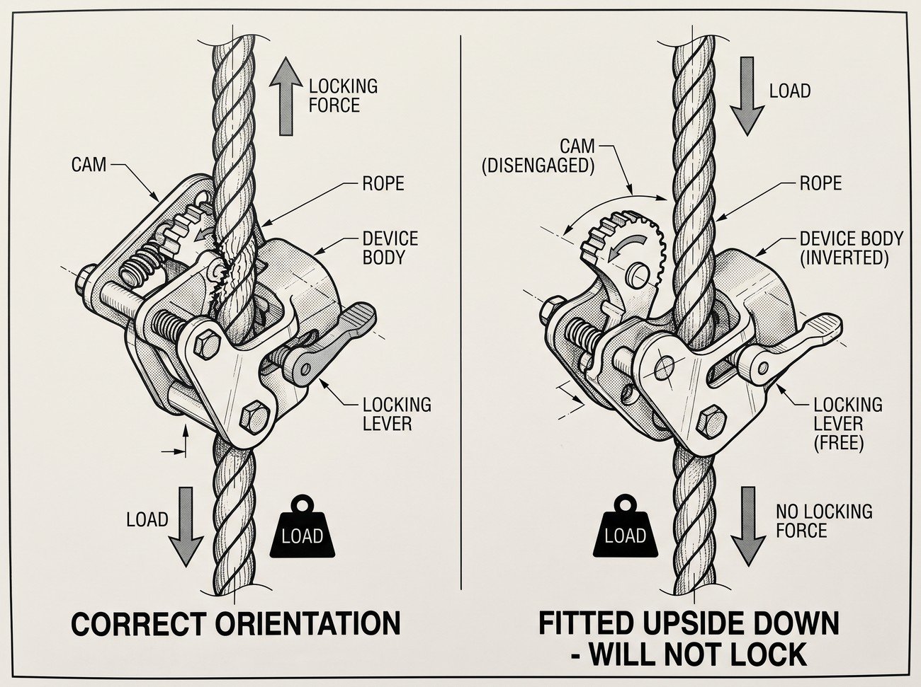
Guided type fall arresters are directional. The body carries a permanent indication of which end must face upward, toward the anchor; installed inverted, most designs will slide freely in both directions and never engage. Orientation is checked visually at installation and confirmed again by the lock-up test described below.
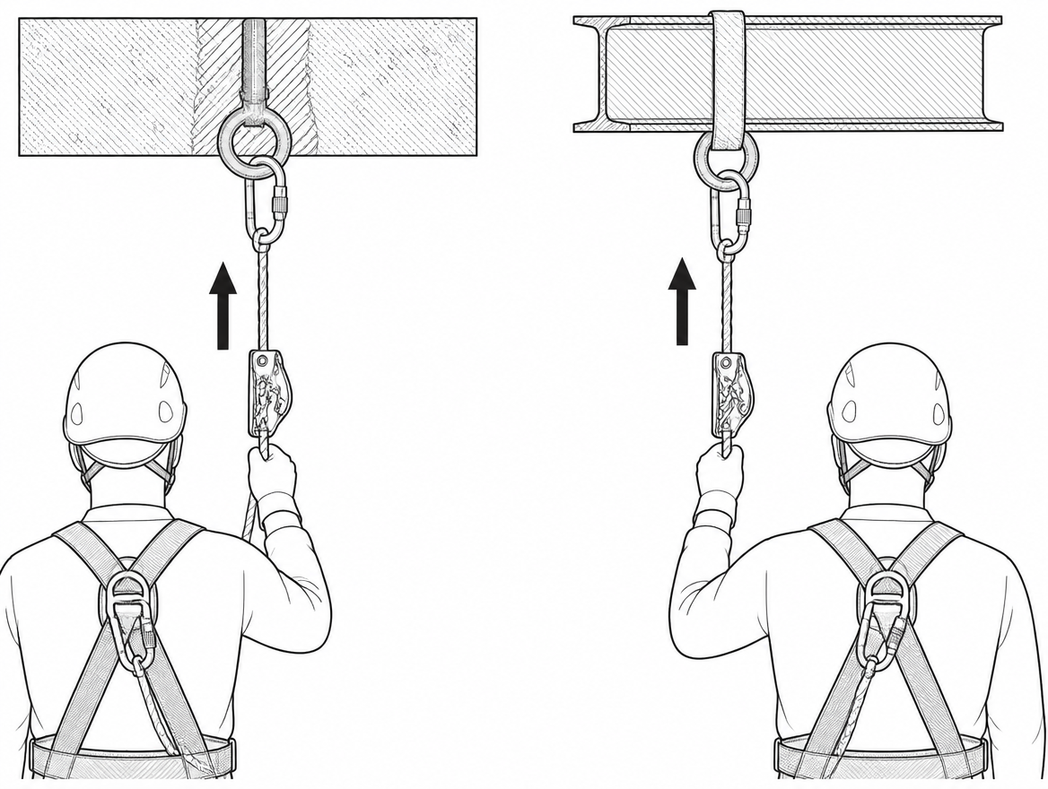
The device connects to the fall arrest attachment point of an EN 361 full body harness — the sternal or dorsal attachment, and nothing else. Waist belt loops, side positioning D-rings and equipment loops are not fall arrest attachments and are not rated for arrest forces. Where the device has an integral lanyard or energy absorber, it is used at the length supplied, without knots, wraps or additional connectors.
Checking the anchor line before the test
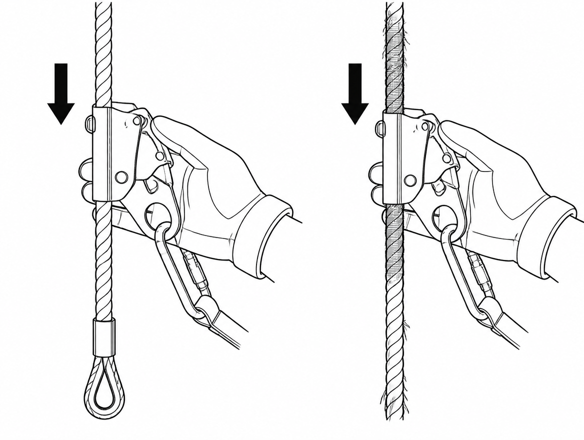
The rope is part of the brake. Run the accessible length of the line through the hands and look for:
- Sheath abrasion, cuts, or fibre loss exposing the core.
- Glazed or fused areas — a hard, shiny, often flattened patch caused by heat, friction or a previous arrest. Glazing reduces the grip the cam can develop.
- Contamination: paint, resin, oil, cement, mud, ice. Any of these can act as a lubricant between cam and sheath.
- Stiff, soft or lumpy sections indicating internal core damage.
- Condition of terminations, and the presence of the lower end stop or termination that prevents the device from running off the end of the line.
- Correct tensioning arrangement where the design calls for a tensioning weight or bottom anchor.
The upper anchor is checked at the same time: a fixed anchor device to EN 795, with the connector correctly seated and no evidence of movement, corrosion or damage to the structure around it.
The function test: free travel, lock-up, release
The test is performed at ground level or from a protected position, before the anchor line is relied upon, with the worker still secured by other means where the installation is at height. It has three parts, run in order.
1. Free travel
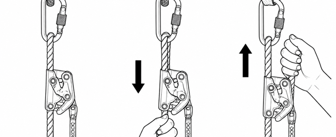
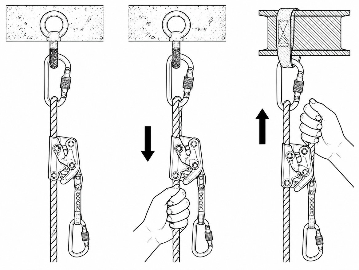
With the device correctly oriented on the line, slide it upward and downward by hand through at least a metre of travel. It should follow smoothly in both directions without needing to be forced, and without the cam snatching intermittently. A device that has to be dragged, or that jams and releases erratically, has a fouled or damaged mechanism.
2. Lock-up
Apply a brisk downward pull on the device — by hand on the attachment eye, or in the manner specified in the instructions for use. The cam must rotate and clamp the rope immediately, with only minimal travel before it holds. This is also the definitive check on orientation: a device fitted the wrong way up will slide instead of locking.
3. Release and re-set
Relieve the load. The cam should release cleanly and the device should slide freely again without needing to be worked loose. A device that stays locked after unloading, or that needs to be levered open, will not follow the worker up the line and invites the worker to hold it or override it — which is how devices end up defeated.
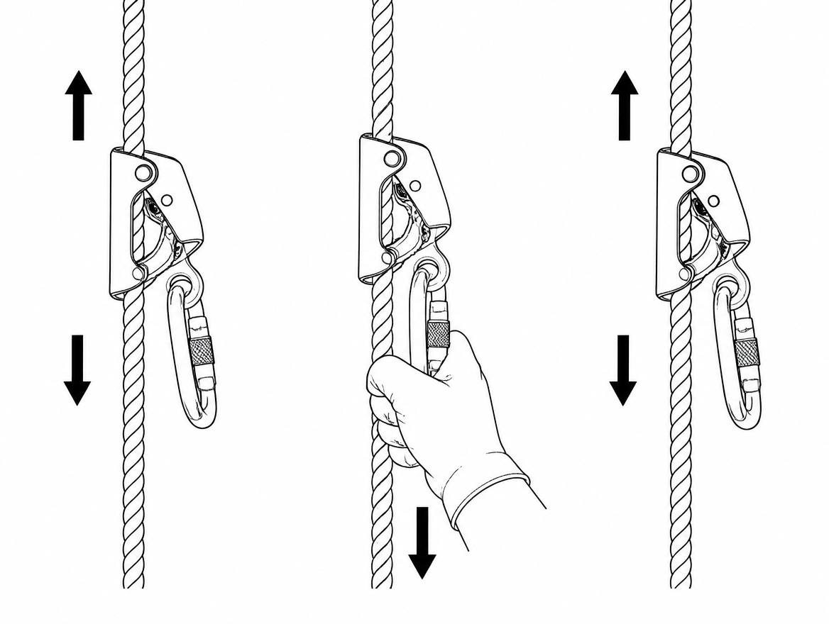
Where the manufacturer’s instructions permit a controlled body-weight check at ground level, that is a useful confirmation. What is never a function test is taking a fall, or shock-loading the device to see whether it holds.
What a failed function test looks like
Any of the following ends the test and takes the assembly out of service:
- The device does not lock, or slips a significant distance before locking.
- The cam is sluggish, sticky, or does not return under its own spring force.
- Cam teeth are worn smooth, chipped, or clogged with paint, ice or hardened material.
- The housing is bent, cracked, or has been forced apart; rivets or pivot pins are loose or corroded.
- The device can be fitted to the line in more than one orientation, or can be removed mid-line where the design does not allow it.
- Any evidence of a previous arrest — deformation, a witness mark on the rope, a deployed energy absorber, a torn tear-stitch cover.
A failed device is tagged, physically segregated from serviceable stock, and referred to a competent person. Equipment left “aside to look at later” in a shared kit store returns to use.
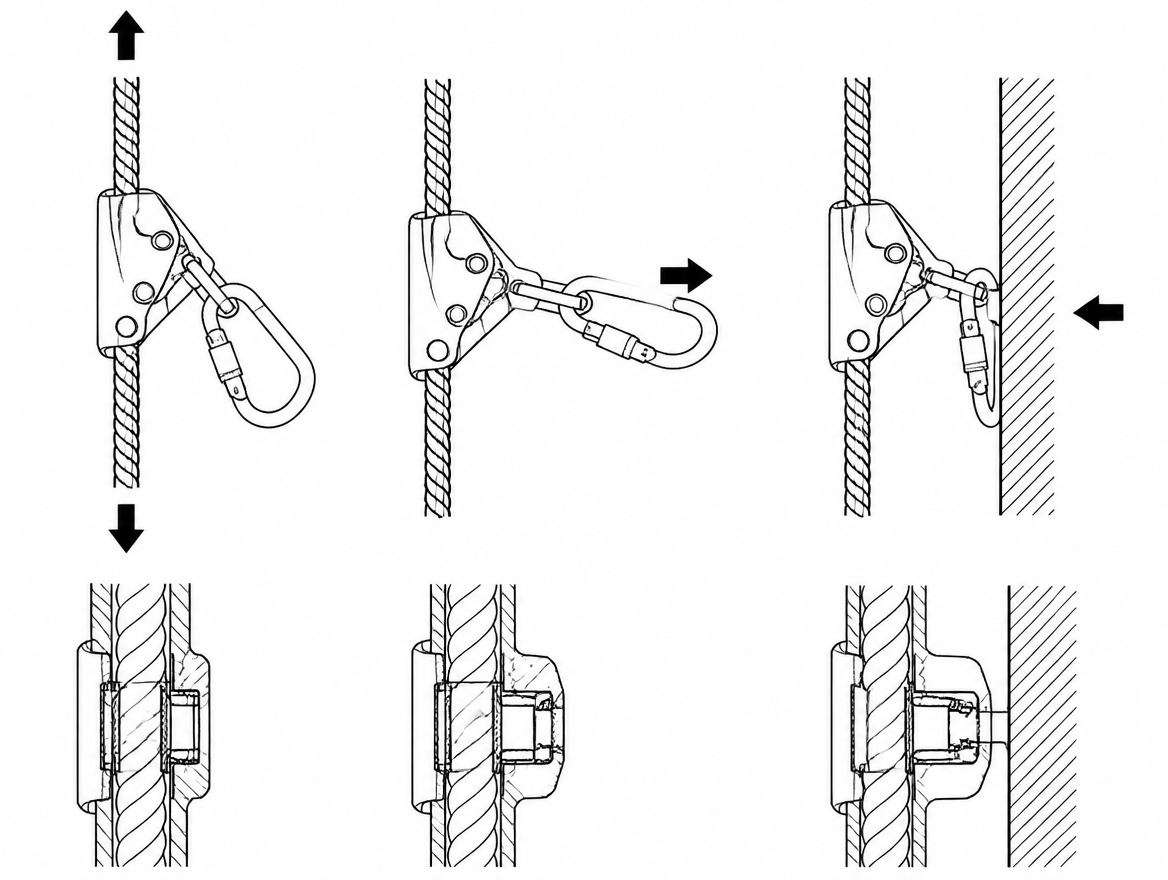
The connector is part of the test
Connectors to EN 362 fail in predictable ways, and the moment after installing a rope grab is the moment to check them. Confirm the gate closes fully under its own action and that a screwgate or twist-lock is actually locked, not just resting closed. Confirm the connector is loaded along its major axis, seated at the base of the basket, with the gate free of contact against the harness attachment, the device eye or the structure. Cross-loading and gate-loading reduce the strength of a connector dramatically compared with its rated major-axis strength.
What the function test does not tell you: clearance
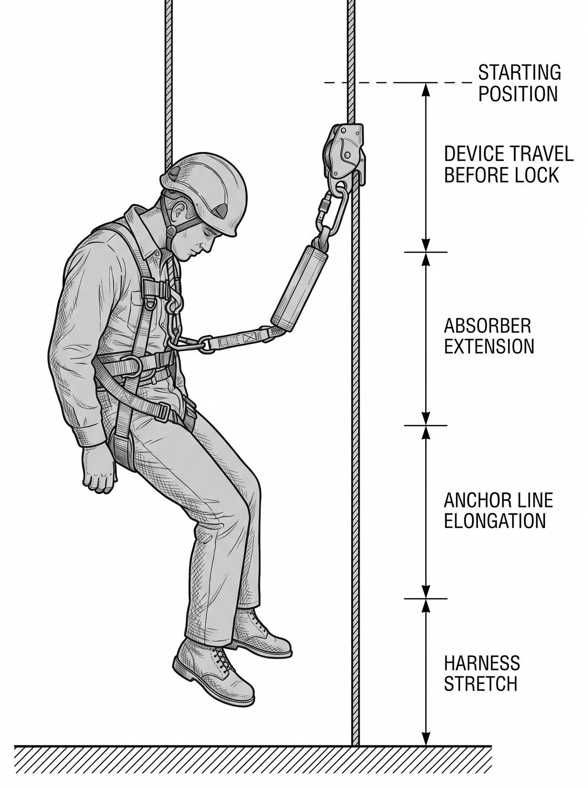
A device that locks perfectly still needs space below the worker to do its job. Required clearance for a guided type fall arrester is stated in the manufacturer’s instructions for use, and it is the sum of several distances, not a single figure to estimate on site:
- The distance the device travels along the line before locking.
- Extension of any integral energy absorber.
- Elongation of the anchor line under load, which depends on the length of line above the device.
- Harness stretch and the displacement of the worker’s body in the harness.
- A safety margin to the ground or the nearest obstruction.
Because line elongation varies with the deployed length above the device, clearance is worst near the bottom of a long line — precisely where workers assume they are safest. Take the figure and the method from the instructions supplied with the specific device and line, and check it against the actual obstruction below: scaffold platforms, pipework, plant, vehicles and stacked material all count.
Recording the check
The function test is a user check, not a formal examination, and it does not replace the periodic examination by a competent person under EN 365. It does, however, produce information worth keeping. Organisations operating a management system to ISO 45001 are expected to retain documented information proportionate to the risk, and vertical fall arrest sits at the top of that scale. A workable arrangement is a short pre-use entry against the device’s serial number — date, user, line identity, pass or fail — with any failure triggering a defect report rather than an entry in a log nobody reads.
The one-minute sequence, in order
- Confirm the anchor line matches the device’s instructions for use, and the anchor is a serviceable EN 795 device.
- Check device markings are legible and traceable; check housing, cam and rivets for damage.
- Inspect the line for abrasion, glazing, contamination, ice, and the lower end stop.
- Fit the device the correct way up, with only the supplied lanyard or energy absorber.
- Connect to the sternal or dorsal fall arrest attachment of an EN 361 harness; lock the EN 362 connector and check its loading axis.
- Slide up and down — free travel. Pull sharply down — immediate lock. Unload — clean release.
- Confirm the clearance below meets the figure in the instructions for use for the deployed line length.
If any step fails, the assembly comes out of service and goes to a competent person. Next step worth reading alongside this: the pre-use inspection criteria for anchor lines and EN 795 anchor devices, and the periodic examination record requirements set out in EN 365 for the equipment already in your kit store.
Frequently asked questions
Why run a function test at every installation if the device already has an annual examination?
The periodic examination by a competent person, at intervals of no more than 12 months under the EN 365 framework, is detailed and documented but happens away from the job, often on a rope that is not the rope in use today and in conditions that are not site conditions. Almost everything that defeats a rope grab happens between examinations: the device is transferred to a different anchor line, the rope picks up cement slurry or spray paint, the line freezes overnight, the cam mechanism takes a knock in a tool bag, or the device is clipped on the wrong way round in poor light.
Can a rope grab be used on any good-quality low-stretch rope?
No. Under EN 353-2 a guided type fall arrester is type-tested together with its anchor line, its terminations and any integral energy absorber or connecting lanyard, and the certification covers that assembly. Fitting the device to a rope of a different diameter, construction or manufacturer takes the assembly outside the tested configuration, even where that rope is a perfectly good EN 1891 Type A low-stretch kernmantle line in its own right. A rope 1 mm thinner than specified can allow the cam to pass without gripping, and a harder or more slippery sheath finish can allow it to slip a long way before it bites.
What should be confirmed before the device is even touched?
Three things: that the anchor line is the one identified in the device's instructions for use by diameter, construction and manufacturer; that any lanyard, energy absorber or connector between the device and the harness is the one supplied or explicitly permitted by the manufacturer; and that the device's markings are legible. Adding an extension lanyard changes fall distance and, in some designs, prevents the device from locking correctly. Where identification, standard reference and serial number can no longer be read, the equipment cannot be traced to its examination record and should be withdrawn.
Why does orientation matter, and where should the device be connected on the harness?
Guided type fall arresters are directional. The body carries a permanent indication of which end must face upward, toward the anchor; installed inverted, most designs will slide freely in both directions and never engage. Orientation is checked visually at installation and confirmed again by the lock-up test. The device connects only to the fall arrest attachment point of an EN 361 full body harness — the sternal or dorsal attachment. Waist belt loops, side positioning D-rings and equipment loops are not fall arrest attachments and are not rated for arrest forces. Where the device has an integral lanyard or energy absorber, it is used at the length supplied, without knots, wraps or additional connectors.
What is looked for on the anchor line before the test?
The rope is part of the brake, so the accessible length is run through the hands looking for sheath abrasion, cuts or fibre loss exposing the core; glazed or fused areas — hard, shiny, often flattened patches caused by heat, friction or a previous arrest, which reduce the grip the cam can develop; contamination such as paint, resin, oil, cement, mud or ice, any of which can act as a lubricant between cam and sheath; stiff, soft or lumpy sections indicating internal core damage; the condition of terminations and the presence of the lower end stop that prevents the device running off the end of the line; and the correct tensioning arrangement where the design calls for a tensioning weight or bottom anchor. The upper anchor is checked at the same time.
Need this as a document you can issue? The template library gives you the risk assessments, permits and inspection logs in editable form — and employer plans cover a whole team with completion records.