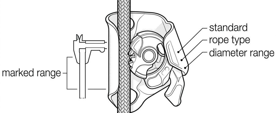
Safety / Tips and Tricks / Rope access and confined space
Activity 01 · Rope access
Rope Grab Specifications and Rope Compatibility: Matching the Device to the Line
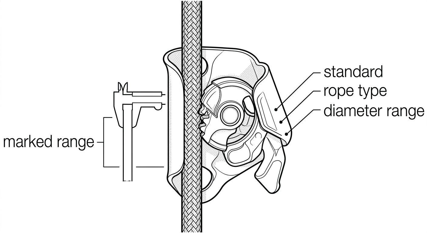
A rope grab is only as good as the rope it is sitting on. The device does not arrest a fall on its own – it does so by clamping a specific type of rope, of a specific diameter, in a specific condition. Put the same device on a line that is a millimetre too thin, too soft, too stiff, iced up or of the wrong construction, and the clamping behaviour that was verified in testing is no longer the behaviour you get on site. This note covers what the specifications on a rope grab actually mean, and how to check that the rope in front of you is inside them.
Two different device families, two different rulebooks
“Rope grab” is used loosely on site for at least two families of device, and their compatibility rules are not identical.
- Guided type fall arresters on a flexible anchor line (EN 353-2). These are the devices you clip to a vertical or inclined lifeline for climbing, ladder access or work on a fixed lifeline. They are certified together with the anchor line, as a single assembly.
- Rope adjustment devices, Type A under EN 12841 (rope access adjustment devices). These are the backup devices used on the safety line of a two-rope rope-access system, alongside a descender or ascender on the working line. They are certified for a stated rope type and diameter range.
Both are marked with the rope they are approved for. The difference is how tightly that approval is bound to one product: with a guided type fall arrester the pairing is usually specific down to the rope model, while a Type A backup is more often approved across a stated diameter range of low-stretch kernmantle rope. Read the device’s own instructions before assuming which case you are in.
The system is certified, not the device on its own
This is the single most misunderstood point about rope grabs. Certification of a guided type fall arrester applies to the device, the anchor line, the terminations, the connector and any integral energy absorber as one tested combination. Swapping the supplied lifeline for a superficially similar rope of the same nominal diameter – a different sheath construction, a different manufacturer, a spare drum from the store – means the assembly you are using is no longer the assembly that was tested.
The practical rule is simple: use the rope named in the device’s instructions, from the same manufacturer, with the terminations the manufacturer supplies or specifies. If the paperwork cannot tell you which rope the device was certified with, the device should not go into service until it can.
Reading the markings on the device
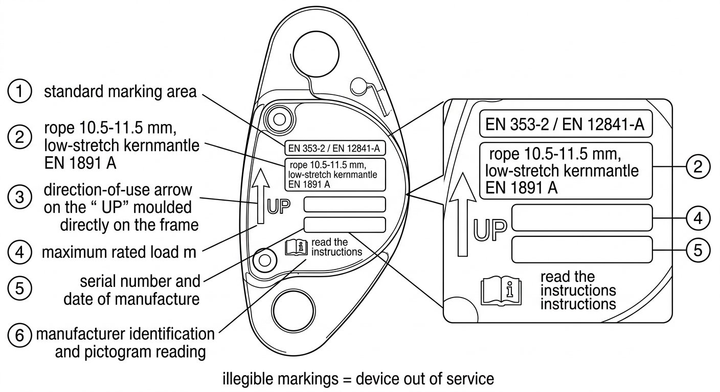
The information you need is nearly always on the side plate or body of the grab. Expect to find:
- The standard(s) the device conforms to – for example EN 353-2, EN 12841 Type A, or both, sometimes alongside non-European marks.
- The rope diameter range, usually as a span in millimetres, and often with the rope type qualified (for example, low-stretch kernmantle rope to EN 1891 Type A).
- A direction-of-use indication – an arrow, the word “UP”, or a moulded figure showing the device orientation relative to the anchor point.
- Maximum rated load or maximum user mass including equipment, where the manufacturer states one.
- Serial or batch number and date of manufacture, needed for the inspection record.
If any of these are worn illegible, the device has lost the information that makes it inspectable. That is a retirement trigger, not a cosmetic problem.
What the diameter range is actually controlling
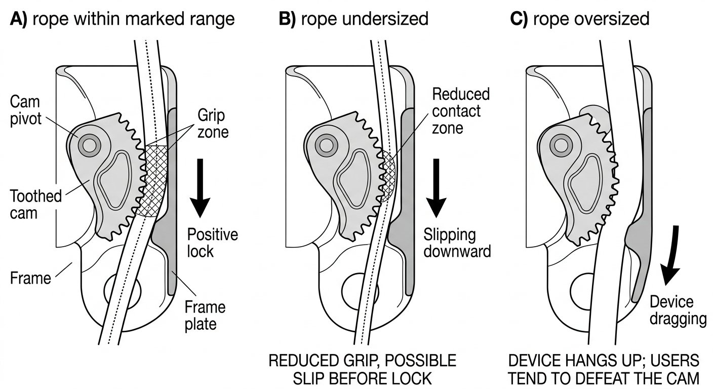
A rope grab works by pinching the rope between a cam (usually toothed or grooved) and a fixed frame or opposing plate. The geometry of that pinch is designed around a narrow band of rope diameters. Outside it, two distinct failure modes appear.
Rope too thin for the device. The cam rotates further before it makes contact, contact area is reduced, and the device may slip along the rope under load before it bites – or fail to lock at all. On some designs an undersized rope also lets the cam over-rotate into a position where teeth can shear the sheath rather than grip it.
Rope too thick for the device. The cam cannot open far enough to let the rope run freely, so the grab drags, hangs up or has to be muscled along. Users then start holding the device open by hand or defeating the cam to make it travel – which removes the arrest function entirely at exactly the wrong moment.
Note that nominal diameter is a label, not a measurement. Ropes are produced to a tolerance, and the same “11 mm” rope from two manufacturers can measure differently, and will measure differently again under tension than slack. When the marked range on a device is narrow, choose a rope comfortably inside it rather than at the extreme edge. The same logic applies across the whole system – see the note on choosing a low-stretch rope diameter to match devices, loads and wear, and on why the marked diameter range on descenders matters, since a single rope usually has to satisfy every device on the job.
Construction, not just diameter
Two ropes of identical diameter can behave completely differently in the same grab. The variables that matter:
- Low-stretch versus dynamic. Rope grabs used in work-at-height systems are designed around low-stretch kernmantle rope (EN 1891, typically Type A for general access and rescue work). Dynamic climbing rope elongates far more under load; a grab specified for low-stretch rope may slip further, generate different arrest forces, or grip erratically on it. Unless the manufacturer explicitly approves dynamic rope, do not use it.
- Sheath hardness and weave. A hard, tightly woven sheath resists tooth penetration and can increase slip. A soft, loosely woven sheath grips more readily but abrades faster under repeated cam engagement.
- Sheath-to-core proportion and slippage. If the sheath can migrate relative to the core, a cam that grips the sheath may bunch it along the rope rather than arrest cleanly. This is one reason approved ropes are specified by model.
- Stiffness and handling. Very stiff rope resists feeding through the grab and can hold a set curve that lifts the device off the line; very limp rope tangles and can fail to hang straight below the user, which some devices need in order to travel.
- Treatments and coatings. Dry-treated, waterproofed or dirt-resistant finishes change surface friction. A device approved for a specific rope was tested on that rope as supplied.
Rope condition changes compatibility over time
Compatibility is not a one-time check at purchase. A rope in service moves within – and eventually outside – the window the grab was designed for.
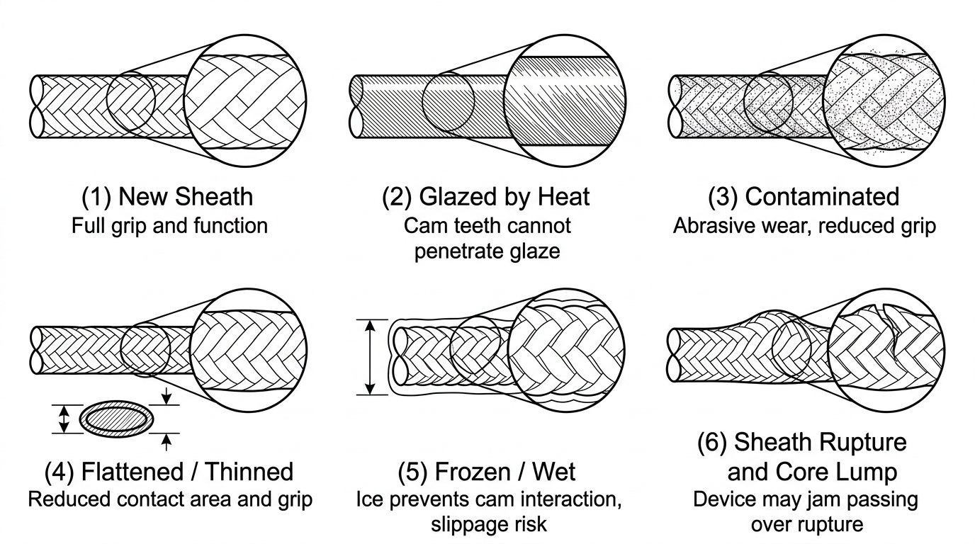
- Diameter drifts. Ropes generally shrink slightly in length and can tighten in diameter after first washing and early loading cycles; later, sustained loading and abrasion can flatten or thin sections. Measured diameter on a used rope is rarely the catalogue figure. The note on performance of new versus used ropes covers how slip, stretch and friction all shift with age.
- Glazing and contamination. A sheath that has been glazed by heat, or loaded with fine dust, cement, drilling mud or oil, becomes slippery and resists cam bite.
- Water and ice. A wet rope is a different rope in a grab; a frozen rope is more so – stiff, enlarged with ice, and with a hard surface the cam teeth cannot penetrate. Cold, wet work needs the manufacturer’s guidance specifically, not an assumption.
- Local damage. Flat spots, sheath ruptures, core lumps and hard-set kinks all interrupt the cam-to-rope contact and can jam or release the device as it passes over them.
Also check the device side of the pair. Cam teeth blunt, fill with grit, or become polished; springs weaken; pivots stiffen. A grab whose teeth have rounded off will slip on rope that is otherwise perfectly serviceable.
Connecting the grab to the harness
Compatibility does not stop at the rope. The link between grab and harness is part of the certified assembly and is frequently the point where field improvisation creeps in.
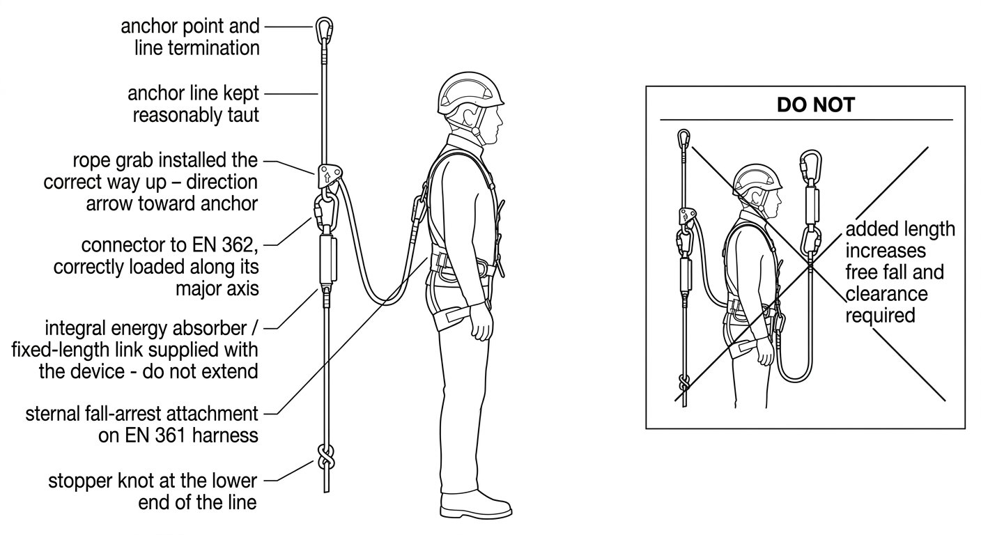
- Use only the connector and lanyard specified. If the device is supplied with an integral energy absorber or a fixed-length link, that element is part of the tested system. Adding a second connector, a longer lanyard or a swivel to make the device sit more comfortably increases free fall and changes the arrest behaviour.
- Attach to a fall-arrest point. That means a sternal or dorsal attachment on a harness conforming to EN 361 (full body harnesses) – never a positioning belt D-ring, gear loop or ventral bridge unless the device instructions explicitly allow it. The distinction, and the consequences of getting it wrong, are set out in the note on harness attachment points for a rope grab.
- Check the connector interface. The connector must fit the grab’s attachment hole without cross-loading or levering over the frame, and must be a locking type to EN 362.
Orientation, travel and rope ends
A correctly matched grab still needs the line set up so it can work.
- Install the device the right way up. Every guided type fall arrester has a defined orientation. Inverted, it may travel freely in the direction of a fall.
- Keep the anchor line reasonably taut and unobstructed. Slack in the line adds to fall distance. Knots, splices, tape wraps and hardware in the path of travel will stop the device or force the user to unclip.
- Terminate the bottom of the line. A stopper knot or manufacturer-specified end termination prevents the grab running off the end of the rope. On installed lifelines, a tensioning weight or bottom anchor may perform this function – check which arrangement the system was certified with.
- Verify clearance below. The device’s arrest distance, the absorber’s deployment and the rope’s own elongation all add up. On short lines and low headroom this is often the governing constraint.
A pre-use compatibility check that takes a minute
- Read the device markings: standard, rope type, diameter range, direction arrow.
- Read the rope markings or its logbook: type, standard, nominal diameter, manufacturer.
- Confirm they match – and for a guided type fall arrester, confirm the rope is the specific line the device is certified with.
- Inspect a length of the rope by hand for flat spots, glazing, stiffness, contamination and sheath damage.
- Inspect the cam, teeth, springs, pivots, frame and gate for wear, grit and deformation, and confirm the markings are still legible.
- Fit the device to the rope and function-test it: it should travel by hand in the intended direction and lock positively when pulled sharply downward, with the rope hanging as it will in use.
- Check the connector and any integral lanyard or absorber for damage, correct locking and correct orientation.
If any step gives an ambiguous answer – the diameter is at the edge of the marked range, the rope’s identity is unknown, the function test feels vague – treat that as a stop, not a judgement call to be made at height.
Takeaway
The specification on a rope grab is a description of a pairing, not of a device. Match the standard, the rope type, the diameter range and the specified connector, verify the rope’s real present condition rather than its catalogue description, and function-test the combination on the ground before it carries anyone. Further technique notes covering rope selection, device compatibility and confined-space procedure are collected on the rope access and confined space hub.
Frequently asked questions
Can I use any rope of the right diameter with my rope grab?
No. Diameter is only one of several variables; sheath construction, stiffness, surface treatment and low-stretch versus dynamic behaviour all change how the cam grips. Guided type fall arresters to EN 353-2 are certified together with a specific anchor line and must be used with that line. Devices approved across a diameter range still specify the rope type, typically low-stretch kernmantle rope.
What is the difference between an EN 353-2 guided type fall arrester and an EN 12841 Type A device?
EN 353-2 covers guided type fall arresters used on a flexible anchor line, certified as a complete assembly with that line and its terminations. EN 12841 Type A covers rope adjustment devices used as a backup on the safety line of a two-rope rope-access system. Some devices are certified to both, but the compatibility rules are stated separately in the instructions and you should read the one that applies to your use.
Why does my rope grab slip on an older rope that used to work fine?
Ropes change in service: sheaths glaze under heat, load up with fine dust or oil, flatten locally, and can thin or tighten with use. Any of these reduces the cam teeth's ability to penetrate and grip. Blunted or grit-packed cam teeth on the device itself produce the same symptom, so inspect both sides of the pairing.
Can I add a longer lanyard between the rope grab and my harness?
Not unless the manufacturer specifies it. Any integral connector, link or energy absorber supplied with the device is part of the certified assembly. Adding length increases the potential free fall, changes the arrest forces and increases the clearance required below the user.
Which harness attachment point should a rope grab be connected to?
A fall-arrest attachment point on a full body harness conforming to EN 361 – normally the sternal point for a guided type fall arrester on a vertical line, or the dorsal point where the device instructions allow. Positioning belt D-rings, gear loops and equipment attachment points are not fall-arrest points and must not be used.
Are rope grabs safe to use on a wet or frozen rope?
Only where the manufacturer addresses it. Water changes the rope's surface friction and stiffness, and ice both enlarges the effective diameter and creates a hard surface the cam teeth cannot penetrate. If the instructions do not cover freezing conditions, treat wet-cold work as outside the tested envelope and seek manufacturer guidance.
Need this as a document you can issue? The template library gives you the risk assessments, permits and inspection logs in editable form — and employer plans cover a whole team with completion records.