Safety / Tips and Tricks / Rope access and confined space
Activity 01 · Rope access
Approaching an Obstacle with a Rope Grab: How to Pass Without Breaking Attachment
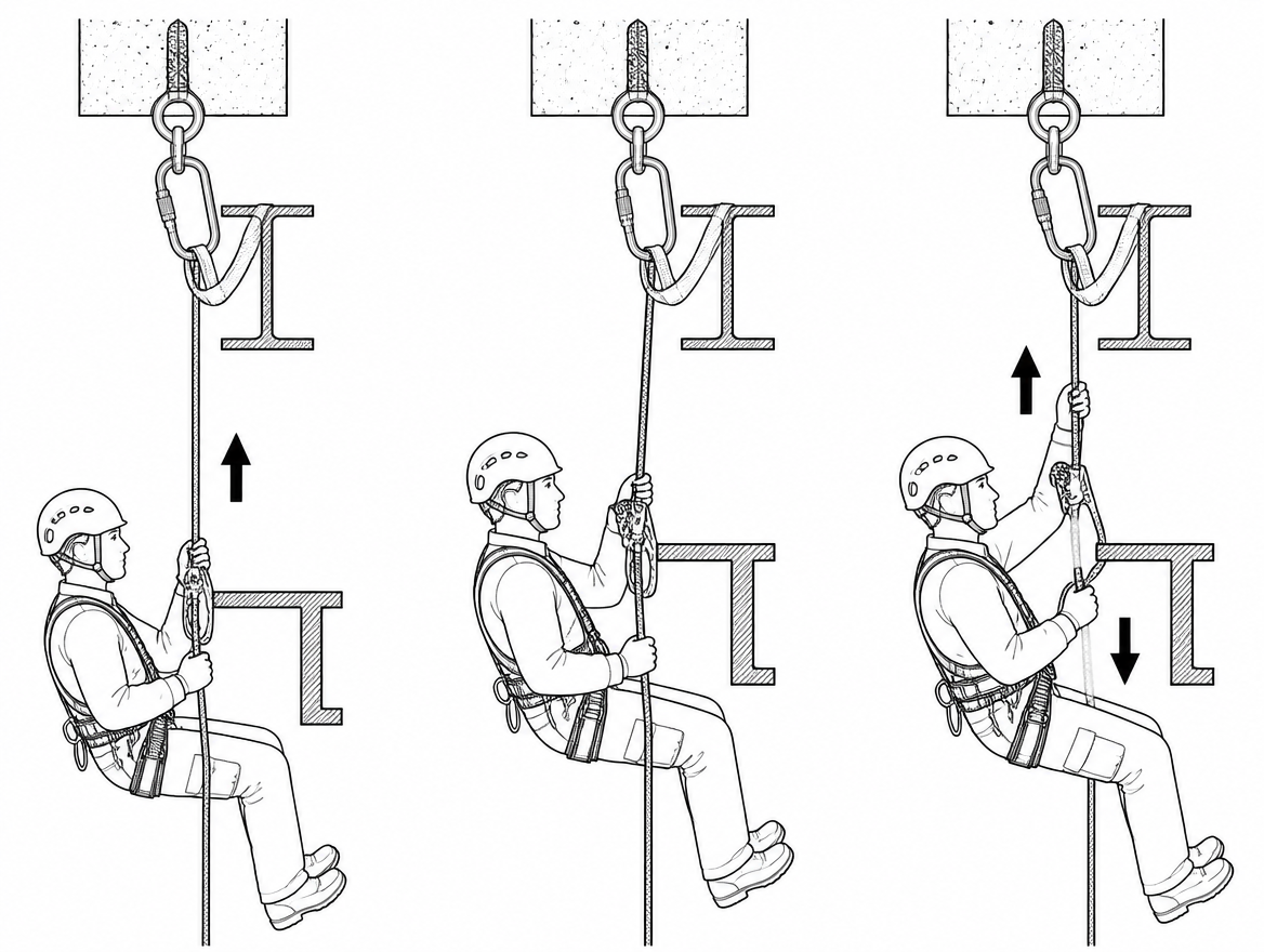
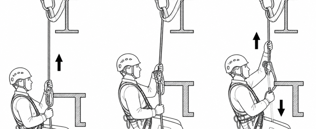
The most dangerous moment in vertical work with a rope grab is rarely the climb itself. It is the second or two when a worker meets an intermediate bracket, a deviation, a pipe run or a knot, cannot get the device past it, and solves the problem the fastest way available: by opening the device and lifting it over. In that instant the fall arrest system does not exist. Rope grab obstacle passing is therefore a procedure that has to be planned before anyone leaves the ground, because the correct answer is decided by the equipment on the line — not by improvisation at height.
This article sets out what counts as an obstacle, what each type of system physically allows, and the sequence for passing an obstacle while attachment to the fall arrest system remains unbroken at all times.
What counts as an obstacle on a vertical line
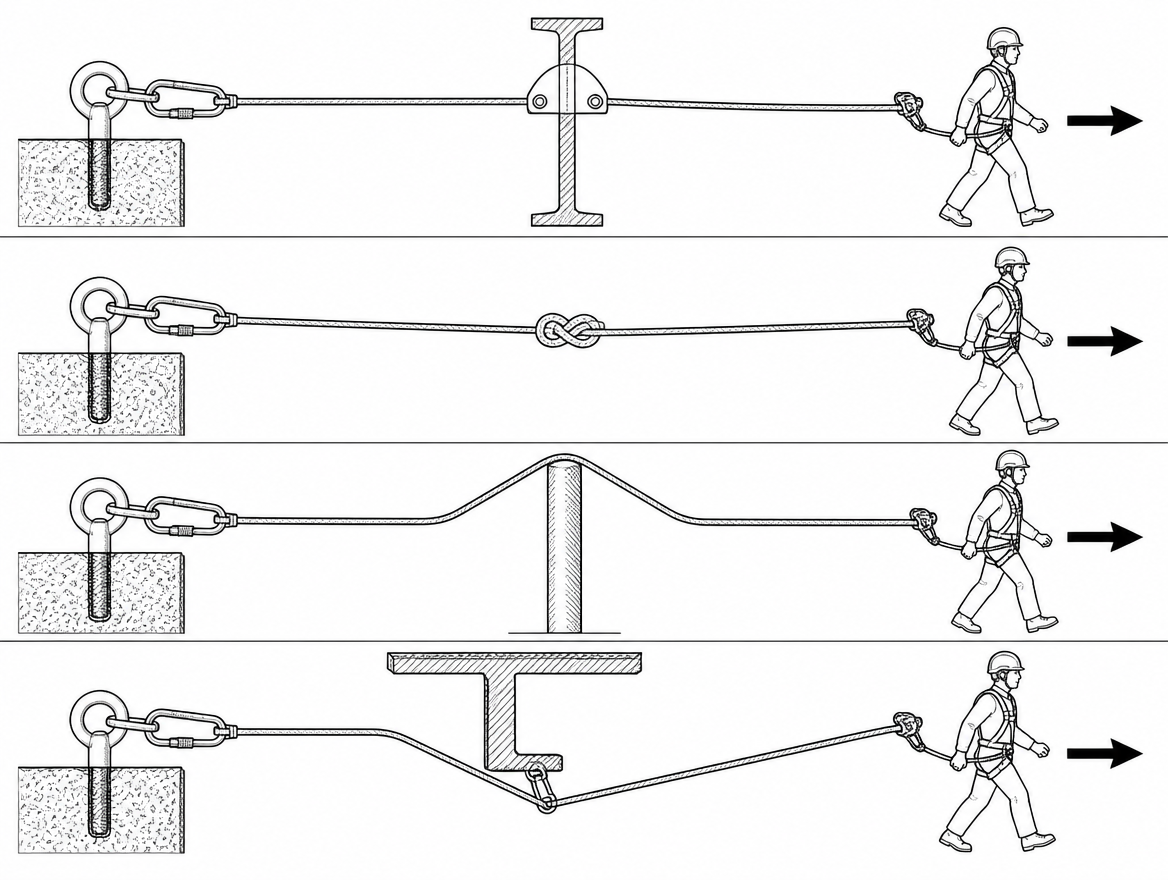
An obstacle is anything on or beside the anchor line that stops a guided type fall arrester from travelling freely. In practice this means:
- Intermediate anchor brackets on a rigid anchor line (rail or cable) fixed to a ladder, mast, chimney or silo.
- Re-belays and intermediate anchors on a rope, where the working and safety lines are re-anchored partway down a drop.
- Deviations that pull the rope sideways away from an edge, a hot surface or a hazard.
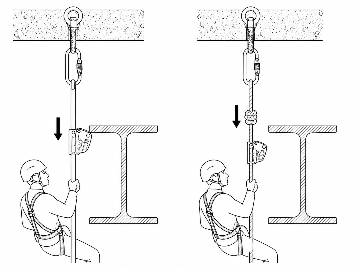
- Knots — mid-line knots, joining knots between rope lengths, or a knot tied deliberately to isolate a damaged section.
- Structural interference: cable trays, brackets, tie-backs, guardrail returns, platform cut-outs and pipework the device must be steered around.
- Edges and transitions where the line changes direction, for example from vertical to a sloped roof plane.
Each of these has a different solution. Treating them as one generic “obstacle” is where planning usually fails.
The rule that governs every obstacle pass: continuity of attachment
A personal fall protection system under EN 363 only protects the user while it is connected. The controlling principle for any obstacle is therefore simple to state and non-negotiable in application: the second attachment is made before the first is released.
There are only three legitimate ways to satisfy that principle when a rope grab meets an obstacle:
- The device is designed to pass the obstacle — typically a guided type fall arrester on a rigid anchor line to EN 353-1, where the intermediate brackets are shaped so the travelling device passes through them without being opened.
- A second, independent attachment carries the user during the transfer — two fall arresters on two lines, or a fall arrester plus a separate connecting device attached to a suitable anchor to EN 795.
- The obstacle is removed from the system before the user goes on the line — the rope is re-rigged, the deviation is repositioned, or the line is replaced with one that has no mid-line knot.
Option three is the one most often overlooked and most often the cheapest. If a knot exists only because two short ropes were joined to make a long one, the correct fix is a single rope of the right length, not a mid-air transfer procedure.
Know which system you are on before you plan the pass
Rigid anchor line systems (EN 353-1)
These are the ladder and mast systems with a fixed rail or a tensioned cable and intermediate guides. The fall arrester, the anchor line and the brackets are certified together as a system. Where the manufacturer states that the device passes the intermediate brackets, the pass requires nothing more than a steady climbing rhythm — the device is never opened, and continuity of attachment is inherent to the design.
Two conditions apply. First, only the device supplied or specified for that anchor line may be used on it; a rope grab from another system is not an interchangeable part. Second, the brackets must be undamaged and correctly aligned, because a bent or mis-set bracket is exactly what causes a device to jam and tempts a user to unclip.
Flexible anchor line systems (EN 353-2)
A guided type fall arrester on a flexible anchor line to EN 353-2 is also certified as a complete system: the device may only be used with the anchor line type, construction and diameter specified by the manufacturer, and usually with the manufacturer’s own terminations. Most of these systems have no provision for passing an intermediate anchor or a knot. If the drop cannot be rigged as a single clean line from top anchor to termination, an EN 353-2 system is the wrong choice for that job.
Rope access systems (EN 12841 and ISO 22846)
Rope access is the one context in which obstacle passing is a routine, taught manoeuvre — because the method rests on two independently anchored ropes. Under EN 12841, rope adjustment devices are classified as Type A (back-up device on the safety line), Type B (ascender on the working line) and Type C (descender on the working line). ISO 22846-1 and ISO 22846-2 set out the fundamental principles and code of practice for working on those systems, including the two-rope approach that makes a re-belay or deviation pass possible without ever leaving the user on a single point.
EN 12841 devices are certified for a stated rope diameter range and are normally used with low-stretch kernmantle rope to EN 1891, which distinguishes Type A rope for general rope access use from the lighter Type B. The permitted diameter range is on the device and in its instructions for use — read it rather than assuming a device will hold on whatever rope is on site.
Passing an intermediate bracket on a rigid anchor line
This is the simplest case and should be treated as a normal part of the climb, not an event.
- Maintain three points of contact on the ladder or structure and keep climbing at a steady pace; do not accelerate into the bracket.
- Keep the device at or above the level of the sternal attachment point of the harness (EN 361), so the connecting element stays short and slack stays out of the system.
- Let the device travel through the guide under its own alignment. Do not grip the device body, and do not push it through by hand — hand pressure on some devices can hold the locking element open.
- If the device stops, stop climbing, take your weight on the structure, and look at why. A deformed bracket, an iced or heavily corroded rail, or a device fitted upside down are the usual causes.
- If the device will not pass and cannot be freed without opening it, the climb ends there. Descend by the way you came up and report the defect for the anchor line to be examined.
A device that jams at a bracket is a defect report, not a puzzle to be solved at height.
Passing an obstacle with two independent devices
Where the system is designed for it and the manufacturer’s instructions permit it, an obstacle is passed by leapfrogging two devices so that at least one is always loaded-capable. The sequence is deliberate and slow.
- Establish a stable stance first. Get your weight onto a rung, step, platform or a work positioning system to EN 358 so that neither transfer device is carrying you during the changeover.
- Attach the second device above the obstacle on the second line, or on the same line above the obstruction where the system allows it. Check the direction of travel, then check that the connector to EN 362 is closed and locked, and that it is on the correct harness attachment point.
- Load-check the new attachment by taking your weight onto it gently and confirming it holds and is correctly oriented, before anything is removed.
- Only now remove the first device from below the obstacle, and reattach it above.
- Restore the normal configuration: device high, slack minimised, connectors closed, no twist in the lanyard, nothing wrapped around a limb, and continue.
The order matters more than the speed. Every incident of this type follows the same pattern in reverse — the old attachment came off first “just for a second”.
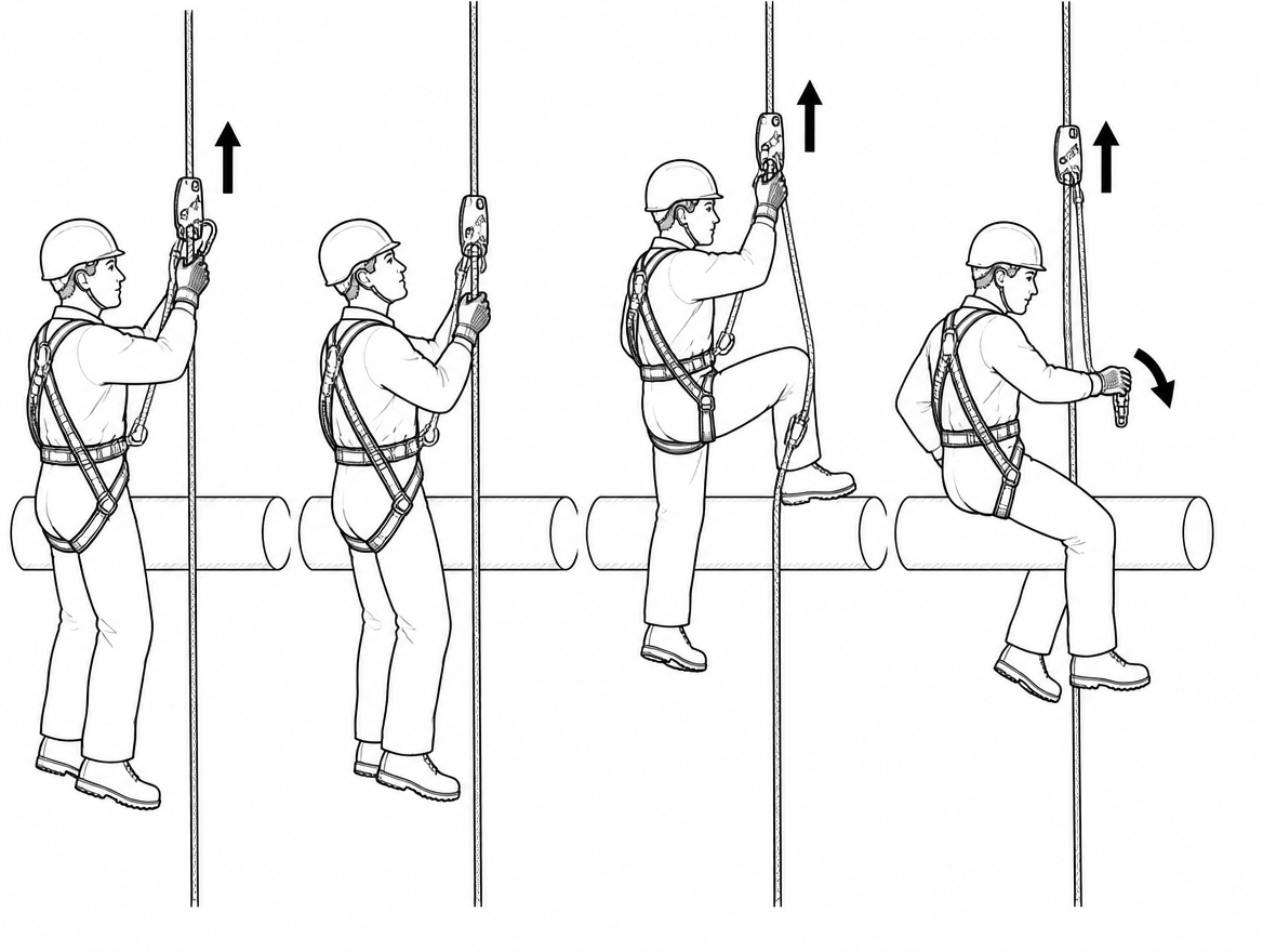
Re-belays and deviations in rope access
On a two-rope system, a re-belay is passed one rope at a time. The user descends until the re-belay knot reaches the descender, takes their weight on the lower section of the working rope by transferring the descender below the re-belay anchor, and only then moves the Type A back-up device from the upper section of the safety line to the lower section. At no point are both ropes disconnected. The back-up device is kept high on the safety line and clear of the descender’s operating hand so it cannot be accidentally held open.
A deviation is a lighter case: the rope is pulled aside rather than re-anchored, so the connector at the deviation is opened and closed around the rope while the user remains attached to both ropes throughout. What the deviation changes is the load direction and the swing potential — releasing a steep deviation without controlling it produces a pendulum, which is a hazard in its own right even with a sound attachment.
Both manoeuvres are training-dependent. They belong to personnel who have been trained and assessed on that specific technique and equipment, working within an ISO 22846 style rope access regime with a supervisor present, not to a general climbing team that happens to own a rope grab.
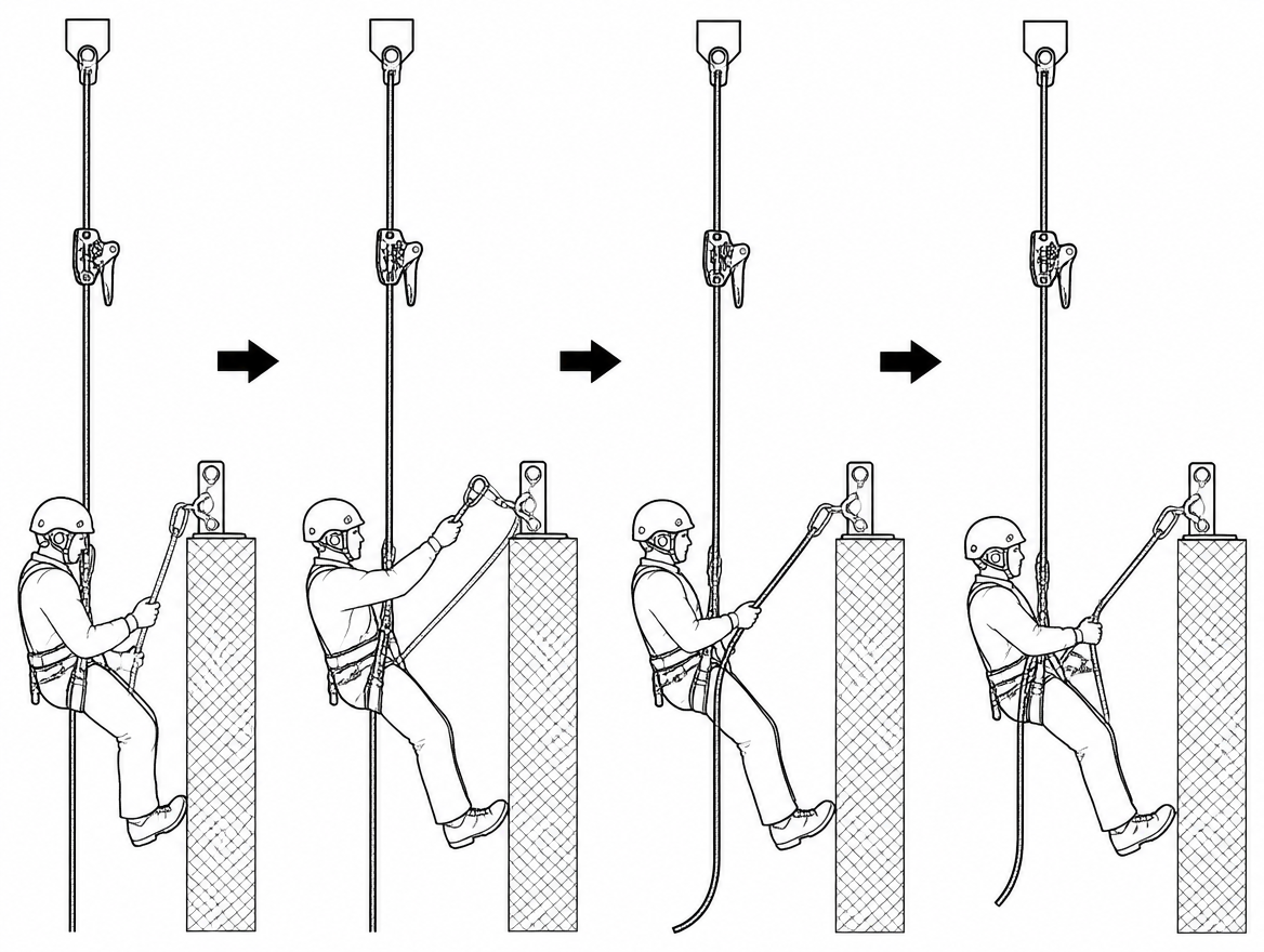
Failure modes to design out before the job starts
- Opening the only device. The default failure. It is prevented by equipment selection and a briefed sequence, not by care.
- Slack above the device. A rope grab pushed above the head or left with a loose loop of line increases fall distance and can turn a controlled arrest into a swing. Keep the device tracking with the body.
- Gripping the device during a slip. A hand clamped on the device body can prevent the locking element from engaging. Train the reflex of releasing the device and grabbing the structure or rope, not the device.
- The back-up device left too low. On the safety line, a low back-up device means a longer fall and a higher risk of contact with a re-belay anchor or the structure.
- Wrong rope, right device. A device outside its certified diameter range, or on a rope of a different construction from the one it was tested with, may slip or fail to lock. Diameter and rope type are specification, not preference.
- No clearance calculation at the obstacle. Required clearance below the user is stated by the manufacturer for each device and anchor line combination and includes device travel, connector extension, harness stretch and a safety margin. Re-check it at the point where the obstacle sits, not just at the top of the drop.
- No rescue provision. A worker stuck at a jammed device or suspended after an arrest needs recovery in minutes. The rescue method, the equipment for it — including any descender used for rescue to EN 341 — and the trained people to operate it are part of the plan, not a call to the emergency services.
Inspection and documentation that make the pass reliable
Obstacle passing depends on hardware that is in specification. EN 365 sets the framework for the information the manufacturer must supply, for marking, and for periodic examination by a competent person at intervals not exceeding 12 months — more frequently where use, environment or legislation demand it. For an obstacle pass, three checks are worth calling out specifically:
- Pre-use check of the device and the line — free movement of the locking element, no wear or deformation, no contamination, correct orientation marking present and legible on the device body.
- Inspection of the anchor line and its brackets or intermediate anchors — alignment, corrosion, fixings, and rope condition at every point where the line changes direction or bears on an edge.
- Anchor documentation — anchor devices to EN 795, with the additional considerations of CEN/TS 16415 where more than one person may load the same anchor, and records showing the installation and its last examination.
Under an ISO 45001 management system, this is where the procedure becomes auditable: the method statement names the obstacle, names the system, names the pass technique, and names the trained personnel authorised to perform it.
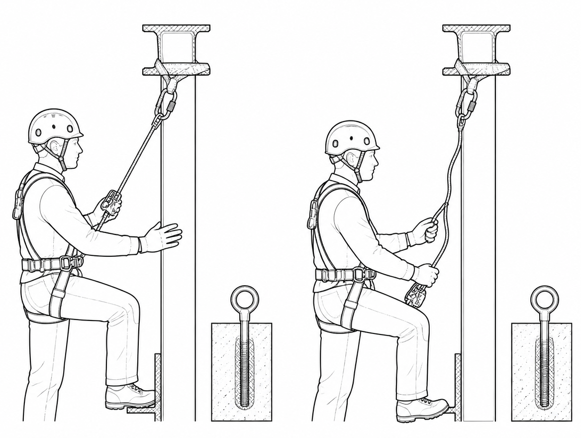
The decision in one sequence
- Survey the line and list every obstacle by type before anyone climbs.
- Ask first whether the obstacle can be removed by re-rigging. If it can, remove it.
- If it stays, confirm in the manufacturer’s instructions whether the device is designed to pass it.
- If it is not, provide a second independent attachment and a stable stance at the obstacle.
- Brief the sequence — attach, check, load, then release — and confirm the rescue method and required clearance at the obstacle.
- If none of the above can be satisfied, the line is not fit for use as rigged. Re-rig it or change the access method.
Next step: review the manufacturer’s instructions for the specific fall arrester and anchor line on your site against the obstacle list above, and confirm whether your system is certified to EN 353-1, EN 353-2 or EN 12841 — that single answer determines every obstacle procedure that follows.
Frequently asked questions
What counts as an obstacle on a vertical line?
An obstacle is anything on or beside the anchor line that stops a guided type fall arrester from travelling freely. In practice this includes intermediate anchor brackets on a rigid anchor line, re-belays and intermediate anchors on a rope, deviations that pull the rope sideways, mid-line or joining knots, structural interference such as cable trays, brackets, tie-backs, guardrail returns, platform cut-outs and pipework, and edges or transitions where the line changes direction. Each has a different solution, and treating them as one generic obstacle is where planning usually fails.
What is the governing rule for passing an obstacle with a rope grab?
A personal fall protection system under EN 363 only protects the user while it is connected, so the controlling principle is that the second attachment is made before the first is released. Opening the device and lifting it over the obstacle means that, in that instant, the fall arrest system does not exist.
What are the legitimate ways to satisfy continuity of attachment?
There are only three: the device is designed to pass the obstacle (typically a guided type fall arrester on a rigid anchor line to EN 353-1, where the intermediate brackets are shaped so the device passes through without being opened); a second, independent attachment carries the user during the transfer (two fall arresters on two lines, or a fall arrester plus a separate connecting device attached to a suitable anchor to EN 795); or the obstacle is removed from the system before the user goes on the line, by re-rigging the rope, repositioning the deviation, or replacing the line with one that has no mid-line knot.
Can an EN 353-2 flexible anchor line system pass a knot or intermediate anchor?
Most EN 353-2 systems have no provision for passing an intermediate anchor or a knot. The device may only be used with the anchor line type, construction and diameter specified by the manufacturer, and usually with the manufacturer's own terminations. If the drop cannot be rigged as a single clean line from top anchor to termination, an EN 353-2 system is the wrong choice for that job.
Why is obstacle passing a routine manoeuvre in rope access?
Rope access is the one context in which obstacle passing is a routine, taught manoeuvre, because the method rests on two independently anchored ropes. Under EN 12841, rope adjustment devices are classified as Type A (back-up device on the safety line), Type B (ascender on the working line) and Type C (descender on the working line). ISO 22846-1 and ISO 22846-2 set out the fundamental principles and code of practice, including the two-rope approach that makes a re-belay or deviation pass possible without ever leaving the user on a single point. EN 12841 devices are certified for a stated rope diameter range and are normally used with low-stretch kernmantle rope to EN 1891.
Need this as a document you can issue? The template library gives you the risk assessments, permits and inspection logs in editable form — and employer plans cover a whole team with completion records.