Safety / Tips and Tricks / Rope access and confined space
Activity 01 · Rope access
Rope Grab Behaviour in High Winds: What Changes, and How to Manage It
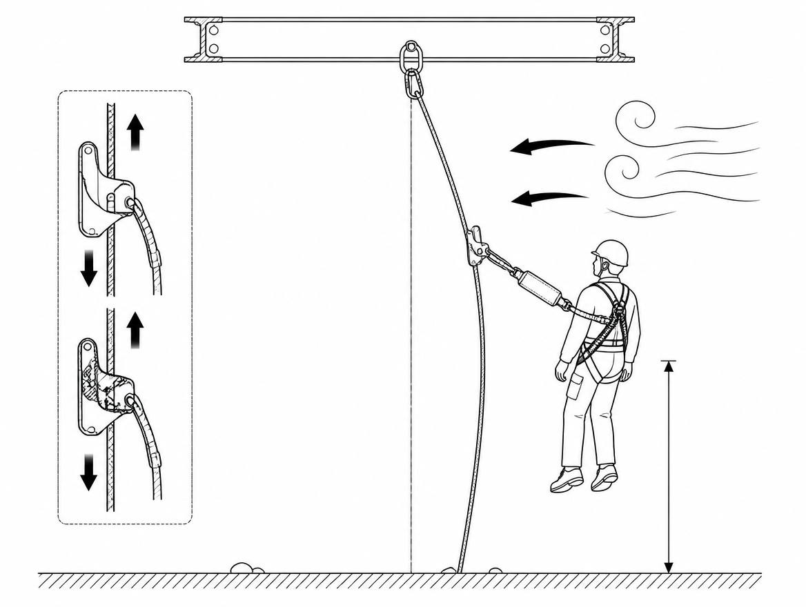
A guided type fall arrester — the device most people on site call a rope grab — is tested and certified on a line that hangs more or less straight, with the user moving broadly up and down it. Wind breaks both of those assumptions at once. It bows the anchor line out of the vertical, it pushes the user sideways so the device is loaded off its intended axis, and it can lift the bottom of the line so the tension the manufacturer relies on disappears. None of this shows up as a visible defect during a pre-use check, which is why wind-related problems with rope grabs tend to be discovered during an arrest rather than before one.
This article covers what actually changes in the device’s behaviour as wind speed rises, what to check, how to set a defensible wind limit, and when a rope-based system should be swapped for something else.
What a guided type fall arrester assumes about its anchor line
Guided type fall arresters including a flexible anchor line are covered by EN 353-2. Two points from that framework matter more in wind than in still air:
- The device and the line are certified as one system. The fall arrester is type-tested with a specific anchor line — a stated construction, diameter and set of terminations, commonly a low-stretch kernmantle rope to EN 1891. Fitting the device to a different rope, or extending a line with a knot or an added length, invalidates the certification. Improvised tensioning arrangements put in place because “the line was flapping” fall into the same category.
- The connecting element between device and harness is fixed by the manufacturer. The device attaches to the fall arrest attachment point of a full body harness to EN 361, using connectors to EN 362, and where an energy absorber to EN 355 is part of the assembly it is part of the certified configuration. Adding a lanyard to give more freedom of movement in gusty conditions directly increases free fall distance.
The line itself must be attached to an anchor that suits the loads involved — typically an anchor device to EN 795 or a structural anchor verified by a competent person. Wind loading on the line and on the user is transferred into that anchor, and not always in the direction the anchor was chosen for.
Five ways wind changes rope grab behaviour
1. Lateral deflection of the anchor line
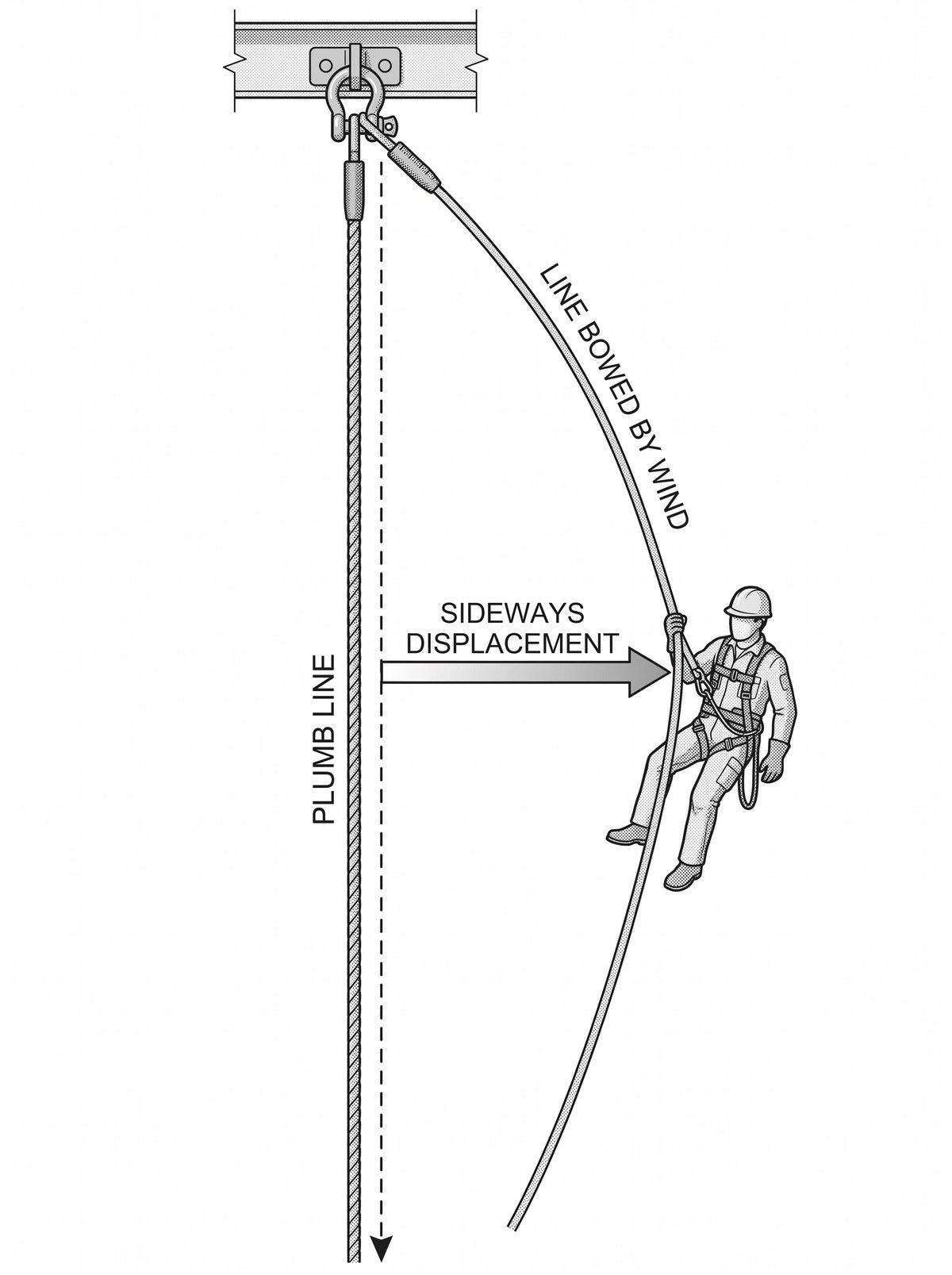
A suspended rope presents a small but real sail area over its whole length. In sustained wind it takes up a curve, displaced downwind, and the top section — nearest the anchor — deflects least while the mid-span deflects most. Two consequences follow. First, the user is no longer directly below the anchor, so any fall becomes a pendulum rather than a straight drop. Second, the device now sits on a line that curves away beneath it, so the geometry between cam, line and connector is no longer the geometry the device was tested with.
The practical marker on site is simple: if the line is not hanging close to plumb when unloaded, the system is already operating outside the condition it was designed around.
2. Off-axis loading from the user acting as a sail
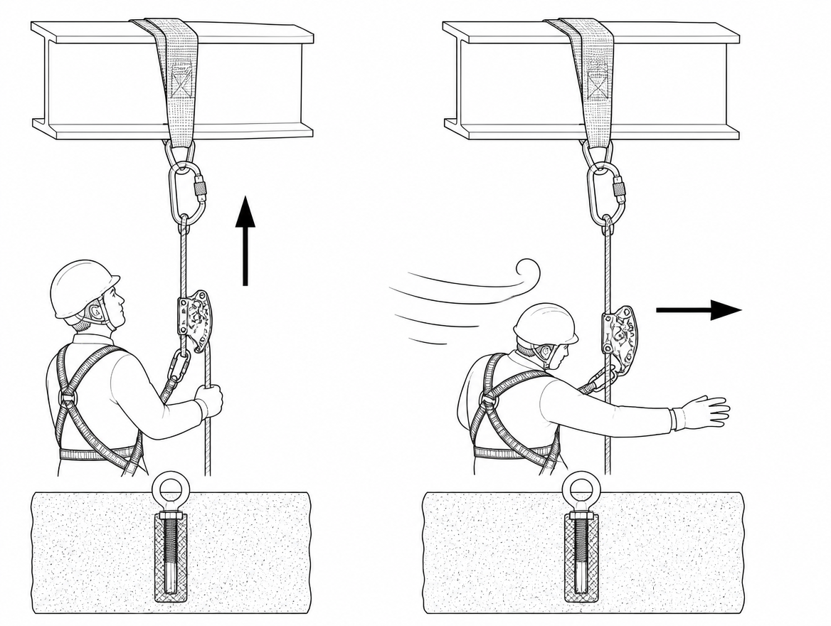
A person in full PPE, carrying tools or handling a panel, sheet or membrane, presents a substantial sail area. Wind pushes that mass downwind and the reaction is taken through the connecting element into the fall arrester. Guided type fall arresters are designed to lock when loaded along the line; loaded at an angle, the cam can be forced against the rope in a way that promotes premature or nuisance locking, and the connector may be loaded across its minor axis instead of along its major axis. Nuisance locking is the visible symptom and it has a predictable second-order effect: users start holding the device open, or push it up and down with a hand on the housing, which is precisely the manual override the design depends on not happening.
Handling large flat loads at height in wind is the highest-risk version of this. A single sheet of decking or cladding can generate more lateral force than the user can resist, and the fall arrest system will not prevent the loss of balance — it will only catch what follows.
3. Line oscillation and abrasion at contact points
Gusty rather than steady wind sets a free-hanging line oscillating. Over a shift this does two things. It works the device up or down the line in small increments where the manufacturer’s design allows free travel, so the device is not always where the user last left it. And it drags the rope repeatedly across whatever it touches — a slab edge, a purlin, a scaffold tube, a sharp flashing. Sheath abrasion from wind-driven contact is a common finding on lines used outdoors, and a rope with a damaged sheath at the point where the cam has to grip is a compromised system. Edge protection at every contact point is not optional once the line is moving.
4. Loss of tension at the base of the line
Many EN 353-2 systems require the lower end of the anchor line to be tensioned — by a specified weight, a tensioner, or a bottom anchor — because the device relies on the line being straight and reasonably taut to engage as tested. Wind acts against this in two ways: it lifts the lower section of the line, and where a weight is used it can swing that weight into the structure so it hangs up on a projection and stops applying tension at all. A line that was correctly tensioned at 07:00 in still air may be slack by mid-morning. Base tension is therefore a re-check item during the shift in windy conditions, not only at set-up.
5. Water, ice and contamination
High winds usually arrive with weather. A saturated kernmantle rope behaves differently from a dry one, a glazed or frozen line changes the friction available to the cam, and wind-driven dust, cement, sand or de-icing salt embedded in the sheath acts as an abrasive inside the device. Manufacturer instructions supplied under EN 365 state the environmental limits for the specific system, including whether it may be used on a wet or iced line. Those limits are product-specific and should be read for the device actually in use rather than assumed from experience with another model.
Required fall clearance grows before anything looks wrong
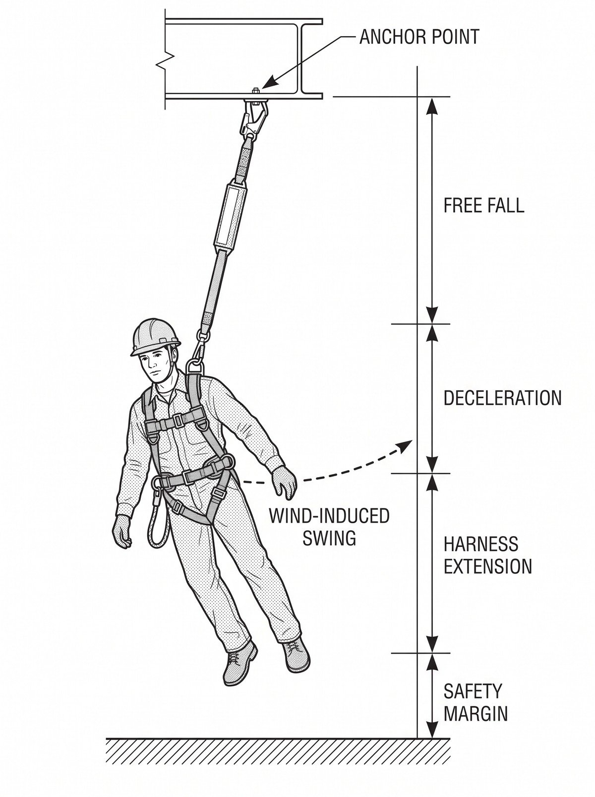
Clearance below the user is the calculation most affected by wind, and it changes without any visible warning. The clearance figure stated by the manufacturer is built from the free fall distance permitted by the device and connecting element, the deceleration distance as the device engages and any energy absorber deploys, harness extension and user displacement, plus a residual safety margin.
Wind adds to that stack in three ways:
- Slack introduced by line deflection. A bowed line means the distance the device travels before it engages can exceed the still-air case.
- Pendulum travel. With the user displaced downwind of the anchor, arrest is followed by a swing, and the lowest point of that swing arc is below the point of arrest. The swing also introduces a risk of striking structure or plant to the side of the fall line, which no amount of vertical clearance addresses.
- Added lanyards. Any element added to reach a work position in awkward, wind-affected conditions increases free fall and therefore clearance directly.
The correct response is to recalculate clearance for the wind-affected geometry using the manufacturer’s stated figures for the specific device, not to apply a general rule of thumb. Where the recalculated clearance is not available — a low working height, plant or stacked material below, a lower roof level — the rope-based fall arrest system is not a valid control for that task in that wind.
Measure wind where the work is, not where the site office is
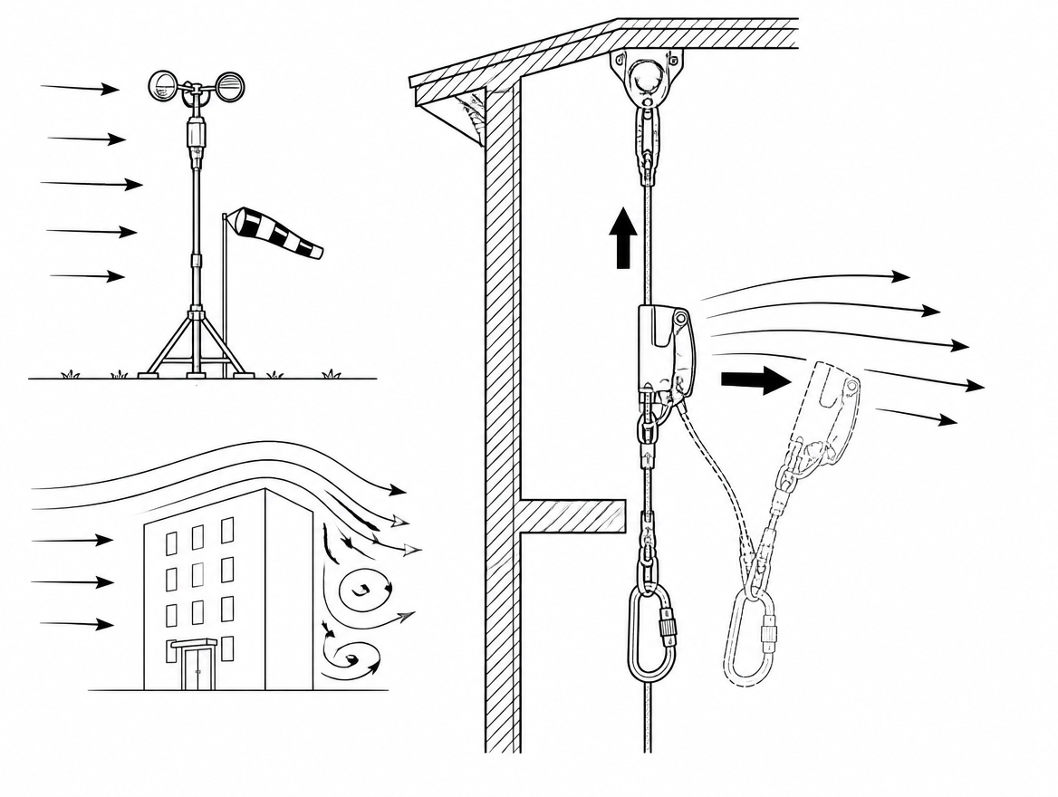
Wind speed generally increases with height above ground and accelerates around building corners, through gaps between structures and over parapets. A reading taken at ground level, or a regional forecast figure, systematically understates conditions at the work position. Two practices make the difference:
- Take the reading at the working position with a hand-held anemometer, and record gust as well as mean values. Gusts, not the mean, are what displace a person carrying a load.
- Know which limit binds first. The fall protection system, the access equipment and the load being handled each have their own limit, and the lowest one governs. Mobile elevating work platforms designed to EN 280 for outdoor use, for example, are designed against a specified wind speed — 12.5 m/s for outdoor machines — and an individual machine’s manual may state a lower figure. For reference, 12.5 m/s sits inside Beaufort force 6 (10.8–13.8 m/s).
Pre-use and in-shift checks specific to windy conditions
These sit on top of the normal pre-use inspection required by the manufacturer’s instructions under EN 365, not instead of it.
- Device orientation. Guided type fall arresters have a defined up/down orientation. An inverted device may travel freely and fail to engage. Confirm orientation each time the device is fitted to the line, including after the line has been moved to a new anchor.
- Line plumb and base tension. Check the line hangs close to vertical when unloaded and that the tensioning arrangement specified by the manufacturer is in place and free — not hung up on the structure, not resting on a surface, not removed.
- Contact points and edge protection. Follow the line from anchor to base looking for anywhere wind movement brings it against an edge. Inspect the sheath at those points for glazing, fuzzing or exposed core.
- Connector alignment. Confirm connectors to EN 362 are closed, locked, and free to align with the load direction rather than being cross-loaded against a harness attachment or the device housing.
- Nothing added. No additional lanyard, extension, knot or replacement rope. If the certified configuration will not reach the work position, the work method is wrong, not the equipment.
- Re-check during the shift. Base tension, line contact points and wind readings all change through the day. Build a re-check into the shift rather than relying on the morning inspection.
Setting a wind limit that holds up
The weakest arrangement is one where the decision to stop is left to the individual on the line at the moment conditions get bad — late in the task, with the work nearly finished. A defensible limit has four features:
- A number, not an adjective. A stated mean and gust value in m/s, derived from the manufacturer’s limits for the fall protection and access equipment, the sail area of the material being handled, and the exposure of the position.
- A named measurement method and location. Which instrument, read at which position, at what interval.
- A named person who calls the stop and a defined action when the limit is reached — secure loose material, descend, stand down the task.
- A review trigger when conditions or methods change. Under ISO 45001, operational planning and control (clause 8.1) includes managing change; a change of material, working height, anchor position or access method is a change to the wind assessment, not just to the work plan.
When a rope grab is the wrong answer for windy work
Fall arrest is the last option in the hierarchy for work at height, and wind is a strong argument for moving up that hierarchy rather than tuning the arrest system:
- Restraint instead of arrest. A correctly configured work restraint system that physically prevents the user from reaching the fall edge removes the fall, the pendulum and the clearance problem together. This requires a fixed-length restraint lanyard and an anchor position chosen so the edge cannot be reached — not an adjustable lanyard used at maximum length.
- Collective protection. Edge protection or a scaffold with a working platform is unaffected by the geometry problems described above, and it protects everyone on the level rather than only the person clipped in.
- A rigid guided system. Where a permanent vertical access route is being installed, a guided type fall arrester on a rigid anchor line to EN 353-1 does not deflect, oscillate or lose tension in wind. It is a design decision rather than a same-day fix, but it is the right one for exposed masts, ladders and towers used routinely.
- Rescheduling. Deferring the lift, the sheet handling or the inspection to a calmer window is a legitimate engineering control, and is usually cheaper than the alternative.
After a windy shift, and after an arrest
Any component of a fall arrest system that has arrested a fall must be withdrawn from use immediately and not returned to service unless the manufacturer’s instructions permit it following examination by a competent person. Beyond that, wind exposure specifically justifies a closer look at the anchor line: sheath abrasion at contact points, glazing from repeated dragging, and deformation or contamination of the device housing and cam. Under EN 365, periodic examination by a competent person is required at intervals stated by the manufacturer and at least every 12 months, and more frequent examination is appropriate for equipment used in abrasive or heavily exposed conditions. Record the wind conditions equipment has been used in — it is the information the examiner needs and the information nobody remembers six months later.
The short version
Wind does not usually break a rope grab; it changes the geometry the rope grab needs in order to work. A line that is not plumb, a base tension that has been lifted or hung up, a user displaced downwind, and a clearance figure calculated for still air are the four conditions to look for. Where any of them is present, either restore the certified configuration or change the control — restraint, collective protection, a rigid guided system, or a different day.
Next step: pull the manufacturer’s instructions for the specific EN 353-2 system in use on your site, find the stated required clearance, the anchor line specification and the base tensioning requirement, and check those three figures against how the system is actually rigged on the exposed elevations.
Frequently asked questions
Why do wind problems with rope grabs often go unnoticed during a pre-use check?
Because none of the wind-related effects show up as a visible defect. The line bowing out of plumb, off-axis loading, oscillation and loss of base tension are conditions of use rather than damage, which is why wind-related problems with rope grabs tend to be discovered during an arrest rather than before one.
Can I fit my rope grab to a different rope or extend the anchor line?
No. The device and the line are certified as one system: the fall arrester is type-tested with a specific anchor line of stated construction, diameter and terminations, commonly a low-stretch kernmantle rope to EN 1891. Fitting the device to a different rope, or extending a line with a knot or an added length, invalidates the certification, and improvised tensioning arrangements put in place because the line was flapping fall into the same category.
What does lateral deflection of the anchor line do to a fall?
A suspended rope presents a small but real sail area over its whole length, so in sustained wind it takes up a curve displaced downwind, deflecting least near the anchor and most at mid-span. The user is then no longer directly below the anchor, so a fall becomes a pendulum rather than a straight drop, and the geometry between cam, line and connector is no longer the geometry the device was tested with. The site marker is simple: if the unloaded line is not hanging close to plumb, the system is already outside its design condition.
Why is nuisance locking in wind more than an inconvenience?
Guided type fall arresters are designed to lock when loaded along the line. Loaded at an angle, because wind pushes the user or a flat load downwind, the cam can be forced against the rope in a way that promotes premature or nuisance locking, and the connector may be loaded across its minor axis instead of along its major axis. The predictable second-order effect is that users start holding the device open or pushing it along with a hand on the housing, which is precisely the manual override the design depends on not happening.
How often should base tension be checked in windy conditions?
Many EN 353-2 systems require the lower end of the anchor line to be tensioned by a specified weight, a tensioner or a bottom anchor, because the device relies on the line being straight and reasonably taut to engage as tested. Wind can lift the lower section of the line or swing a tensioning weight into the structure so it hangs up on a projection and stops applying tension. A line correctly tensioned at 07:00 in still air may be slack by mid-morning, so base tension is a re-check item during the shift, not only at set-up.
Need this as a document you can issue? The template library gives you the risk assessments, permits and inspection logs in editable form — and employer plans cover a whole team with completion records.