Safety / Tips and Tricks / Rope access and confined space
Activity 01 · Rope access
Horizontal Life-Line Installation: Planning, Anchorage and Commissioning to EN 795 Type C
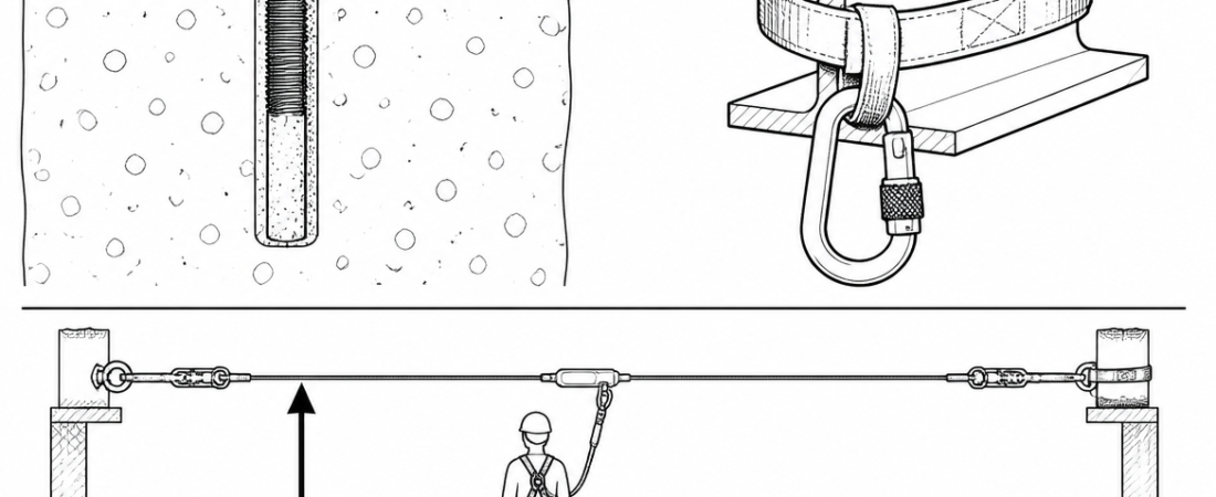
A horizontal life-line is only as good as the structure it is bolted to and the clearance under it. Most of the work in a compliant horizontal life-line installation happens before any cable is unrolled: confirming that the host structure can take the reaction forces, calculating the fall clearance including cable deflection, and fixing the line's route so that users can reach the work without a pendulum swing into plant or an edge. This article sets out the design inputs, the installation sequence, the commissioning evidence, and the examination regime that keeps a system in service.
What EN 795 Type C actually covers
EN 795:2012 classifies anchor devices into types. A horizontal life-line is a Type C anchor device: an anchor device using a flexible anchor line (normally stainless steel wire rope) that deviates from the horizontal by no more than 15°. A rigid horizontal rail is Type D. Single-point structural anchors are Type A, transportable deadweight anchors Type E, and Type B covers transportable devices such as beam anchors and temporary systems.
Two scope points matter on site:
- Number of simultaneous users. EN 795:2012 addresses devices for a single user. Where a line is to be used by more than one person at the same time, the reference document is CEN/TS 16415:2013, and the manufacturer’s certification must state the number of users the configuration was tested for. Adding a second user to a line certified for one is a change of system, not a judgement call.
- Conformity route. Under Regulation (EU) 2016/425, Types B and E are handled as personal protective equipment. Types A, C and D are permanently installed and treated as part of the structure, so a Type C line is not verified by a PPE certificate alone. Verification rests on two documents: the manufacturer’s test evidence for that specific configuration (span, sag, absorber, user count), and a structural assessment of the host structure at every fixing point, produced for that building.
Before designing the line: is fall arrest the right control?
ISO 45001:2018 clause 8.1.2 sets out the hierarchy of controls, and Directive 2009/104/EC on work equipment gives priority to collective protection for temporary work at height. A life-line is a fall-arrest or restraint control — it accepts that the worker can reach the hazard. Where the same access can be resolved with a permanent guardrail to EN 14122-3 or a fixed walkway, that solution removes the need for a harness, a clearance calculation and a rescue plan at the same time.
Where a line is the right answer, decide early whether it will be used in restraint (lanyard length physically prevents the user reaching the edge) or fall arrest (the user can go over and the system arrests the fall). Restraint layouts are simpler, generate lower loads and need no fall clearance. They also require the lanyard length to be fixed and controlled, which is a management issue as much as a hardware one.
Design inputs to establish before installation
Route and reach
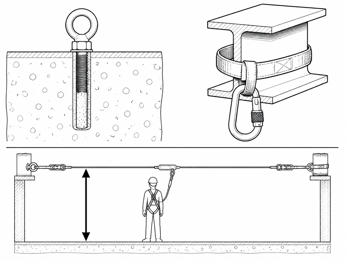
Set the line so the user’s working area is a defined zone either side of it, not an aspiration. The reachable area is a function of lanyard length and the user’s attachment point; obstructions, roof lights, and fragile panels sit either inside or outside that zone, and a line that runs too far from the work forces people to extend lanyards or unclip.
Span, sag and intermediate anchors
Intermediate anchors reduce cable deflection during a fall and limit the length of line loaded if one bracket fails. Certified spacing is set by the manufacturer’s test configuration and is commonly in the range of 10–15 m, with the total line length also limited. Longer spans mean more deflection, which directly increases the clearance requirement below the line.
Fall clearance
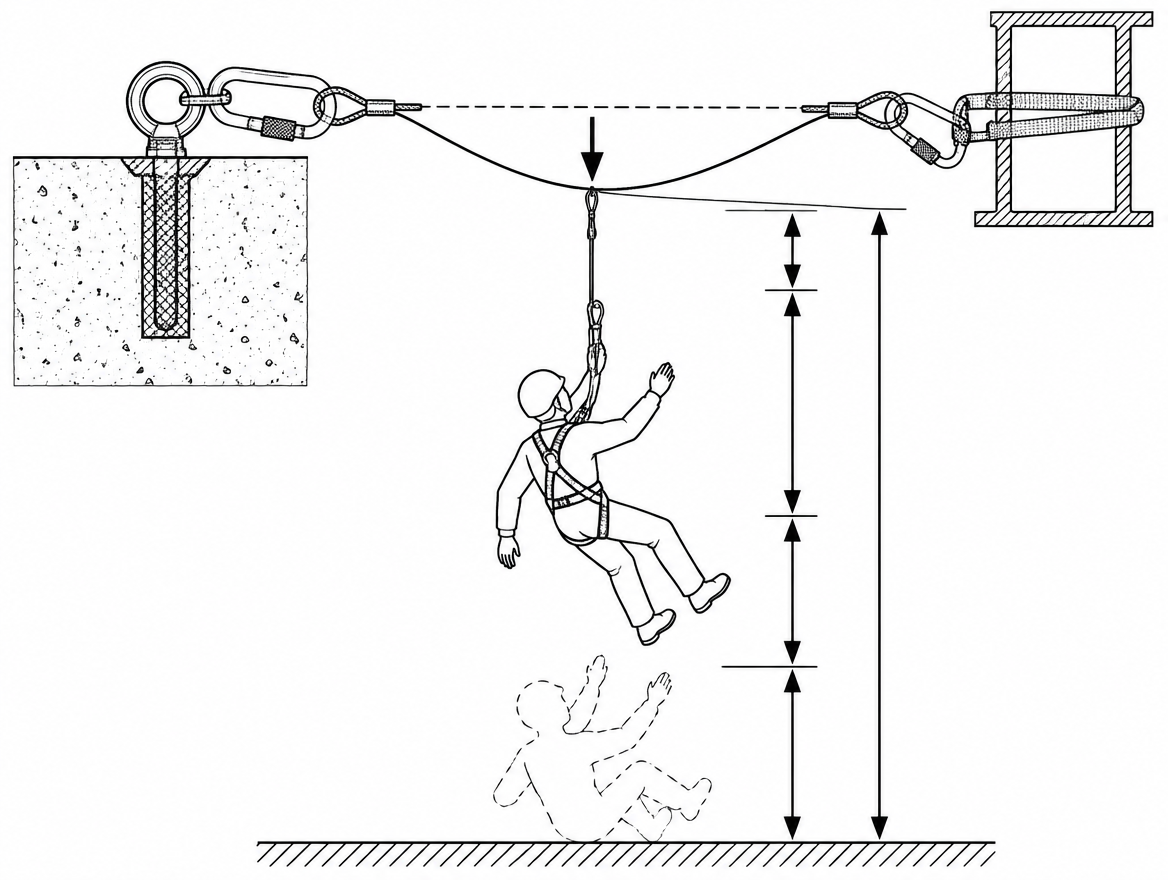
EN 355 limits the arrest force transmitted to the user to 6 kN and, in its dynamic test using a 2 m lanyard-and-absorber assembly, limits total arrest distance to 5.75 m. That is why manufacturers commonly quote around 6.75 m of clearance below a rigid anchor point — 5.75 m plus a 1 m residual margin. That figure already includes the assembly length and absorber deployment. On a flexible anchor line it does not include cable deflection, which must be added from the manufacturer’s span and sag data for the actual fall position.
| Element of the clearance stack | Source of the figure |
|---|---|
| Arrest distance of the lanyard and energy absorber | EN 355 dynamic test data / manufacturer’s instructions (EN 354 assembly length) |
| Deflection of the anchor line at the fall position | Manufacturer’s span, sag and user-count tables for the installed configuration |
| Displacement of the harness dorsal attachment | Manufacturer’s data for the EN 361 harness in use |
| Residual margin below the feet | Commonly 1 m; confirm against the manufacturer’s instructions |
Swing fall
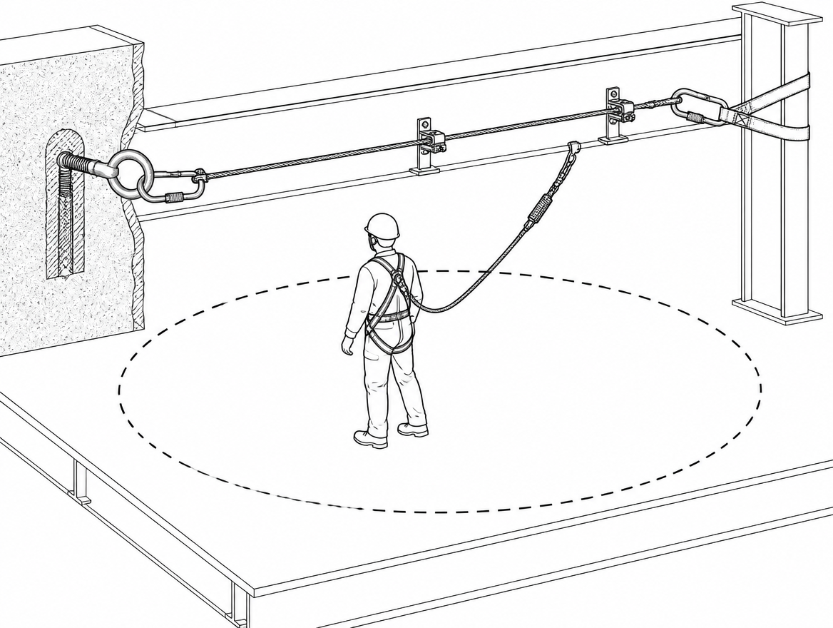
A user working well to one side of the line, or beyond the end of it, will pendulum on arrest. The consequence is impact with structure or a secondary fall, and the clearance calculation for a swinging fall is not the same as for a vertical one. Swing potential is controlled by line layout and by limiting the offset working angle, not by adding hardware after the fact.
Verifying the host structure: the step most often skipped
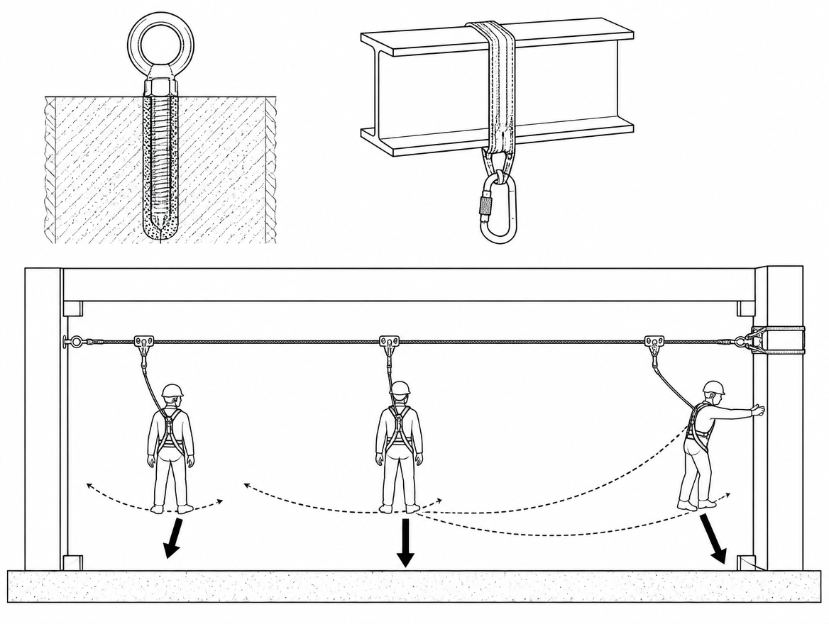
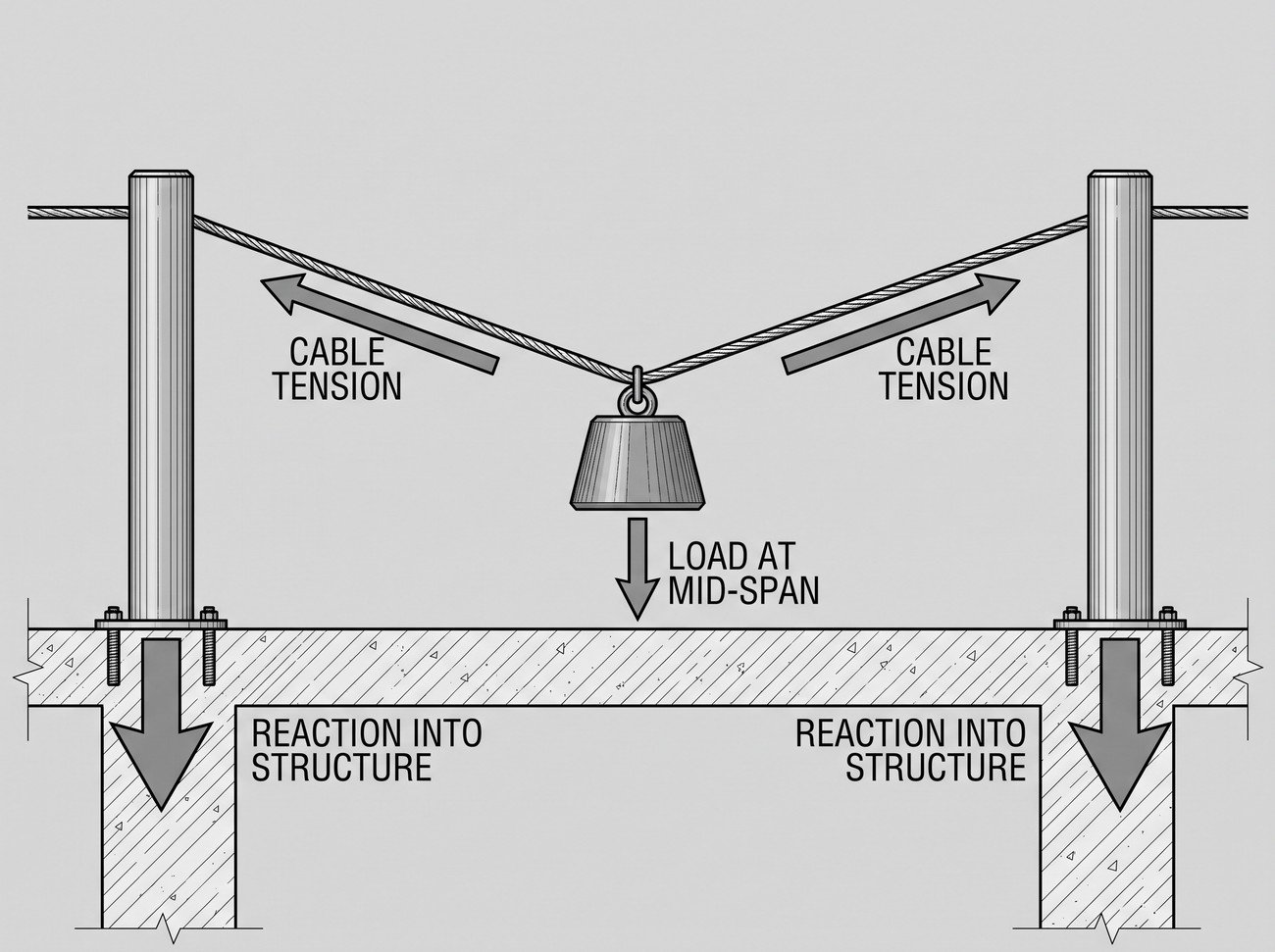
A tensioned line transfers a horizontal reaction into each end anchorage. Because the cable is close to horizontal, arrest loads are amplified at the ends; end anchorage reactions in certified configurations are frequently in the range of 8–12 kN, and the applicable figure comes from the manufacturer’s data sheet for that span, absorber and number of users. That figure, not a generic anchor test value, is the design load for the fixings and the structural check.
The structural assessment covers, for each fixing position:
- Substrate capacity. Concrete strength and reinforcement position for through-bolts or resin anchors; web and flange thickness for steel beam clamps; purlin section and span for roof-mounted posts.
- Load path. Where the reaction goes after it leaves the bracket. Timber rafters, composite panels and standing-seam sheets each have specific proprietary fixing methods; none of them accept an anchor designed for concrete.
- Pull-out testing. Post-installed anchors in concrete or masonry are normally proof-tested on site to the value specified by the anchor manufacturer, and the results recorded per fixing.
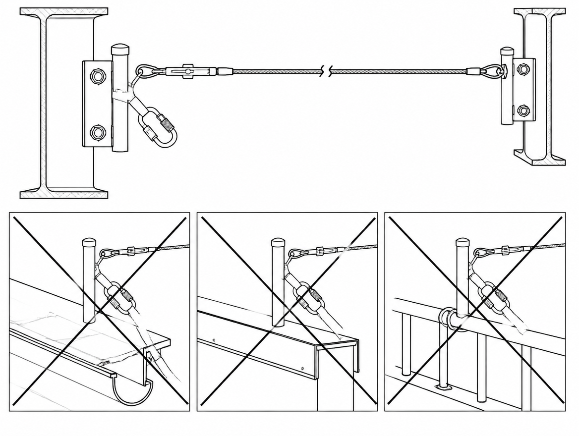
- Prohibited attachment points. Gutters, edge trims, fascia, roof lights, plant frames, cable trays, ductwork and handrails are not anchorage structures. Nor are guardrail posts, which are designed for a horizontal service load, not fall-arrest reactions.
Components and compatibility
A Type C system is certified as a complete assembly. Substituting a traveller, absorber, tensioner or termination from another manufacturer voids the test evidence, and travellers are frequently dimensioned for one specific cable diameter and bracket profile.
- Anchor line: commonly 8 mm stainless steel wire rope with factory-swaged or on-site swaged terminations, executed with the manufacturer’s tooling and dies.
- In-line energy absorber: limits the load transmitted to the end anchorages and the structure. Its presence and type are part of the certified configuration.
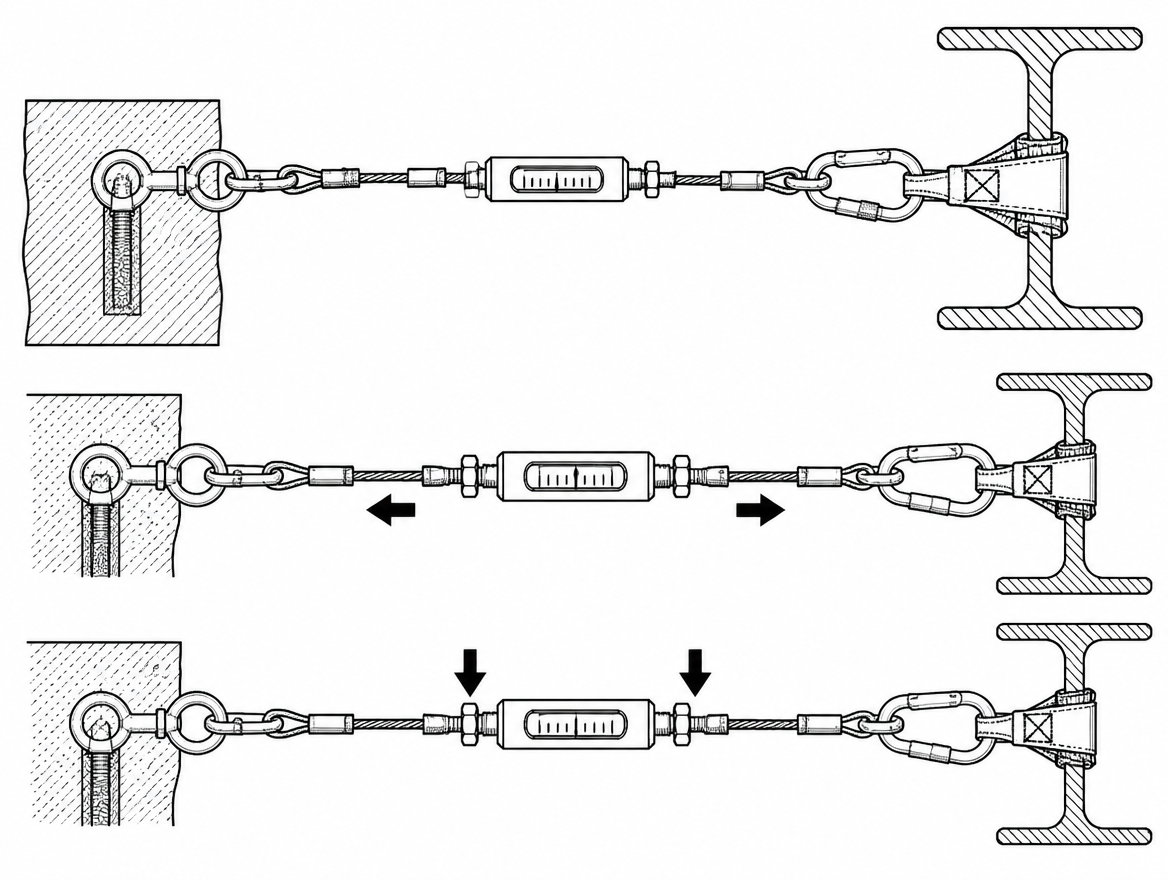
- Tensioner with tension indicator: the pre-tension is a specified value, set and verified with the indicator supplied — not adjusted by feel.
- Traveller: pass-through travellers cross intermediate brackets without disconnection. Where a traveller must be removed to pass an obstruction, the system is no longer continuous and the user needs a second connection point.
- User PPE: full body harness to EN 361 connected at the dorsal or sternal fall-arrest attachment; lanyard to EN 354 with energy absorber to EN 355, or a retractable type fall arrester to EN 360 where the manufacturer states it is compatible with the line; connectors to EN 362.
Installation sequence
- Set out the line from the approved design drawing, marking every post and bracket position, and confirm each position against the structural assessment before drilling. Deviations return to the designer.
- Protect the installers. The installation team is working at height without the system they are installing. Their own fall protection — existing anchors, MEWP, temporary Type B devices, netting — is planned as part of the job, not improvised.
- Install end anchorages first, to the manufacturer’s fixing pattern, torque values and sealing details. On roofs, weatherproofing of the penetration is part of the installation, and a failed detail becomes a leak that gets blamed on the safety system.
- Install intermediate and corner brackets at the certified spacing. Corners are configuration-specific: many systems require a dedicated corner component and a maximum deviation angle.
- Fit the anchor line, absorber and tensioner, swaging terminations with the specified tool and checking the swage dimensions against the instructions.
- Tension to the specified value using the tension indicator, then re-check after the line has settled.
- Function-test the traveller over the full length, including every intermediate bracket and corner, in both directions.
Commissioning, marking and handover
Installation ends with evidence, not with a tightened bolt. A handover pack for a Type C system normally contains:
- The as-installed drawing, showing line route, post and bracket positions, span lengths and number of permitted users.
- The structural assessment and any anchor pull-out test results, per fixing.
- The manufacturer’s declaration/certification for the installed configuration, plus the installer’s competency evidence.
- The fall clearance figure for each part of the line, and the maximum permitted lanyard configuration.
- User instructions, the rescue plan, and the record for the first periodic examination.
EN 795 requires the anchor device to be marked and to be supplied with instructions for use. In practice that means a durable, legible system identification at the point of access carrying the system reference, installation and next examination dates, and the number of users — and it means those instructions reaching the people who clip on, not just the facilities archive. A line whose identification has weathered to illegibility cannot be verified by a user at the hatch, which is a reason to take it out of use until it is re-marked.
Inspection and periodic examination
EN 365 sets the framework for inspection, periodic examination and records for fall-protection equipment and anchor devices:
- Pre-use check by the user, every time: system identification present and within date, cable free of broken wires and kinks, tension indicator reading correctly, posts and brackets undamaged and not loose, absorber not deployed, traveller running freely.
- Periodic examination by a competent person at intervals of no more than 12 months, with more frequent examination where the risk assessment, the environment or the manufacturer’s instructions require it. Coastal, chemical and chlorinated atmospheres are the usual triggers for a shorter interval; stainless components in a chlorine-rich environment are susceptible to stress corrosion cracking that is not obvious from the ground.
- After any fall arrest, the system is taken out of service immediately and not returned to use until examined against the manufacturer’s post-fall procedure. Deployed absorbers, loaded terminations and distorted brackets are replaced, not assessed by eye.
- Records for the system and for each examination are retained and available to the people using the line.
Galvanic pairings deserve a specific look at each examination: mixed stainless, aluminium and galvanised components in a wet roof environment corrode at the interface, and the damage concentrates exactly where load is transferred.
Rescue: part of the installation, not an afterthought
A suspended worker cannot be left hanging while a plan is invented. ISO 45001:2018 clause 8.2 requires emergency preparedness and response arrangements to be established and tested, and for a life-line that means a documented, rehearsed method of reaching and lowering a suspended person from every point on the line — with the equipment on site and the people trained to use it. If the only credible answer is the fire service, the response time, the access route and the vehicle position are checked before the system is signed off, not on the day.
Faults that recur on installed systems
- End anchorages fixed to non-structural elements — edge trim, gutters, plant frames — because the position suited the cable route.
- Clearance calculated for a rigid anchor point, with cable deflection omitted.
- Spans exceeding the certified configuration to save a bracket.
- Travellers, absorbers or connectors mixed between manufacturers.
- Tension set by hand and never verified against the indicator.
- Two or more users on a line certified for one.
- The line used as an anchorage for lifting, rope access, hauling or restraining materials.
- No system identification, no as-installed drawing, and no examination record — leaving users unable to confirm the system is fit for use.
The practical takeaway
Three figures govern a horizontal life-line installation, and all three come from documents rather than judgement: the end anchorage reaction from the manufacturer’s data for the installed configuration, the structural capacity at each fixing from a site-specific assessment, and the total clearance below the line with cable deflection included. Where any of the three is missing, the system is not commissioned — whatever is bolted to the roof. Next step for a system already in service: pull the handover pack, check the as-installed drawing against what is physically on the roof, and confirm the date of the last periodic examination against the 12-month maximum interval in EN 365.
Frequently asked questions
What makes a horizontal life-line a Type C anchor device under EN 795?
EN 795:2012 classifies a Type C anchor device as one using a flexible anchor line, normally stainless steel wire rope, that deviates from the horizontal by no more than 15°. A rigid horizontal rail is Type D, single-point structural anchors are Type A, transportable deadweight anchors are Type E, and Type B covers transportable devices such as beam anchors and temporary systems.
Can more than one person use a horizontal life-line at the same time?
Only if the configuration was certified for it. EN 795:2012 addresses devices for a single user; where a line is to be used by more than one person at the same time the reference document is CEN/TS 16415:2013, and the manufacturer's certification must state the number of users the configuration was tested for. Adding a second user to a line certified for one is a change of system, not a judgement call.
Is a PPE certificate enough to verify a Type C line?
No. Under Regulation (EU) 2016/425, Types B and E are handled as personal protective equipment, while Types A, C and D are permanently installed and treated as part of the structure. Verification of a Type C line rests on two documents: the manufacturer's test evidence for that specific configuration (span, sag, absorber, user count), and a structural assessment of the host structure at every fixing point, produced for that building.
Why is the commonly quoted 6.75 m of clearance not enough under a life-line?
EN 355 limits the arrest force transmitted to the user to 6 kN and, in its dynamic test using a 2 m lanyard-and-absorber assembly, limits total arrest distance to 5.75 m, which is why manufacturers commonly quote around 6.75 m below a rigid anchor point (5.75 m plus a 1 m residual margin). That figure includes the assembly length and absorber deployment, but on a flexible anchor line it does not include cable deflection, which must be added from the manufacturer's span and sag data for the actual fall position.
How are swing falls and end anchorage loads dealt with?
A user working well to one side of the line, or beyond the end of it, will pendulum on arrest, risking impact with structure or a secondary fall; the clearance calculation for a swinging fall is not the same as for a vertical one, and swing potential is controlled by line layout and by limiting the offset working angle rather than by adding hardware afterwards. Because the cable is close to horizontal, arrest loads are amplified at the ends, with end anchorage reactions in certified configurations frequently in the range of 8–12 kN, taken from the manufacturer's data sheet for that span, absorber and number of users.
Need this as a document you can issue? The template library gives you the risk assessments, permits and inspection logs in editable form — and employer plans cover a whole team with completion records.