
Safety / Tips and Tricks / Rope access and confined space
Activity 01 · Rope access
Working Near Sharp Edges and Hot Work: Sharp Edge Rope Protection That Actually Holds
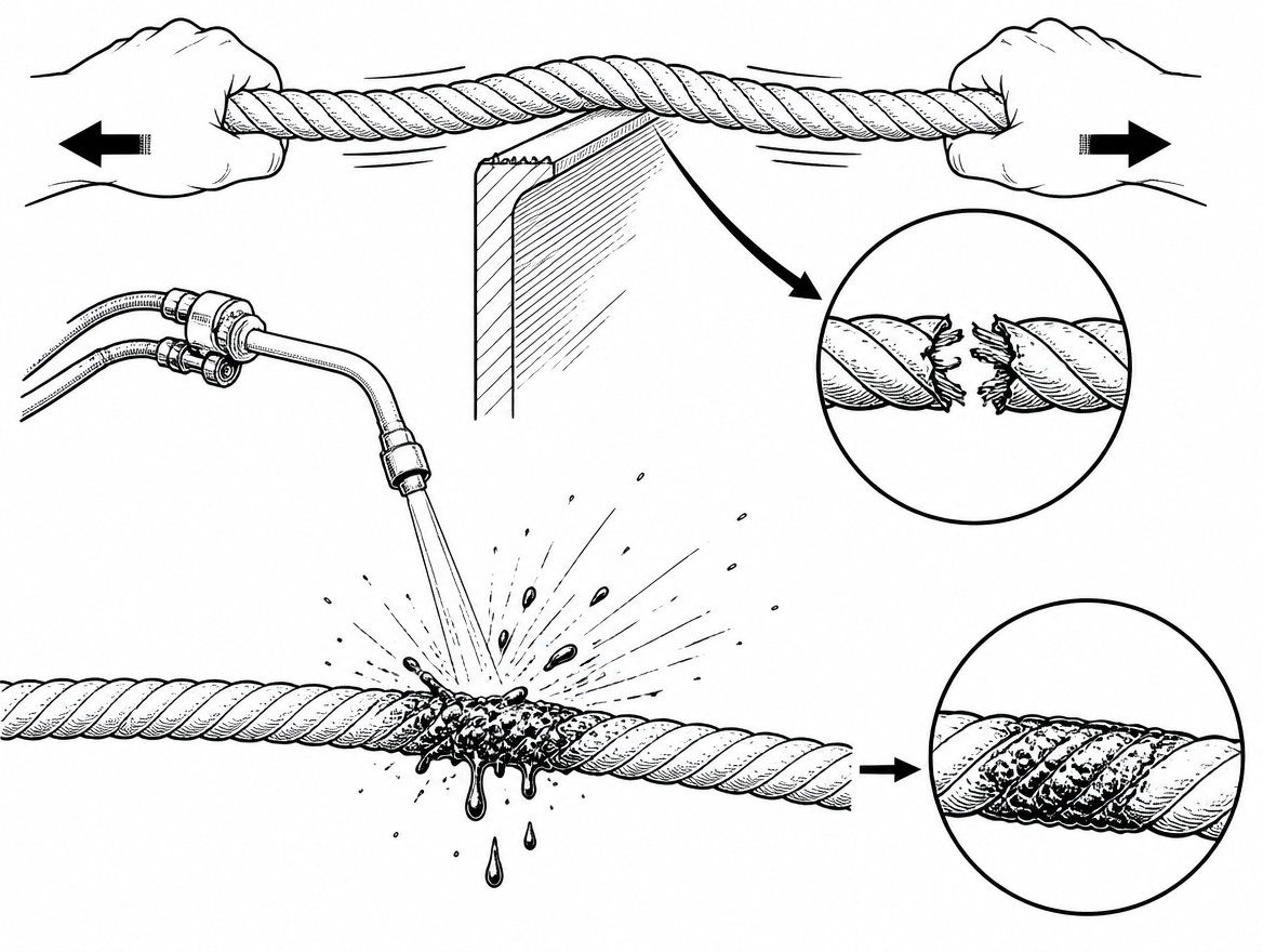
A rope that would hold well over 20 kN in a straight pull can be severed by a hand load if it is bent over a burred steel edge and moved sideways — and a single shower of oxy-fuel slag can glaze a sheath into a hard, brittle patch in under a second. Sharp edges and hot work are the two hazards most likely to destroy a load-bearing line while it is still under a worker. When both are present on the same job, as they routinely are during steelwork repairs, roof plant replacement or tank and vessel modification, the controls have to be planned together. This article covers how edges cut loaded ropes, how to build sharp edge rope protection that stays where it was put, what welding and cutting spatter does to synthetic fibre, and how to separate the two systems so that one incident cannot take out both lines.
Why an edge cuts a loaded rope so easily
Low-stretch kernmantle rope to EN 1891 Type A (10 mm to 16 mm diameter) is tested for static strength in a straight pull between terminations. None of that figure survives contact with a small-radius edge. Three things happen at once:
- Stress concentration. The whole load is carried by the fibres crossing the edge radius. A corner with a radius smaller than the rope diameter loads a narrow band of the sheath and the outer core yarns, not the full cross-section.
- Relative movement. Every ascent, descent, tool exchange or postural shift saws the rope across the corner. Sheath damage progresses from fuzzing, to broken bearer strands, to core exposure, sometimes within a single work period.
- Dynamic loading. A slip, a swing, or the arrest of a short fall applies a peak force at the exact point where the rope is already deformed over the corner. This is the mechanism behind most rope-over-edge failures, and it is why a backup line rigged over the same edge is not a backup at all.
Rolled steel, cut deck plate, glass fibre gutter trim, sheet-metal flashing, folded aluminium copings and freshly ground or flame-cut steel all count as sharp for this purpose. Freshly cut steel is the worst case: it combines a sharp arris with a burr and, during hot work, residual heat.
Deal with the edge in the right order: remove, protect, then cover
ISO 45001 requires the hierarchy of controls to be applied rather than defaulting to protective equipment, and the same logic applies literally here. The rigging solution is ranked, not optional.
1. Remove the rope-to-edge contact
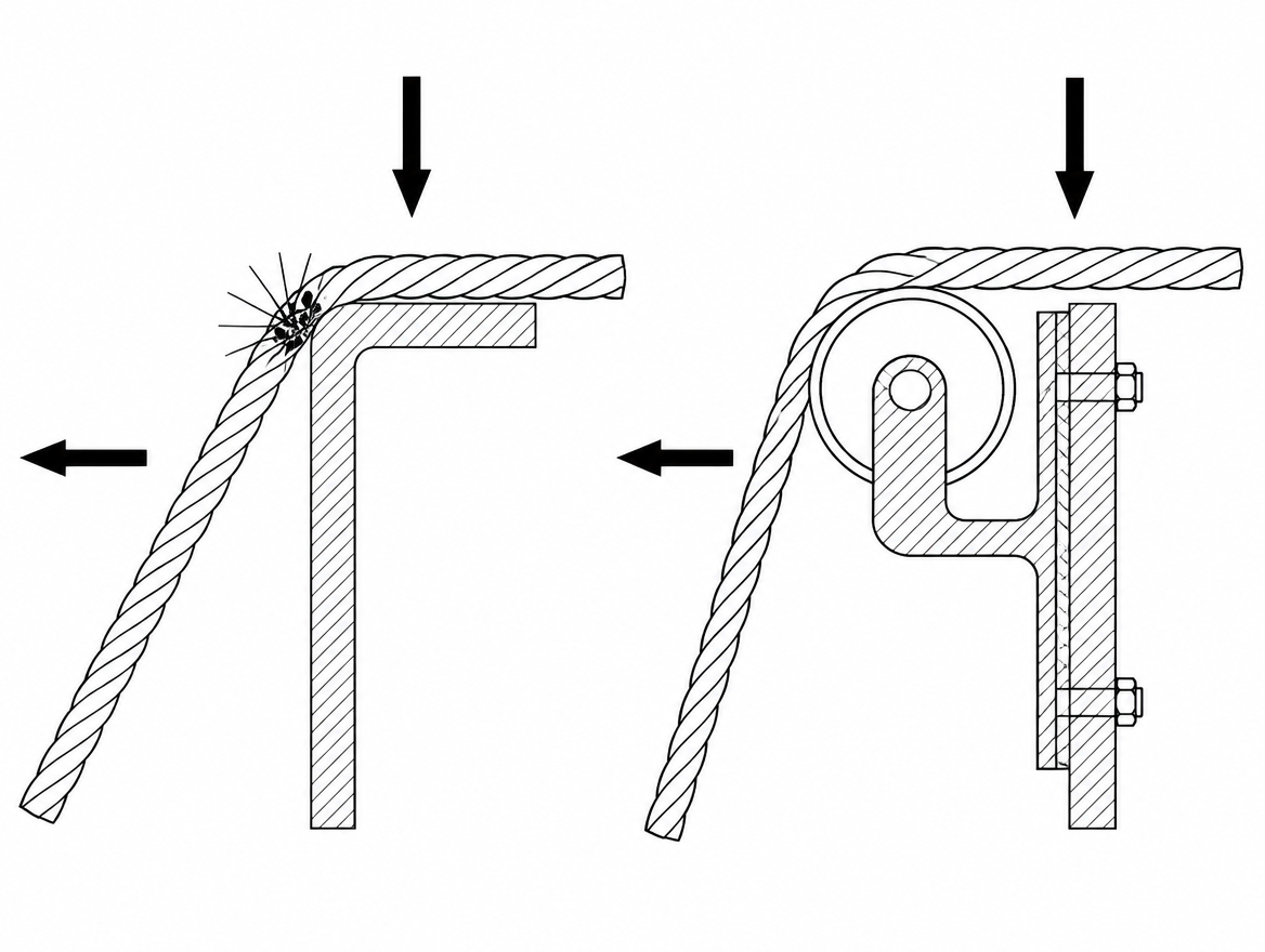
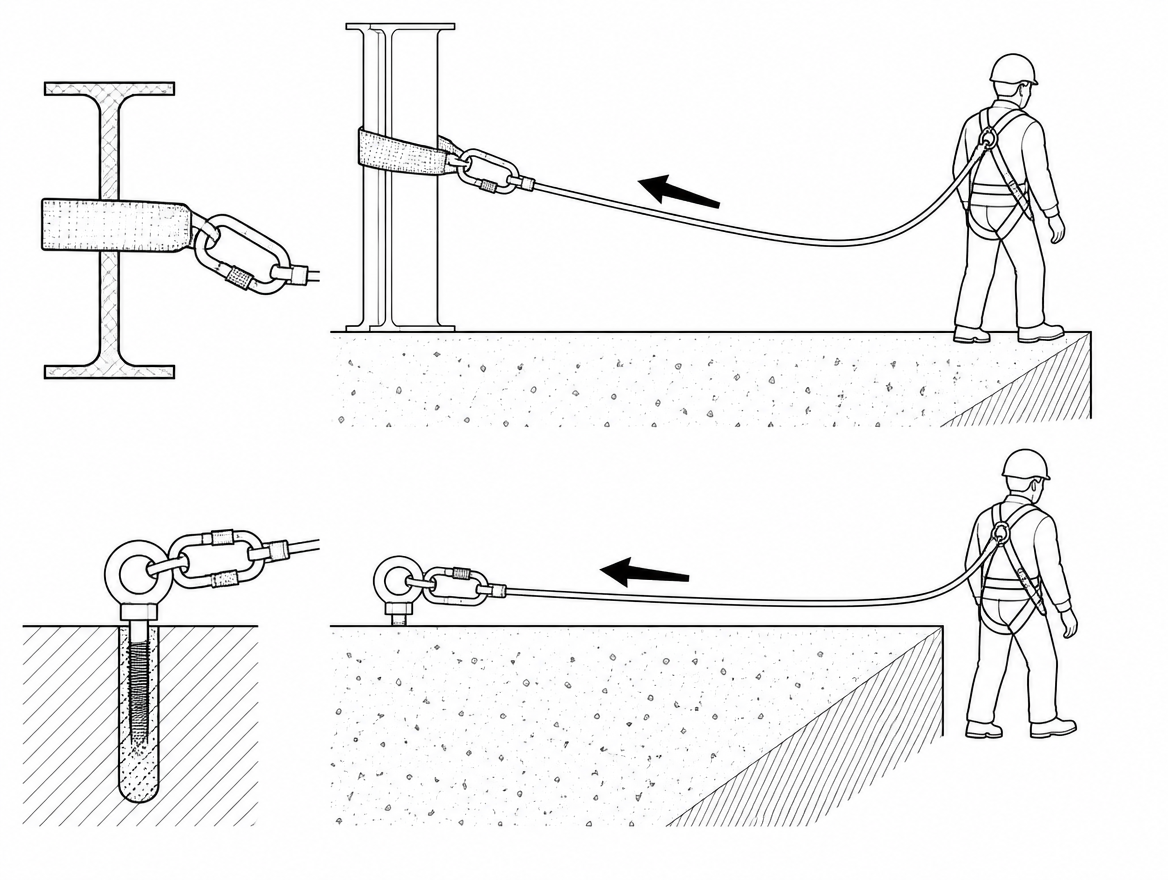
Re-rig so the rope never touches the edge. Options include moving the anchor back and higher so the line leaves the structure clear of the parapet, using a deviation to pull the line away from the face, or installing a re-anchor below the edge so the upper rope section is unloaded during work. Anchor devices used for this should conform to EN 795 (Types A to E, according to the installation), with CEN/TS 16415 applying where more than one person may load the same device. Structural anchors and their fixings need to be verified for the actual direction of pull created by a deviation — a redirect changes the resultant force on the anchor, often increasing it.
2. Protect the edge itself
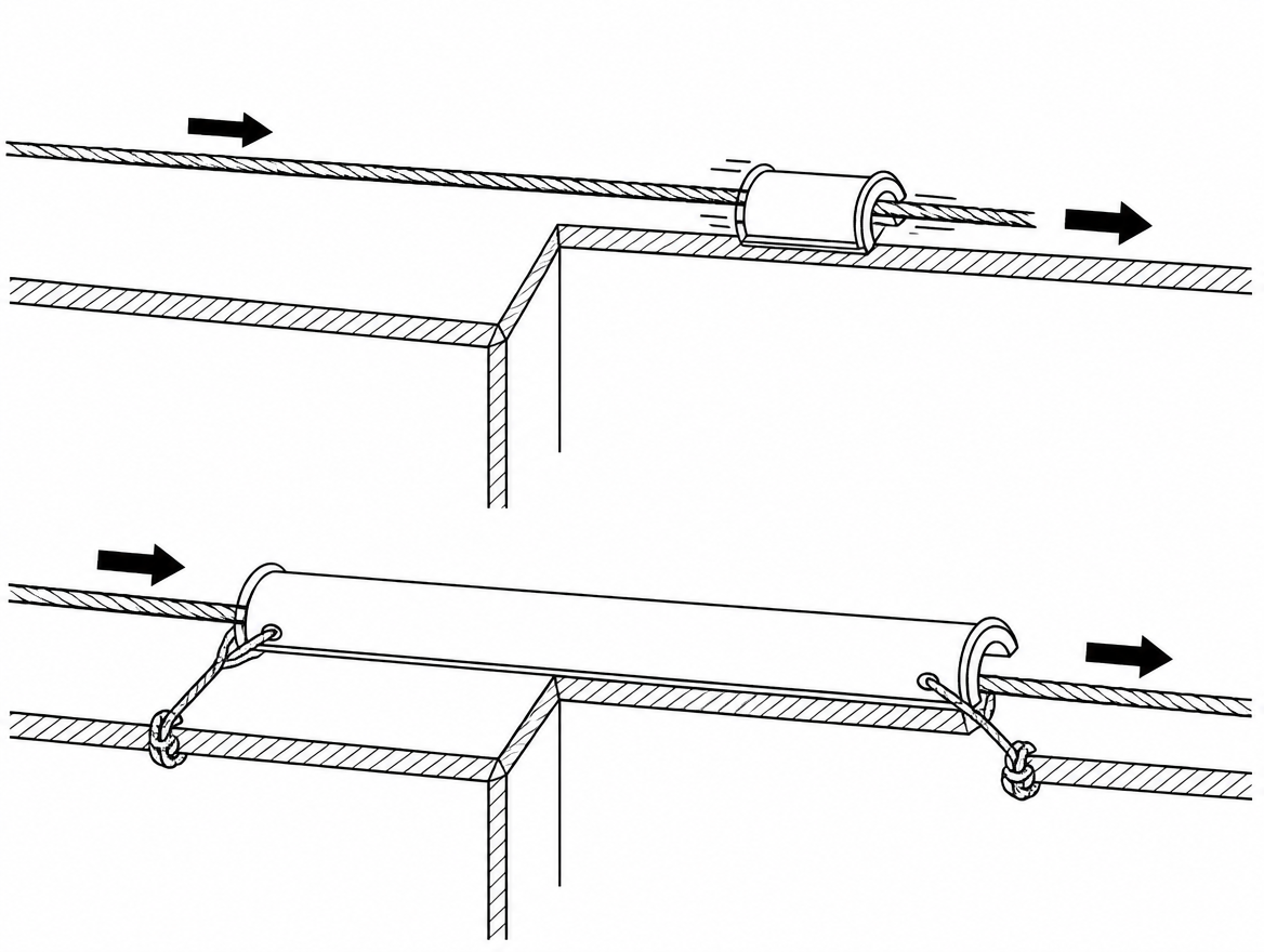
Where contact is unavoidable, change the edge, not just the rope. Edge rollers, rigid split-tube or channel protectors, purpose-made edge plates and radiused edge blocks give the rope a large bearing radius and stay fixed to the structure. Because they are attached to the building rather than the rope, they keep working while the rope moves under them — which is the normal condition during ascent and descent.
3. Cover the rope
Fabric rope protectors, sleeves and hose sections are the last line, not the first. They are useful over long, gently abrasive contact zones and for holding the rope off a rough surface, but they migrate with the rope unless independently restrained, and they hide the damage they are meant to prevent.
Note that a rope protector is not personal protective equipment in the same sense as the rope, harness or connectors, and there is no dedicated harmonised EN product standard for protectors comparable to EN 1891 for rope or EN 362 for connectors. Selection therefore rests on the manufacturer’s information and the site risk assessment: material, minimum bend radius delivered, resistance to the temperatures and contaminants present, and the method of attachment.
Fitting sharp edge rope protection so it stays in place
Most failures of edge protection are placement failures, not material failures. Practical requirements:
- Tie the protector back to the structure with a separate cord or strap, so rope movement cannot drag it off the edge. If the only attachment is to the rope, the protector travels with the rope and the edge is exposed at the worst moment.
- Cover the whole travel zone. The contact point migrates as the technician descends, as the rope stretches under load, and as the worker swings sideways. Protect a band, not a point.
- Protect the working line and the backup line separately. Two ropes running through one protector, over one corner, share one failure mode.
- Confirm placement from the top before loading, and confirm it again on each pass. Anyone at the anchor should be able to see that the rope is still bearing on the protector and not beside it.
- Check what is under the protector. Grit, weld spatter, swarf and broken glass trapped between the protector and the rope act as an abrasive.
Where a rope must remain in contact with a moving edge — a hoist beam, a rotating structure, a live crane path — sharp edge rope protection is not sufficient on its own. Stop the movement, isolate it, or re-rig.
What welding, cutting and grinding do to synthetic fibre
Ropes, slings and harness webbing in general access and rope access use are predominantly polyamide and polyester. Both are thermoplastic: strength falls progressively as temperature rises, well before any visible change, and the fibre melts in the region of a few hundred degrees Celsius — far below the temperature of welding spatter, oxy-fuel slag or grinding sparks, all of which arrive as discrete molten or incandescent particles. The result is a local fusion: a hard, glazed, often shiny spot where the fibres have lost mobility and become brittle. Aramid resists heat far better and chars rather than melts, but it is not a licence to run a line through a spatter shower.
Three consequences for planning:
- Damage is local and easy to miss. A single fused point a few millimetres across can be a rupture initiation site. It will not be found by looking at the rope from three metres away.
- Particles fall, bounce and travel. Slag from cutting falls the full height below the work and can lodge on ledges, in gutters, and on ropes rigged below the work position. Sparks from grinding are thrown in a broad cone in the direction the wheel is pointing.
- Heat and edges arrive together. The steel that has just been cut is both hot and sharp. Ropes, slings and lanyards must be kept off it until it has cooled and the arris has been treated.
Separating hot work from the fall protection system
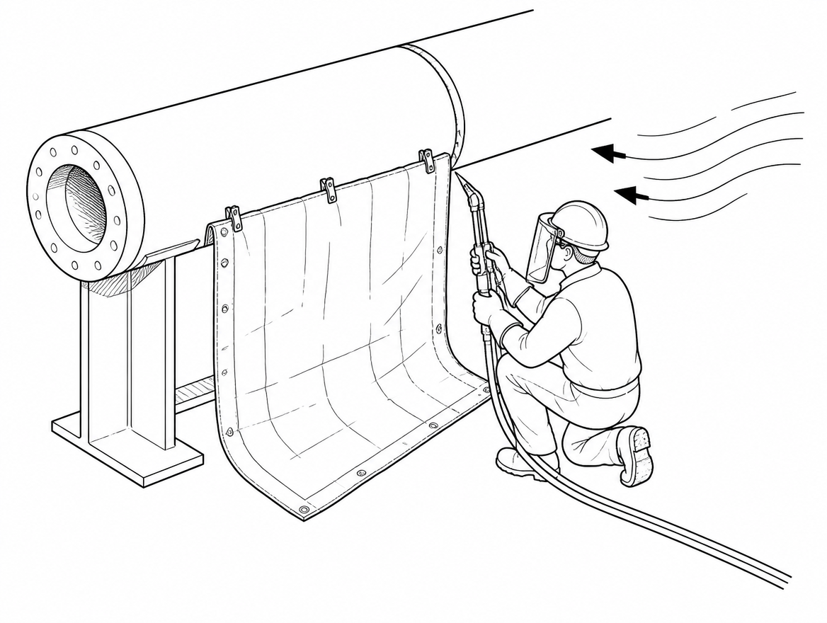
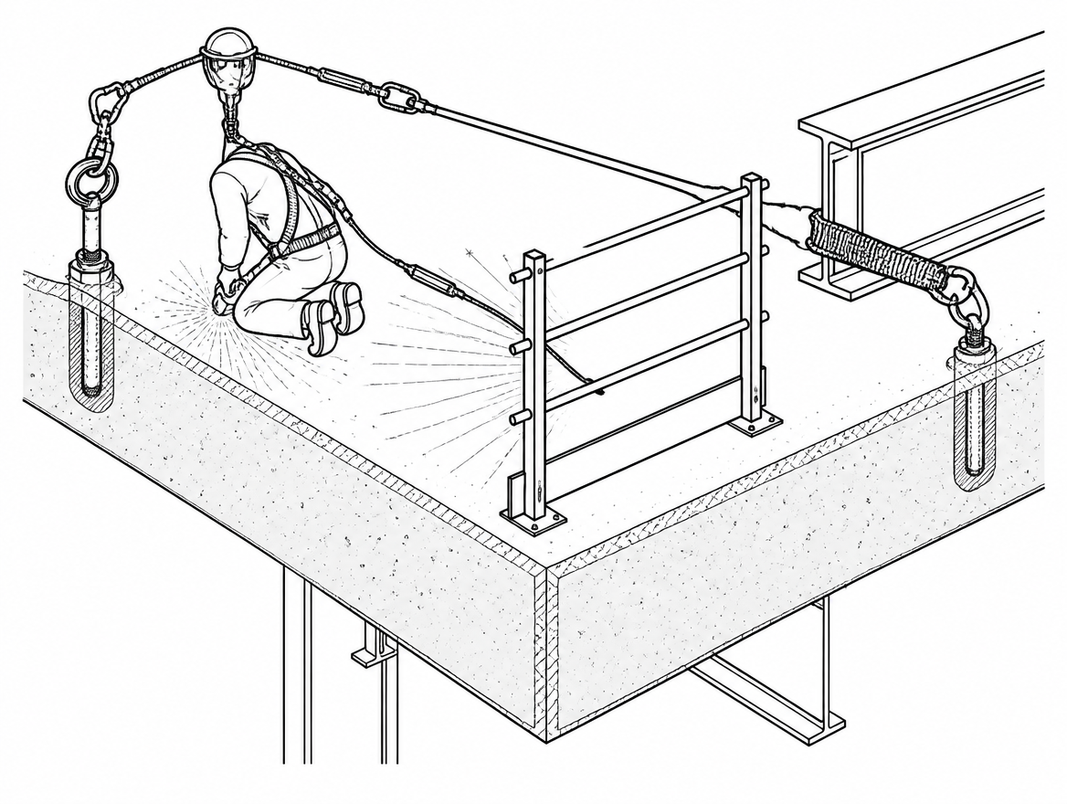
The controlling principle is positive separation: rig so that no credible spark, slag or spatter trajectory intersects any load-bearing textile.
- Work below and to the side of the anchor lines, not underneath them. Where the geometry forces the rope past the work zone, use a deviation to move it clear.
- Shield the trajectory. Welding blankets, spark-arresting sheets and transparent welding screens and curtains conforming to EN ISO 25980 contain the spread and also protect other trades from arc radiation. Blankets under a cutting position catch falling slag before it reaches ropes, hoses and combustibles below.
- Use heat-tolerant protection where contact cannot be avoided. Aramid, glass-fibre fabric or leather protectors, or a short steel wire rope strop as the connection nearest the hot work, instead of textile.
- Do not run textile lines alongside welding leads, gas hoses or hot workpieces. Route them on separate paths and secure both.
- Keep the working line and the backup line physically apart, on separate anchors and separate paths, so one spatter event or one edge cannot compromise both. Where a guided type fall arrester to EN 353-2 or a rope adjustment device to EN 12841 (Type A backup, Type B ascender, Type C descender) is in use, keep the device and its lanyard out of the spatter zone as well; connectors and cams are also damaged by adhering spatter.
PPE where cut and heat hazards coexist
Neither hazard is controlled by PPE alone, but the wrong PPE selection is a common gap on combined jobs, because a glove or garment chosen for one hazard is often poor against the other.
- Hands: mechanical risks to EN 388:2016+A1:2018 — note that cut resistance is now expressed with the TDM (ISO 13997) levels A to F, and that the older coup-test digit is not a substitute — combined with thermal risks to EN 407 where contact heat, radiant heat or molten metal splash is present. Handling freshly cut plate and handling ropes call for different gloves, and a cut-resistant glove with a fusible coating is a poor choice near spatter.
- Body: welding and allied processes clothing to EN ISO 11611, Class 1 or Class 2 selected according to the process and the spatter load; heat and flame protective clothing to EN ISO 11612 for other radiant and convective heat exposures. Garments must cover the harness where practicable so that spatter cannot lodge on webbing.
- Eyes and face: welding face protection to EN 175 with filters to EN 169, or automatic welding filters to EN 379; separate impact eye protection for grinding.
- Fall protection PPE: full body harnesses to EN 361, work positioning belts to EN 358 and sit harnesses to EN 813 are textile items in the spatter zone. Inspect webbing, stitching and adjuster paths for fused spots after every hot work shift.
- In potentially flammable atmospheres, verify the whole clothing system, including electrostatic dissipative requirements to EN 1149-5, before hot work is authorised.
Inspection, quarantine and retirement
EN 365 sets the framework for the instructions for use, records, periodic examination and marking of fall protection PPE, including periodic examination by a competent person at intervals of no more than 12 months, more frequently where use conditions justify it. Edges and hot work are exactly such conditions.
- Pre-use check and post-shift check. On jobs with edge contact or hot work, inspect at the end of the shift as well as the start. Damage is easier to trace to a cause while the setup is still rigged.
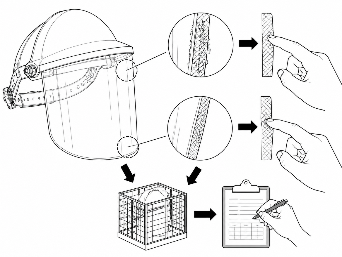
- Inspect by touch as well as by eye. Run the full length of rope hand-over-hand with bare or thin-gloved hands. Fused spatter damage feels hard, stiff and glassy; edge damage feels flat, thin or spongy where core fibres have broken.
- Quarantine immediately. Any glazed or melted area, exposed core, flat or soft section, or shifted sheath means the rope is withdrawn and tagged so it cannot be returned to service by mistake. The decision to retire belongs to the competent person, on the manufacturer’s criteria — not to the person who wants the job finished.
- Record it. Log the event in the equipment record: where the damage was, what caused it, what the rigging was. That record is what changes next week’s method statement.
Permit control and coordination between trades
Hot work near suspended access is a coordination problem before it is a technical one. The hot work permit should identify, by name and location, every rope, sling, lanyard, hose and cable within the spatter and slag trajectory, and state who verified their protection. It should also define the clearance zone for combustibles required by the site or insurer scheme, the fire-watch arrangement — commonly required to continue for a defined period after work stops, with a further check later in the shift — and the extinguishing provision, with extinguishers to EN 3-7 at the work position, not at ground level.
Where rope access technicians and welders are different contractors, the permit is the only place the two systems meet on paper. If the permit does not mention the ropes, nobody has checked them.
Takeaway
Treat the edge and the heat source as design inputs to the rigging plan, not as things to be managed afterwards with a sleeve and a hope. Rig the line clear of the edge first; if that is impossible, change the edge with rigid, structure-mounted protection; and only then cover the rope. Keep the working line and the backup line on separate paths and separate anchors so no single edge and no single spark shower can reach both. Then verify all of it against the manufacturer’s information and the equipment record required under EN 365 before the next shift starts on the same rig.
Next step: review the edge management section of the method statement for your current suspended access job against the anchor requirements in EN 795 and CEN/TS 16415, and confirm the hot work permit lists the ropes by location.
Frequently asked questions
Why can a rope that holds over 20 kN in a straight pull be cut by a hand load?
Because the static strength figure for low-stretch kernmantle rope to EN 1891 Type A is measured in a straight pull between terminations, and none of that figure survives contact with a small-radius edge. Over a burred corner the whole load is carried by the narrow band of sheath and outer core yarns crossing the edge radius, so lateral movement can sever the rope at a very low load.
What are the three mechanisms that make an edge destroy a loaded rope?
Stress concentration, where a radius smaller than the rope diameter loads only a narrow band of fibres; relative movement, where every ascent, descent, tool exchange or postural shift saws the rope across the corner, progressing from fuzzing to broken bearer strands to core exposure, sometimes within one work period; and dynamic loading, where a slip, swing or short fall arrest applies a peak force exactly where the rope is already deformed over the corner.
In what order should edge hazards be controlled?
Remove, protect, then cover. First re-rig so the rope never touches the edge — move the anchor back and higher, use a deviation, or install a re-anchor below the edge. Second, change the edge itself with edge rollers, rigid split-tube or channel protectors, edge plates or radiused edge blocks fixed to the structure. Third, and last, cover the rope with fabric protectors, sleeves or hose sections.
Why are fixed edge protectors better than fabric rope protectors?
Because they are attached to the building rather than the rope, edge rollers and rigid protectors give a large bearing radius and keep working while the rope moves under them, which is the normal condition during ascent and descent. Fabric protectors, sleeves and hose sections migrate with the rope unless independently restrained, and they hide the damage they are meant to prevent.
What placement rules keep sharp edge rope protection effective?
Tie the protector back to the structure with a separate cord or strap so rope movement cannot drag it off the edge; cover the whole travel zone rather than a single point, since the contact point migrates as the technician descends, the rope stretches and the worker swings; protect the working line and the backup line separately, because two ropes in one protector over one corner share one failure mode; confirm placement from the top before loading and on each pass; and check for grit, weld spatter, swarf or broken glass trapped under the protector, which acts as an abrasive.
Need this as a document you can issue? The template library gives you the risk assessments, permits and inspection logs in editable form — and employer plans cover a whole team with completion records.