Safety / Tips and Tricks / Rope access and confined space
Activity 01 · Rope access
Examples of Dangerous Connector Loading: How Carabiners and Snap Hooks Fail in Service
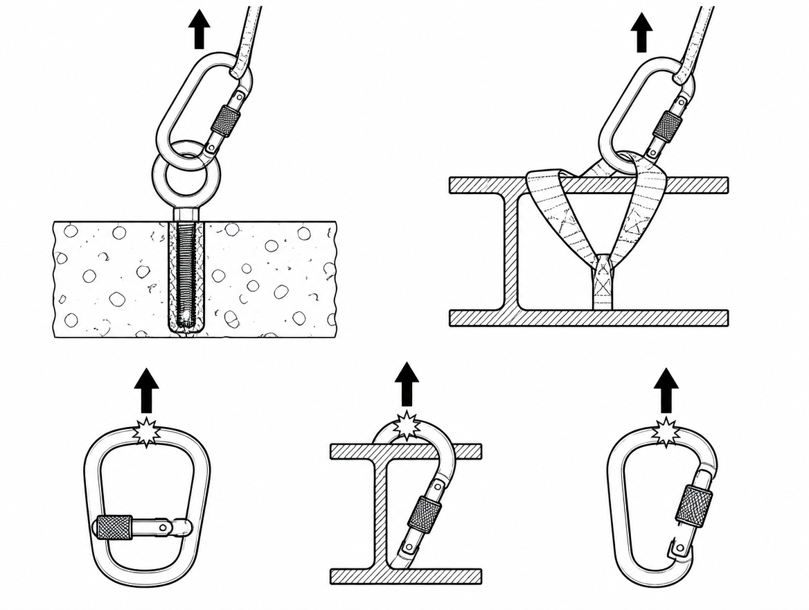
A connector rated at 15 kN on its major axis can fail at a small fraction of that figure if it is loaded across the gate, wedged over a beam flange, or left with the screw sleeve half-engaged. Nothing about the hardware changes between the safe case and the dangerous one — only its geometry under load. That makes connector loading hazards one of the few fall-protection problems that is almost entirely a matter of how the equipment is arranged at the point of attachment, which is to say: a matter for the person clipping in, and for the supervisor who signs off on the method.
This article works through the specific loading configurations that reduce connector strength or defeat the gate, what each one does mechanically, and how it is recognised during a pre-use check. The reference framework is EN 362 (connectors for personal fall protection), read alongside EN 361, EN 795 and EN 365.
What EN 362 actually certifies — and what it does not
EN 362:2004 covers connectors as an item of personal fall protection equipment and sets a minimum static strength of 15 kN, applied along the connector’s major axis with the gate closed and locked. It also requires that a connector be self-closing and either self-locking, or manually locking in a way that needs at least two consecutive, deliberate manual actions to open.
The standard divides connectors into classes, and the class determines what the connector was designed and tested to do:
- Class A — anchor connectors, designed to be attached to a specific type of structural element (for example a defined beam profile or eyebolt).
- Class B — basic connectors.
- Class M — multi-use connectors, designed and tested to be loaded on the major and minor axis.
- Class T — terminal connectors, intended to sit in a fixed orientation as part of a subsystem so that load is applied in a predetermined direction.
- Class Q — screw-link connectors, closed by a threaded sleeve or nut that must be fully tightened.
The important consequence: outside Class M, the 15 kN figure describes one axis and one gate state. EN 362 does not certify a minor-axis or gate-open strength for a standard Class B connector. Where a manufacturer publishes those figures voluntarily, they are typically well below the major-axis rating; where no figure is published, there is no basis for assuming any particular residual strength. Connectors marked to EN 12275 are climbing equipment certified against a different standard with different test criteria, and are not an automatic substitute for an EN 362 connector in a work system.
Connectors are Category III personal protective equipment under Regulation (EU) 2016/425, which is why the manufacturer’s instructions are not optional reading: the permitted loading directions and the compatible attachment-point geometry are specified there, not left to the user’s judgement.
Example 1: Minor-axis (cross) loading
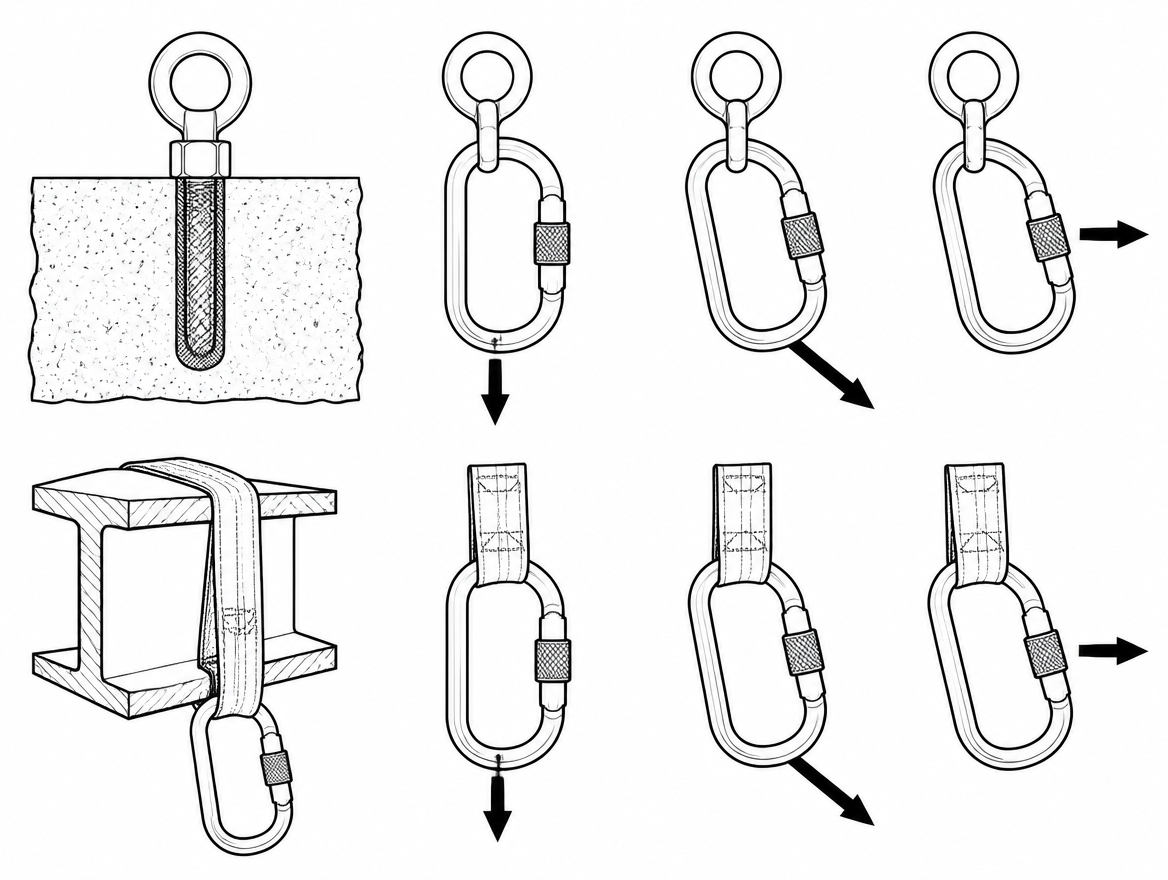
Cross-loading is the most common connector loading hazard on site, and the least visible. It occurs when the load line runs across the connector rather than along its spine — the load pushes outward on the gate and the back bar instead of pulling on the two ends of the frame.
Typical causes:
- A connector that has rotated inside a dorsal or sternal A attachment point on an EN 361 harness so that it lies flat against the webbing.
- A connector clipped into a wide webbing loop or bunched sling that grips the frame and holds it sideways.
- A connector trapped between the anchor and a structural face, unable to align itself when tension comes on.
In this orientation the gate becomes a load-bearing part of the frame, which it is not designed to be. A pin-and-notch or nose-hook closure resists a fraction of the axial rating before the nose deforms and the gate opens under load.
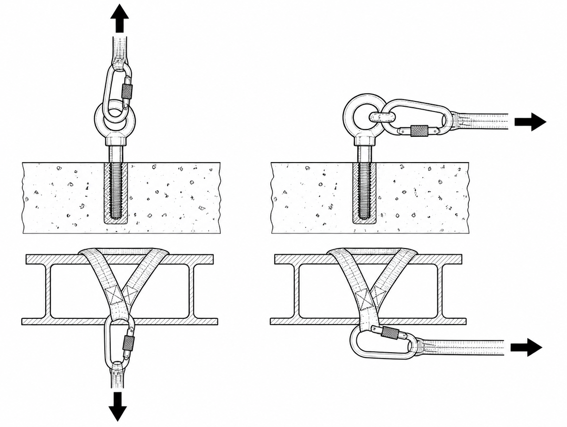
The controls are geometric, not procedural: use captive-eye or Class T terminal connectors where the connector must hold one orientation, use Class M connectors where minor-axis loading genuinely cannot be excluded, and select connectors whose frame is too large to be captured sideways by the attachment point it will be used with.
Example 2: Three-way loading
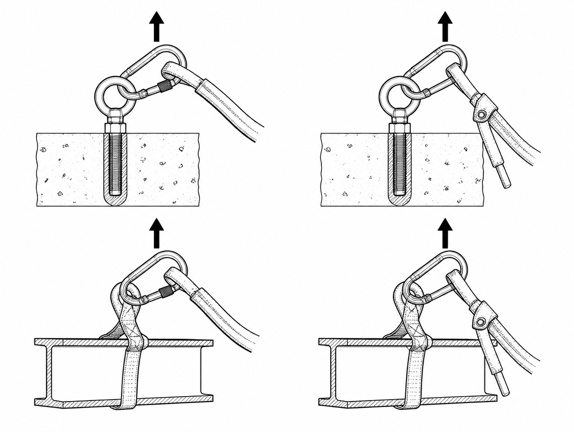
Three-way loading happens when a single connector carries loads pulling in three or more directions at once — for example an anchor sling, a lanyard leg and a rescue line all sharing one carabiner, or two slings arranged so that their combined force pushes the gate outwards.
The connector frame is designed as a two-point tension member. Introduce a third load path and part of the resultant force acts on the gate and on the mid-span of the back bar, producing bending rather than tension. The failure mode is gate deformation followed by the nose disengaging, often at loads that seem modest compared with the marked rating.
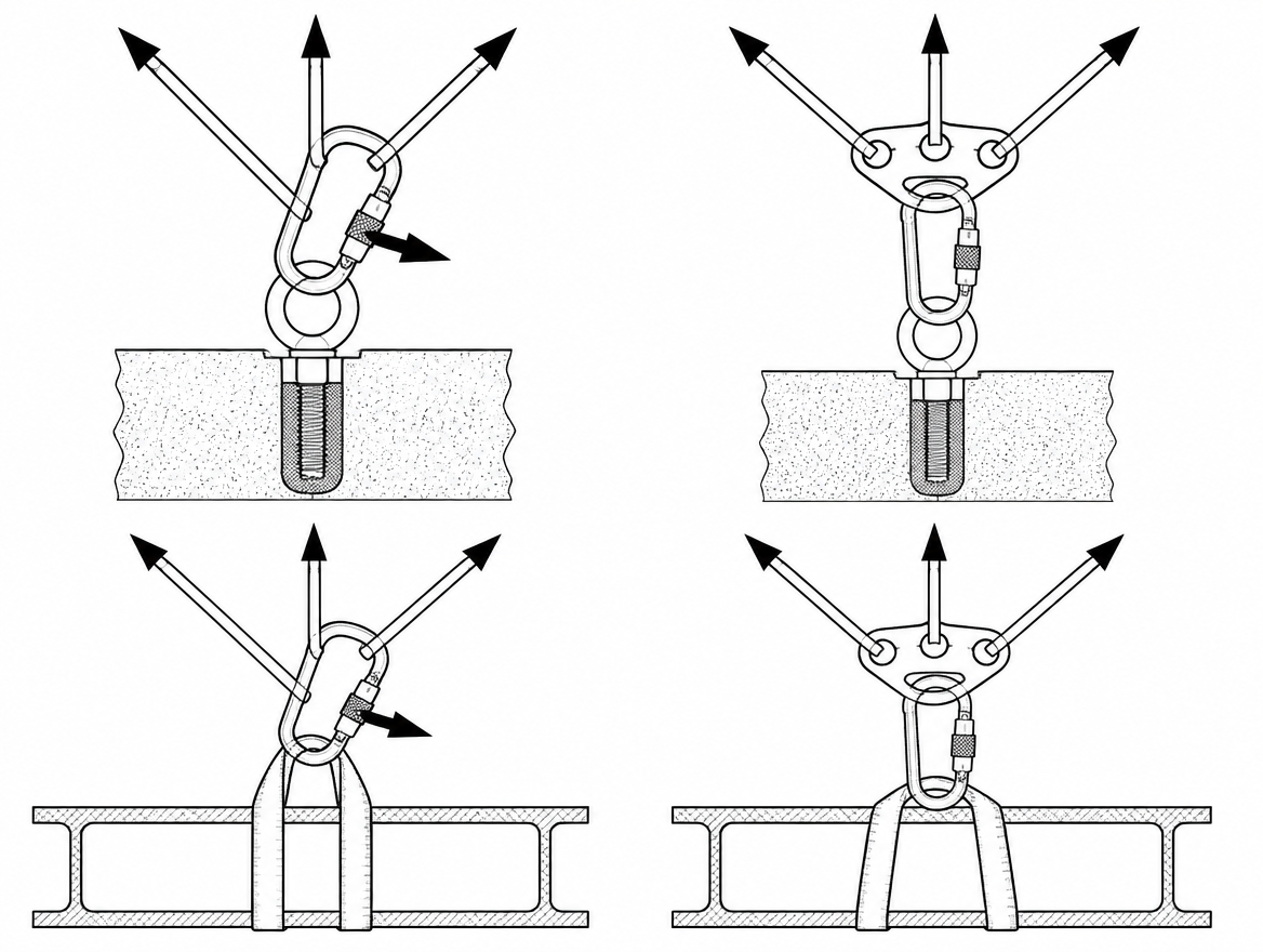
Where several components genuinely must meet, the correct fitting is a rated multi-point plate or ring designed for that purpose, or separate connectors on separate anchor points, sized so that each load path is independent.
Example 3: Gate-open and nose loading
A connector holds its rated strength only with the gate closed and locked. Two field conditions defeat this:
- Gate pressed open by the structure. The gate bears against a rung, bracket, edge or bolt head, and tension holds it open. The connector is then a hook.
- Nose loading. The connector hangs on the nose — the small tip beyond the gate — rather than on the back bar. The nose is a locating feature, not a load-bearing one.
Screw-gate sleeves add a specific failure path: vibration, repeated contact with the structure, or the gate rubbing against a surface can back the sleeve off over the course of a shift. Self-locking (twist-lock or triple-action) gates remove that particular hazard, which is why EN 362 permits a manually locking gate only where opening requires at least two consecutive deliberate actions.
Example 4: Roll-out on an incompatible attachment point
Roll-out is a compatibility failure, not a strength failure. A large-opening snap hook clipped to a small-diameter ring, a thin bracket, or another hook can rotate as the system takes tension. As it turns, the ring or bracket rides up onto the gate, depresses it, and the hook releases — with no component of the connector broken afterwards.
The mismatch to look for is between the depth of the hook throat and the size of the item it is clipped to. Any attachment point small enough to travel from the back bar to the gate can start the rotation, and any snap hook whose gate can be depressed from inside the throat can finish it.
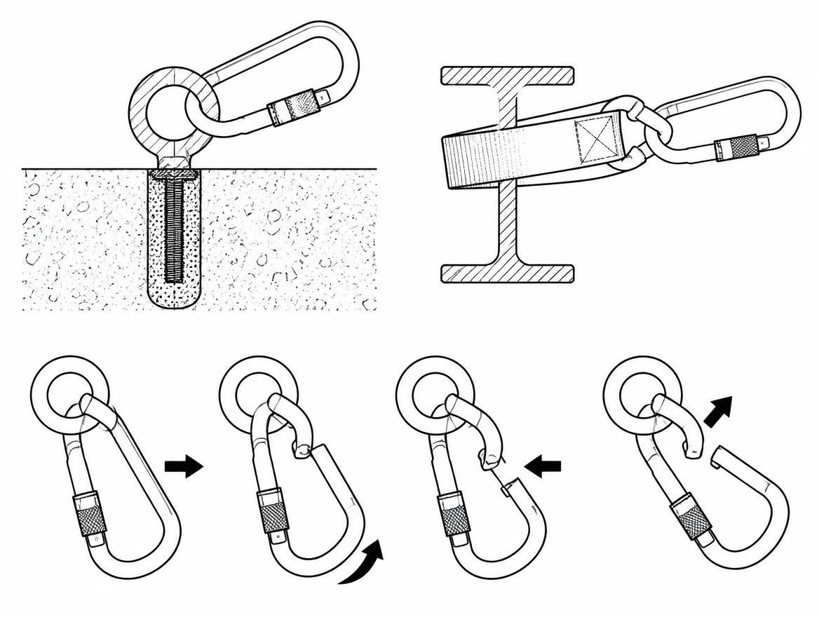
Compatibility is assessed against both manufacturers’ instructions — the connector’s and the anchor’s or harness’s. Where documentation does not confirm compatibility, the pairing is unproven, regardless of how well it appears to sit.
Example 5: Levering and prying over an edge or structural member
Wrapping a connector directly around a beam flange, an angle iron, a ladder stile or a scaffold tube puts the spine across a hard edge. Under load the connector is no longer in tension along its axis: it is being bent over a fulcrum, and the localised contact pressure at the edge is high enough to gouge aluminium frames.
The same mechanism appears when a connector is clipped through a hole that is too small — a pre-drilled plate or a lifting eye of insufficient bore — so the frame is pinched at two points and prevented from aligning with the load.
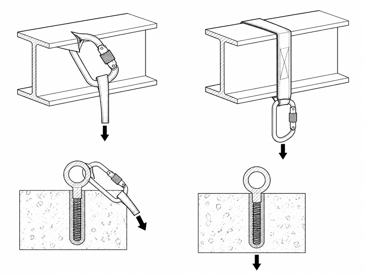
The correct arrangement is either a Class A anchor connector matched to that structural profile, or a rated anchor sling or strop taken around the member, with the connector attached to the sling’s eyes and free to hang in line with the load. Anchor devices themselves should be selected and installed to EN 795, with the anchor type (A to E) chosen for the structure and the intended direction of loading.
Example 6: Screw links closed only part-way
A Class Q screw link is rated only with the nut fully tightened so that the threads are completely engaged and the barrel covers the gap in the frame. Partially threaded, the link is a shape held together by a few threads, and it opens progressively under load.
Class Q links are also frequently the wrong tool for a connection that is made and broken every shift: they invite hand-tightening “just enough”, and they cannot be checked at a glance from three metres away the way a self-locking gate can. They belong in semi-permanent connections that are set up once, verified, and then left alone — not in daily-use lanyard attachments.
Example 7: Parking an unused lanyard leg on a load-bearing point
With a twin-leg (Y) lanyard, the unused leg has to go somewhere during transit. Two habits create loading problems:
- Clipping the unused leg back into the harness attachment point. The dorsal or sternal A point then holds two connectors, and in a fall the parked leg’s connector can be cross-loaded, pinched, or can transfer part of the arrest force through the energy absorber’s stitching in an unintended direction.
- Clipping the unused leg back onto the loaded leg or its energy absorber. This can restrain the absorber, interfere with its deployment, and load a connector against webbing rather than against a rated eye.
Harnesses and lanyards intended for twin-leg use provide a designated parking point or lanyard keeper that is deliberately made to release under load rather than to carry it. The manufacturer’s instructions state which point that is; if the harness in use has none, the assembly is not suited to twin-leg working at height.
Example 8: Connector-to-connector and choker attachments
Clipping one snap hook directly into another, or into a D-ring already occupied by a second hook, produces a joint with no defined loading axis: each connector can lever against the other’s gate as the system moves. The same applies to “choking” a lanyard around a structural member and clipping the hook back onto the lanyard’s own webbing — the connector is loaded against a soft, movable surface, the webbing is compressed against the structure, and the assembly is no longer the configuration that was tested.
Where a lanyard is designed for choker use, the manufacturer says so and specifies the minimum member size and the surface condition. Where it is not, an anchor sling or a Class A connector matched to the member is the correct component.
Example 9: Loading a connector that has already been shock-loaded or is worn
A connector that has arrested a fall, or that has taken any shock load of unknown magnitude, is withdrawn from service pending assessment. Overload can leave a frame slightly opened, a gate seating imperfectly, or a nose deformed by a few tenths of a millimetre — enough to allow the gate to slip past the nose under a load that the connector should have held easily.
The wear indicators to look for during a pre-use check are specific:
- Grooving or a flat spot where a rope, sling or wire has run over the frame — particularly on aluminium.
- A gate that does not spring fully shut and seat against the nose without help.
- A gate that can be pushed sideways out of the nose notch, or a visible gap when closed.
- A locking sleeve that binds, is gritty, or does not run to its full travel.
- Corrosion, especially pitting at the hinge and at the spring housing.
- Any bend, twist, sharp edge, or evidence of heat or chemical exposure.
EN 365 requires periodic examination of this equipment by a competent person at intervals of no more than 12 months, alongside the pre-use check by the user before every use. Manufacturers’ instructions and the site risk assessment can set a shorter interval, and frequently do for high-cycle or corrosive environments.
Designing loading errors out of the system
Every configuration above is avoidable at specification stage more reliably than at the point of use. Practical measures:
- Specify connector classes by task — Class A connectors for defined structural profiles, Class T where orientation must be fixed, Class M only where minor-axis loading is genuinely part of the design intent.
- Use captive-eye connectors and swivels on subsystems that rotate, so the connector cannot align itself across the attachment point.
- Standardise harness and anchor attachment-point sizes across a site so that hook-throat compatibility is a purchasing decision rather than a judgement made on a roof.
- Provide rated anchor slings on every kit that may need to attach to structural steel, so that wrapping a connector around a flange is never the only option available.
- Record compatibility decisions as part of the fall-protection system documentation — within an ISO 45001 management system, this is operational control, and connector pairings belong in it in the same way rescue arrangements do.
Takeaway for the pre-use check
Three questions cover the majority of connector loading hazards, and all three can be asked in the few seconds before tension comes on the system:
- Can this connector hang in line with the load? If it is pinched, wedged, or held sideways by webbing or structure, the marked rating no longer applies.
- Is the gate closed, locked, and clear of the structure? Nothing should be bearing on the gate, and the sleeve should be at full travel.
- Can the attachment point travel to the gate? If it is small enough to move from the back bar onto the gate, roll-out is possible and the pairing needs re-checking against both sets of instructions.
For the next step, read the connector’s instructions for use against the anchor and harness attachment points actually in service, and record any pairing that the documentation does not explicitly support — that list is the input to both the periodic examination under EN 365 and the next round of equipment procurement.
Frequently asked questions
What does the 15 kN rating on an EN 362 connector actually cover?
EN 362:2004 sets a minimum static strength of 15 kN applied along the connector's major axis with the gate closed and locked. Outside Class M, that figure describes one axis and one gate state only — the standard does not certify a minor-axis or gate-open strength for a standard Class B connector.
What are the EN 362 connector classes?
Class A are anchor connectors designed for a specific type of structural element, such as a defined beam profile or eyebolt. Class B are basic connectors. Class M are multi-use connectors designed and tested for loading on both the major and minor axis. Class T are terminal connectors intended to sit in a fixed orientation within a subsystem. Class Q are screw-link connectors closed by a threaded sleeve or nut that must be fully tightened.
What causes cross-loading (minor-axis loading) on site?
Cross-loading occurs when the load line runs across the connector rather than along its spine. Typical causes are a connector that has rotated inside a dorsal or sternal A attachment point so it lies flat against the webbing, a connector clipped into a wide webbing loop or bunched sling that grips the frame sideways, and a connector trapped between the anchor and a structural face so it cannot align when tension comes on. In this orientation the gate becomes a load-bearing part of the frame, which it is not designed to be.
Why is three-way loading dangerous?
The connector frame is designed as a two-point tension member. When a single connector carries loads pulling in three or more directions — for example an anchor sling, a lanyard leg and a rescue line sharing one carabiner — part of the resultant force acts on the gate and the mid-span of the back bar, producing bending rather than tension. The failure mode is gate deformation followed by the nose disengaging, often at loads that seem modest compared with the marked rating. Where several components must meet, use a rated multi-point plate or ring, or separate connectors on separate anchor points.
Can a climbing carabiner marked EN 12275 be used instead of an EN 362 connector?
No, not automatically. Connectors marked to EN 12275 are climbing equipment certified against a different standard with different test criteria, and are not an automatic substitute for an EN 362 connector in a work system. Connectors are Category III personal protective equipment under Regulation (EU) 2016/425, and the manufacturer's instructions specify the permitted loading directions and compatible attachment-point geometry.
Need this as a document you can issue? The template library gives you the risk assessments, permits and inspection logs in editable form — and employer plans cover a whole team with completion records.