Safety / Tips and Tricks / Rope access and confined space
Activity 01 · Rope access
Tyrolean Tensioning: Managing Sag, Line Tension and Anchor Loads
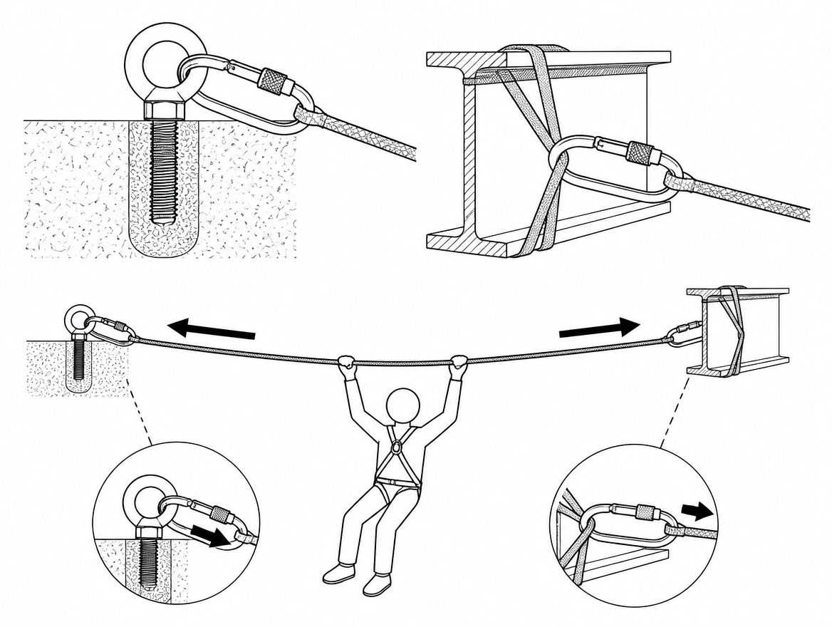
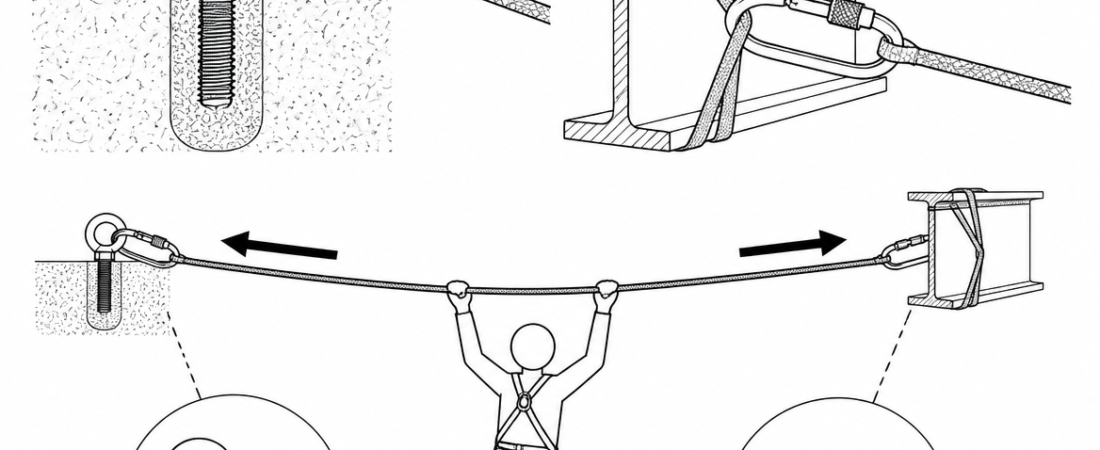
When a Tyrolean traverse fails, the cause is rarely a rope that was too weak for the person hanging on it. It is far more often a line that was pulled too tight. Tension in a near-horizontal rope is governed by geometry, not by the weight of the load: as the sag reduces, the force in the line and at both anchors rises steeply, and it does so without any visible warning to the team on the haul rope. A single rigger with a 4:1 system can put more force into a traverse line than the load will ever apply. Tyrolean tensioning is therefore a load-control task first and a rigging task second, and the target tension belongs on the rigging plan before anyone touches a pulley.
The geometry that sets every other decision
For a point load at mid-span, the tension in each leg of the line is approximately:
T = W / (2 sin θ), where θ is the angle of the loaded rope measured from the horizontal, and W is the load.
Expressed as sag over span (d/L), the small-angle approximation is T ≈ W × L / (4d). The consequence is worth reading as numbers rather than as a principle:
| Sag as % of span (d/L) | Rope angle from horizontal | Tension multiplier | Line tension with a 1 kN load (one person plus kit) | Line tension with a 2 kN load (rescue load) |
|---|---|---|---|---|
| 20% | 21.8° | ×1.35 | 1.35 kN | 2.7 kN |
| 10% | 11.3° | ×2.5 | 2.5 kN | 5.1 kN |
| 5% | 5.7° | ×5.0 | 5.0 kN | 10.1 kN |
| 2% | 2.3° | ×12.5 | 12.5 kN | 25 kN |
These figures assume the load sits at mid-span (the worst case for sag) and ignore the weight of the rope itself and any pre-tension already in the system, both of which add to the total. The practical reading is that a visually flat traverse carrying a rescue load can approach or exceed the knotted minimum static strength of the rope that forms it, while the same load on a line with 10% sag sits at a small fraction of it.
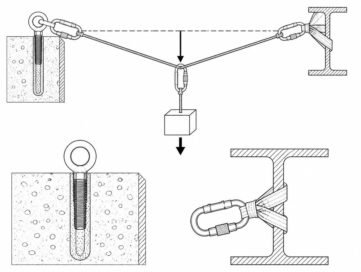
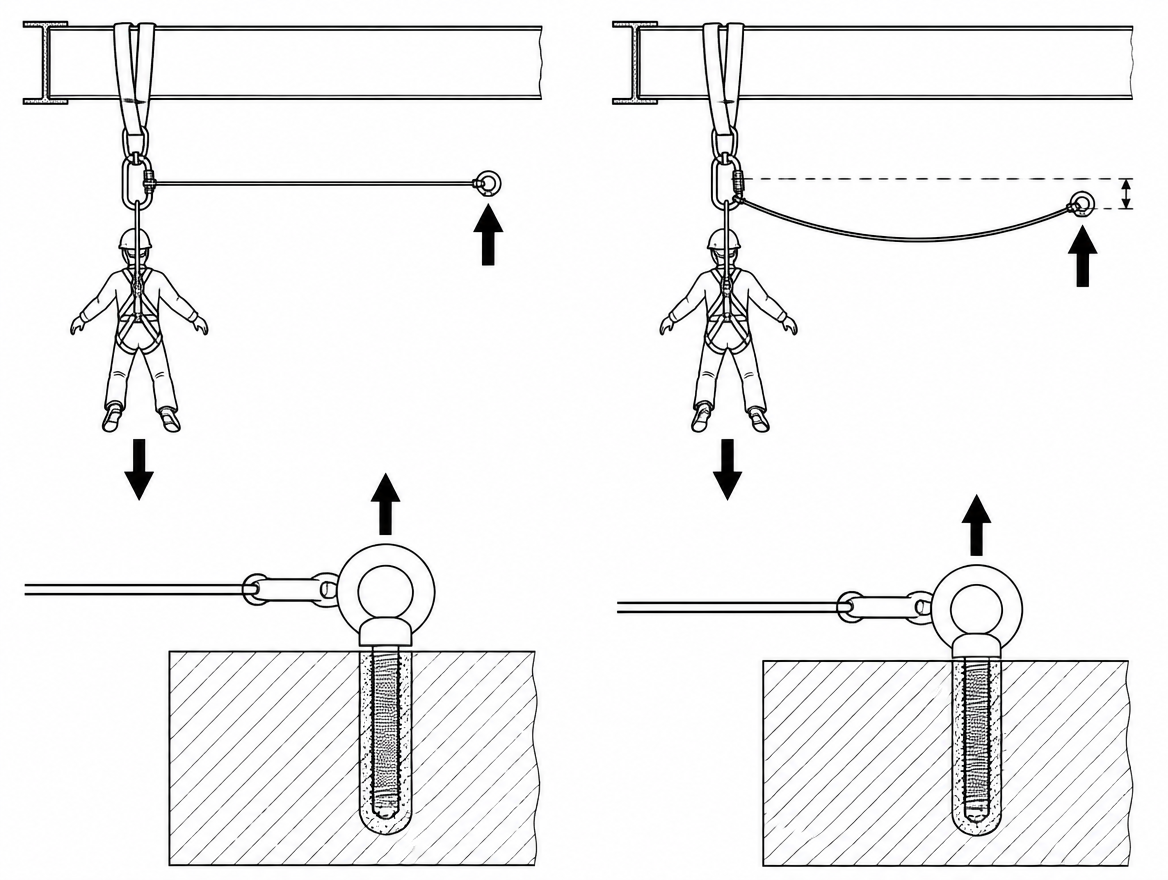
Sag is not a compromise or an aesthetic failure. It is the mechanism that keeps line tension and anchor load inside the values the system was designed for. The design question is not how to remove sag but how much sag the site can accommodate while keeping the loaded load clear of the ground, the structure and any obstruction below.
Rope selection and terminations for a tensioned line
The traverse line is normally low-stretch kernmantel rope to EN 1891, Type A, typically 10.5–11 mm in industrial use. EN 1891 sets a minimum static strength of 22 kN for Type A rope without terminations and 15 kN with figure-of-eight terminations at both ends; Type B values are 18 kN and 12 kN respectively. Elongation is limited to 5% between loads of 50 kg and 150 kg, which matters on a traverse for two reasons: the line will sag further under load than it does when tensioned empty, and a long span stores a meaningful amount of energy once tension is high.
Two points follow directly from those numbers:
- The strength figure to design against is the knotted figure, not the unknotted one, because a Tyrolean is terminated at both ends.
- Where a termination can be made without a knot – a tensionless hitch or rope wrap around a suitable structural section of adequate diameter, or a sewn termination supplied and rated by the manufacturer – more of the rope strength is retained. A tensionless wrap also spreads the load over a length of the structure rather than concentrating it in one bend.
Dynamic mountaineering rope to EN 892 is not appropriate as a traverse line: its elongation makes sag control impractical and the loaded sag unpredictable.
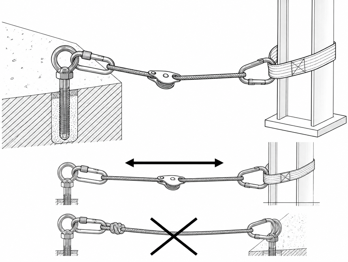
Anchors are loaded horizontally, and most anchor products are not tested that way
A tensioned traverse loads its anchors along the line of the rope – predominantly horizontally, and continuously for as long as the line is rigged. That is a different load case from the one most anchor devices are qualified for.
- EN 795:2012 classifies anchor devices as Type A (structural anchors), Type B (transportable), Type C (flexible horizontal anchor lines), Type D (rigid rails) and Type E (deadweight). The standard covers devices for use by one person; CEN/TS 16415 is the technical specification that addresses anchor devices used by more than one person at the same time – directly relevant to a traverse that will carry a rescuer and a casualty.
- A Type B or Type E device is tested in defined directions of loading. A device qualified for a vertical fall-arrest pull is not automatically suitable for sustained multi-kilonewton horizontal tension. The manufacturer instructions supplied under Regulation (EU) 2016/425 state the permitted directions of use, and they are the governing document.
- A site-rigged Tyrolean built from rope, slings to EN 566 and connectors to EN 362 is not itself a CE-marked anchor device. The anchor points it uses, and the structure behind them, need assessment by a competent person against the actual calculated line tension – not against a generic assumption.
Where the load is shared between two anchor points, the included angle between the legs controls how much each leg carries. At 90° each leg takes about 71% of the resultant; at 120° each leg takes 100% of it. Keeping shared-anchor angles well below 90° keeps the arithmetic in the team’s favour.
Building the tensioning system
A workable Tyrolean tensioning system does three things: it applies force in a controlled amount, it holds that force without relying on someone’s grip, and it can be released under load in a controlled way. A typical arrangement at the tension end:
- Fix and back up the far end first. Terminate the traverse line at the far anchor – tensionless wrap or a figure-of-eight on a bight into connectors to EN 362 – and rig the independent back-up before any tension is applied.
- Rig the haul at the near anchor. A 3:1 (Z-rig) built with pulleys certified to EN 12278 is enough for most spans. Real efficiency is well below the theoretical ratio once sheave friction and rope bends are counted, but the ceiling on force is the point: a low-ratio system limits how badly the line can be over-tensioned.
- Use a rope clamp rated for the job. Rope adjustment devices to EN 12841 are classified as Type A (safety line back-up), Type B (ascent) and Type C (descent). A Type B ascender is designed for a person’s body weight on a working line; toothed cams can damage or sever a sheath at haul-system forces. Where the calculated tension approaches the device’s stated limits, a purpose-made rigging grab or a device the manufacturer specifically permits for hauling is required.
- Capture progress and hold the tension mechanically. A progress-capture device or a friction-hitch back-up holds the line between hauls so that no part of the tension depends on someone maintaining a pull.
- Put a load cell in line. An inline dynamometer between the anchor and the traverse line is the only way to know what the tension actually is. Without one, the team is estimating a value that changes by a factor of five across a few degrees of angle.
- Do not tension with a vehicle, capstan winch or lever hoist unless tension is measured and limited. These devices can generate far more force than the rope, the anchors or the structure will accept, and they give no useful feedback through the operator’s hands.
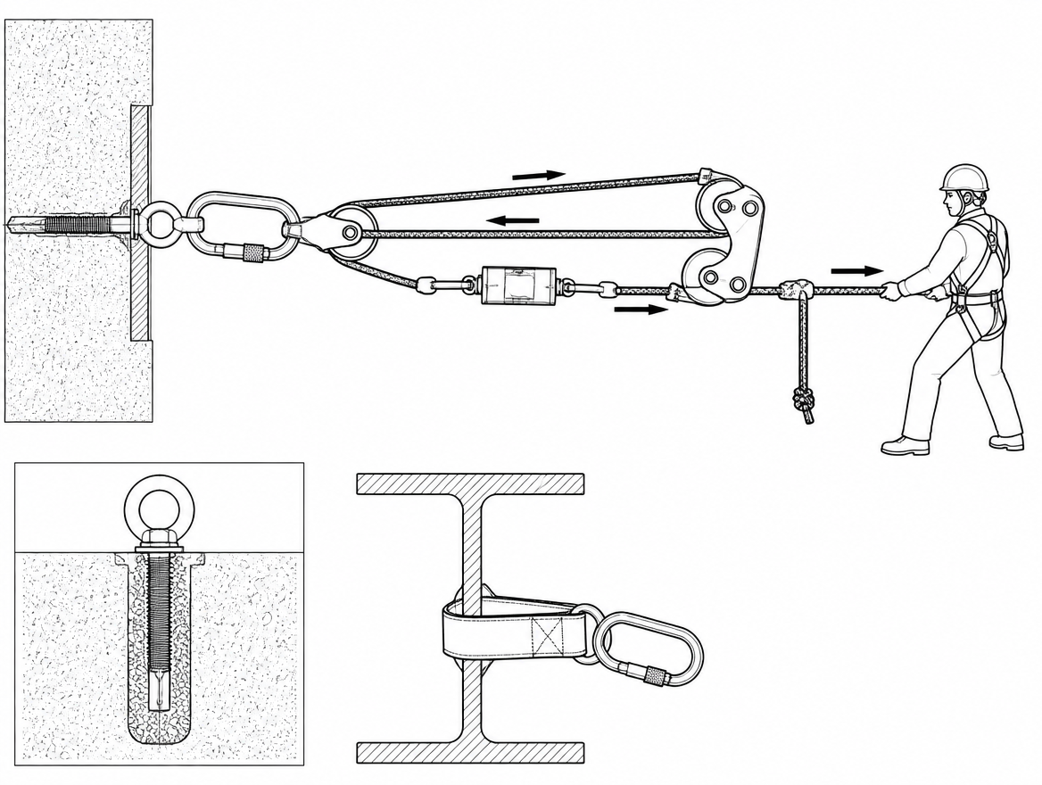
Redirects deserve their own check. Where the line or the haul rope turns 180° around a pulley, the resultant force on that pulley and its anchor is approximately twice the line tension. A redirect that looks incidental can be the most heavily loaded component in the system.
Deciding how much tension, and confirming it
The tension target is set on the ground, from the span, the maximum intended load and the clearance available beneath the line. A defensible sequence:
- Establish the maximum load the traverse will carry, including a rescue load with two people and equipment if that is a foreseeable use.
- Establish the minimum clearance required below the loaded line at mid-span, allowing for rope elongation under load.
- Work out the maximum permissible sag from that clearance, then calculate the resulting line tension from the geometry above.
- Compare that tension against the knotted strength of the rope, the rating of every component in the line, the anchor device ratings and the competent person’s assessment of the structure – using the design factor set out in the organisation’s own procedures, stated as a number in the rigging plan rather than left to judgement on site.
- Tension to the target reading on the load cell, then verify the unloaded sag against a fixed reference point so the setting can be reproduced and checked later.
If the clearance available cannot be achieved at an acceptable tension, the answer is a different rigging solution – a shorter span, a raised anchor, an intermediate support, or a different access method – not more tension.
Two ropes, and how the load is attached
Directive 2009/104/EC on the use of work equipment requires, for rope access and positioning techniques, a separately anchored working line and safety line, with the worker connected to both. On a traverse this is usually met either by a twin-rope traverse with a twin-sheave trolley and two independent connections, or by a single track line plus a separately anchored belay or safety line running to the load.
Practical points for the load end:
- Full body harness to EN 361 for fall arrest attachment, in combination with a sit harness to EN 813 or a work positioning belt to EN 358 where the task requires suspension or positioning.
- Connectors to EN 362, locking, and loaded along the major axis. Trolley and connector geometry should prevent cross-loading or gate contact as the load traverses.
- Tag lines at both ends so the load can be controlled and recovered without anyone hauling on the tensioned line itself.
- Edge protection wherever the tensioned rope contacts structure. A line under several kilonewtons of tension abrades quickly, and abrasion at an edge is the most common damage mechanism on a traverse.
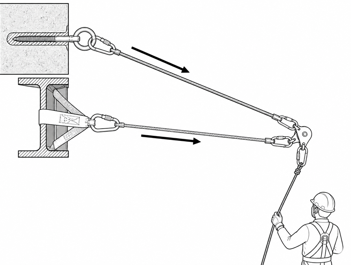
Planning the release before applying the tension
A traverse that cannot be de-tensioned under load is a trap. If the plan includes lowering the load to the ground at mid-span, or slackening the line to bring a casualty over an obstacle, the tension end must be rigged through a device that can be released and controlled under load – a descender or lowering device suited to the calculated force, per its manufacturer instructions – rather than terminated in a knot that has to be cut or a grab that has to be forced.
The same applies at the end of the shift: controlled release of stored energy, with the team clear of the line and of the haul system, and no one standing in the plane of the rope while tension is coming off.
Inspection and records
- Pre-use check of the rope over its full length, terminations, pulleys, clamps, connectors and anchor interfaces, by the user, before each rigging.
- Periodic examination by a competent person at intervals not exceeding 12 months, in line with EN 365, and more frequently where the manufacturer instructions or the severity of use require it. Rope used repeatedly under high tension at edges warrants a shorter interval.
- Post-event examination and quarantine of any component that has been loaded beyond its intended service conditions, including a line found to have been tensioned above the planned value.
- Documented rigging plan recording span, maximum intended load, target tension, measured tension, sag and anchor assessment. For organisations running a management system to ISO 45001, this is the record that demonstrates the control was actually applied rather than assumed.
Failure patterns that keep recurring
- Tensioning by feel, with no load cell, until the line looks straight.
- High-ratio haul systems (6:1, 9:1) used on the traverse line because the low-ratio system felt like hard work.
- A toothed personal ascender used as the haul grab and left in the tensioned line.
- Anchor devices qualified for vertical loading used to hold sustained horizontal tension.
- No independent back-up at one or both ends, or a back-up that shares the same anchor point as the primary.
- Clearance checked against the unloaded sag, so the loaded line brings the person into contact with the ground or an obstruction.
- No means of releasing tension under load, discovered only when a load has to be lowered at mid-span.
The takeaway to carry to the next rig
Tension is a calculated value, not a feel. Before the next traverse is rigged, the rigging plan should state four numbers: the span, the maximum intended load, the maximum permissible sag derived from the clearance below, and the resulting line tension in kilonewtons – with an inline load cell on site to confirm it. Where those numbers cannot be reconciled with the knotted strength of the rope to EN 1891, the ratings of the anchor devices under EN 795 and CEN/TS 16415, and the competent person’s assessment of the structure, the span or the method changes.
For the next step, work through the anchor side of the problem: an anchor selection and assessment review against the horizontal load case, using the manufacturer instructions for every device in the line and the multi-user provisions of CEN/TS 16415 where more than one person may be on the traverse at once.
Frequently asked questions
How is tension in a Tyrolean line calculated?
For a point load at mid-span, the tension in each leg is approximately T = W / (2 sin θ), where θ is the angle of the loaded rope measured from the horizontal and W is the load. Expressed as sag over span (d/L), the small-angle approximation is T ≈ W × L / (4d).
How much does sag change the line tension?
At 20% sag (21.8°) the multiplier is about ×1.35, at 10% sag (11.3°) it is ×2.5, at 5% sag (5.7°) it is ×5.0 and at 2% sag (2.3°) it is ×12.5. So a 1 kN load gives about 1.35 kN, 2.5 kN, 5.0 kN and 12.5 kN respectively, while a 2 kN rescue load at 2% sag reaches about 25 kN. These figures assume the load sits at mid-span and ignore rope weight and any pre-tension, both of which add to the total.
What rope should be used for a traverse line?
The traverse line is normally low-stretch kernmantel rope to EN 1891, Type A, typically 10.5–11 mm in industrial use. EN 1891 requires a minimum static strength of 22 kN for Type A without terminations and 15 kN with figure-of-eight terminations at both ends; Type B values are 18 kN and 12 kN. Elongation is limited to 5% between loads of 50 kg and 150 kg. Dynamic mountaineering rope to EN 892 is not appropriate, because its elongation makes sag control impractical and the loaded sag unpredictable.
Why is a knot-free termination preferred?
Because a Tyrolean is terminated at both ends, the strength figure to design against is the knotted figure, not the unknotted one. Where a termination can be made without a knot – a tensionless hitch or rope wrap around a suitable structural section of adequate diameter, or a manufacturer-rated sewn termination – more of the rope strength is retained. A tensionless wrap also spreads the load over a length of the structure rather than concentrating it in one bend.
Why are anchor ratings a particular concern on a Tyrolean?
A tensioned traverse loads its anchors along the line of the rope – predominantly horizontally, and continuously for as long as the line is rigged – which differs from the load case most anchor devices are qualified for. EN 795:2012 classifies devices as Types A to E and covers use by one person, while CEN/TS 16415 addresses devices used by more than one person at a time, directly relevant where a rescuer and casualty are carried. A device qualified for a vertical fall-arrest pull is not automatically suitable for sustained multi-kilonewton horizontal tension, and the manufacturer instructions supplied under Regulation (EU) 2016/425 are the governing document. Where load is shared between two anchor points, each leg takes about 71% of the resultant at 90° and 100% at 120°.
Need this as a document you can issue? The template library gives you the risk assessments, permits and inspection logs in editable form — and employer plans cover a whole team with completion records.