Safety / Tips and Tricks / Rope access and confined space
Activity 01 · Rope access
Tyrolean Traverse Technique: Tension, Anchors and Backup on a Horizontal Rope
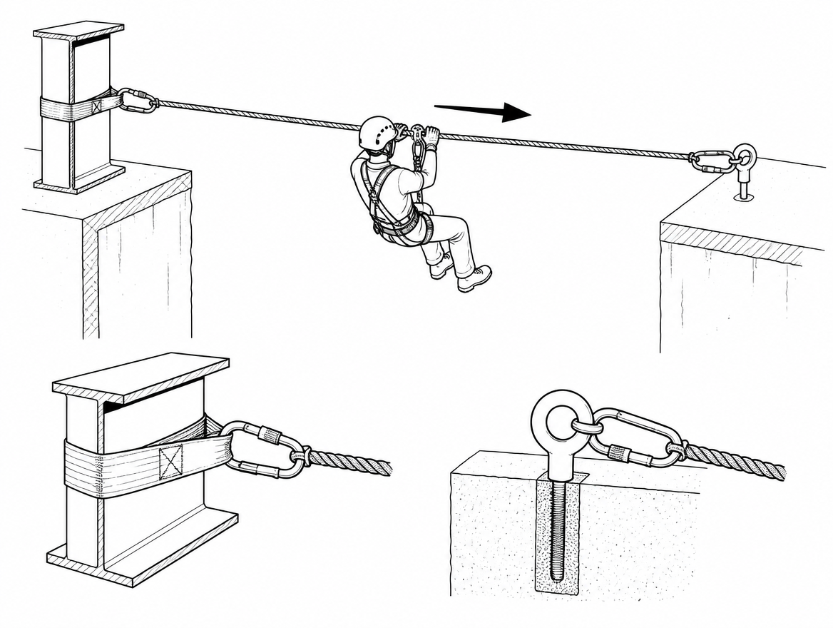
A Tyrolean traverse moves a person or a load along a tensioned rope between two anchor points, usually across a gap that cannot be crossed on foot: a shaft, a river, a gap between two structures, a spill basin, a section of collapsed access. The technique is well known from mountaineering and technical rescue, and it appears in industrial work far more often than most safety files acknowledge. The critical point for anyone planning one is that a Tyrolean traverse is not a footbridge with rope instead of steel. It is a highly tensioned system in which anchor loads can be several times the weight being carried, and the two failure paths that matter most – anchor failure and rope damage at an edge – both stem from decisions taken before anyone leaves the ground.
This article covers the geometry that drives anchor loading, the EN standards that apply to the components, the two-rope principle that European work-at-height law requires for rope access, and the rescue provision that has to exist before the first traverse is made.
Where a Tyrolean traverse belongs in a work-at-height plan
Under the work equipment provisions for temporary work at height in Directive 2009/104/EC (Annex II, section 4), rope access and positioning techniques sit low in the hierarchy: they are used where the risk assessment shows that other means of access are not reasonably practicable, and only where the system comprises at least two separately anchored lines – one working line and one safety line – with the worker connected to both. A Tyrolean traverse is a specific application of that principle turned through 90 degrees. The requirement does not relax because the rope is horizontal.
EN ISO 22846-1 (fundamental principles) and EN ISO 22846-2 (code of practice) set out the framework for rope access work, including planning, competence, supervision and equipment management. Where a traverse is used to move materials rather than people, the same anchor and rope engineering applies, but the acceptance criteria for the load path and the consequences of a drop must be assessed separately.
Sag is not sloppiness – it is the load control
The single most misunderstood aspect of the tyrolean traverse technique is tension. Intuition says a tight rope is a safe rope. The mechanics say the opposite: the flatter the rope, the higher the tension needed to support the same weight, and the higher the load transmitted into both end anchors.
For a load hanging at mid-span on a straight rope, the tension in each leg is approximately W / (2 sin θ), where θ is the angle of each rope leg below horizontal. The resulting multipliers are steep:
| Sag at mid-span (% of span) | Approx. angle of each leg | Approx. tension per leg (× suspended load) |
|---|---|---|
| 2% | ~2.3° | ~12.5× |
| 5% | ~5.7° | ~5.0× |
| 10% | ~11.3° | ~2.5× |
| 15% | ~16.7° | ~1.7× |
| 20% | ~21.8° | ~1.35× |
These figures are an idealised static case: a point load at mid-span, rope weight ignored, no friction and no dynamic movement. Real systems add the pre-tension already in the rope before anyone loads it, plus any bounce, swing or arrested momentum. That is why a working target of no less than 10% sag at mid-span under load is common practice in rescue and rope access teams, and why systems built with a mechanical advantage haul left cranked tight are the ones that break end anchors.
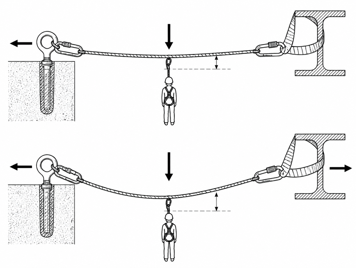
Two practical consequences follow. First, tension should be measured, not estimated: an inline load cell or dynamometer between the tensioning system and the anchor turns a guess into a number that can be recorded. Second, the tensioning system must be releasable under load, so the traverse can be lowered rather than cut if a person or load has to be brought down mid-span.
End anchors: two independent points at each end
Both ends of a traverse carry the full rope tension, not half of it. Anchor provision therefore has to be sized against the measured or calculated tension, with a margin, and not against body weight.
- Structural anchors conforming to EN 795 Type A, or verified structural steelwork assessed by a competent person, are the usual basis. Type B (transportable) and Type E (deadweight) devices are rarely appropriate for the horizontal, sustained, high-magnitude loading of a traverse unless the manufacturer explicitly permits it.
- Scope limits matter. An EN 795 Type C horizontal lifeline is a fall-arrest anchor line for a person clipped beneath it. It is not tested or certified as a track line for traversing on a trolley, and using one that way falls outside the manufacturer’s instructions.
- Multi-person use is not covered by EN 795 alone. CEN/TS 16415 sets out the test requirements for anchor devices used by more than one person simultaneously – relevant as soon as a rescuer joins a casualty on the same system.
- Redundancy at each end means two independent anchor points, equalised or load-distributed, with sling angles kept narrow. Slings to EN 566 and connectors to EN 362 with locking gates complete the chain; the internal angle between legs of a load-sharing sling should be kept well under 90°, because tension in each leg rises sharply beyond that.
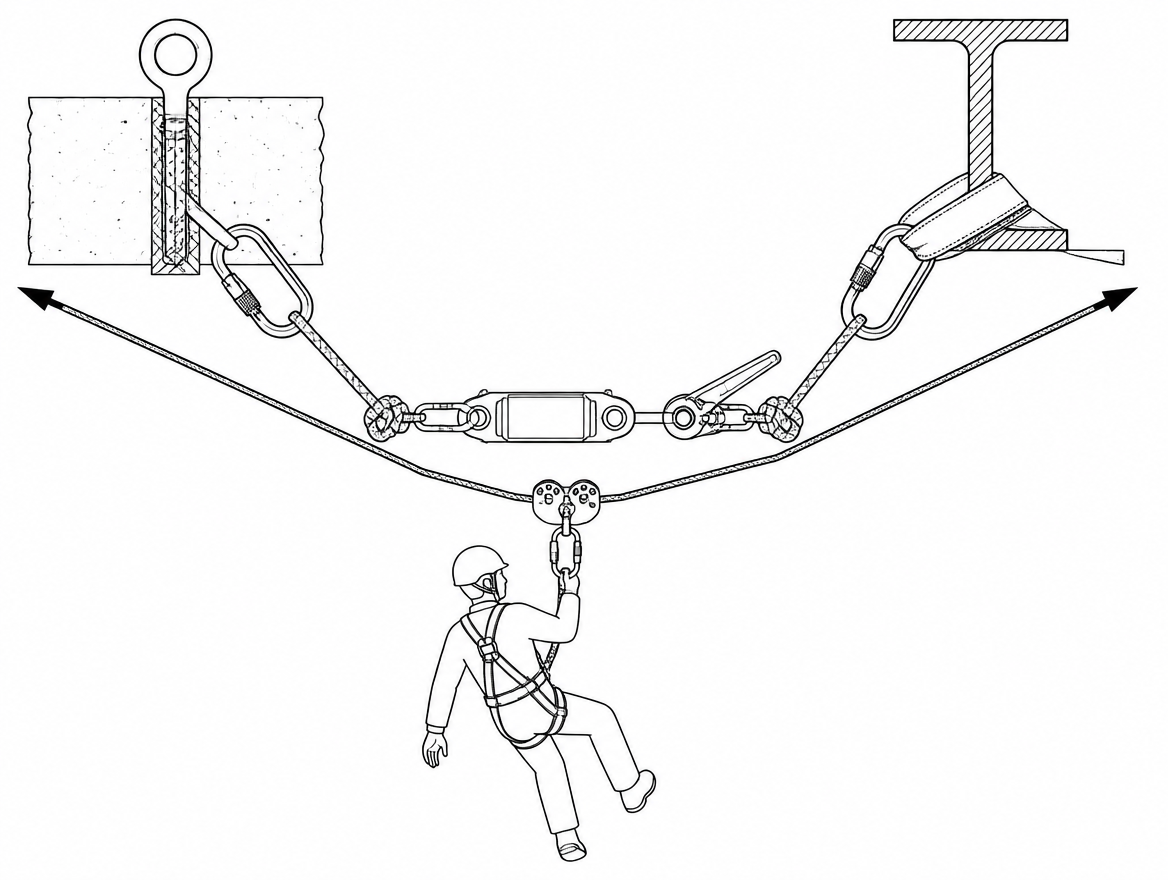
Where the rope passes over a parapet, beam flange, rock lip or cut steel edge, edge protection is not optional. A tensioned rope under movement and vibration will abrade quickly, and the abrasion is concentrated in one spot. Rollers or purpose-made edge protectors, secured independently so they cannot be dragged out of position, are part of the system, not an accessory.
Rope selection and the two-rope principle
Low-stretch kernmantle rope to EN 1891 Type A is the normal choice for the track line and the safety line. Type A rope is tested to a minimum static strength of 22 kN unterminated and 15 kN with figure-of-eight terminations, and to limited elongation between 50 kg and 150 kg loads. Two points follow from that:
- Every knot is a strength reduction. The 15 kN terminated figure quoted in EN 1891 is a useful reminder that the rope’s rating in a real, knotted system is not its catalogue figure.
- Low stretch is desirable for a traverse – a dynamic rope to EN 892 will sag progressively as it creeps under load – but low stretch also means the system absorbs very little energy, so shock loading passes almost directly into the anchors.
The safety line is a separate rope, on separate anchors, tensioned independently. It is not a second strand clipped into the same shackle. In practice the safety line is usually rigged with slightly more sag than the track line so that it is not sharing tension in normal use, but will catch the person with minimal drop if the track line fails.
How the person is attached
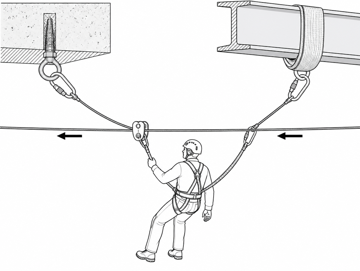
Attachment is where a good traverse is spoiled most often. The arrangement that keeps loading predictable is short, direct and redundant:
- Harness: a sit harness to EN 813 for suspension and ventral attachment, in a combined harness that also provides a fall-arrest attachment to EN 361. On a near-horizontal system the working attachment is normally ventral, keeping the person’s centre of gravity below the trolley.
- Trolley or pulley: a device conforming to EN 12278 for pulleys, or a proprietary traverse trolley used strictly within its instructions. Twin-sheave designs distribute load and run more predictably on a tensioned line than a single small-diameter pulley.
- Connection to the trolley: two independent connectors to EN 362, or one connector plus a redundant sling, so that no single connector failure detaches the person.
- Backup on the safety line: a device suited to the line and the angle. EN 12841 classifies rope adjustment devices as Type A (backup on a safety line), Type B (ascent) and Type C (descent), but most Type A devices are designed and tested on a near-vertical line. On a shallow-angle traverse their gripping behaviour changes, so the device chosen must be one the manufacturer permits for horizontal or low-angle use.
- Tether length: short enough that a failure of the track line produces a small fall and a small swing, and short enough that the person cannot end up out of reach of both lines.
Movement across the span
Three movement methods are used, and the choice affects the whole rig.
- Self-propelled. The person pulls themselves along the track line by hand, or on a steeper angle uses ascenders. Simple, but the operator has no control over their own arrest if they lose grip on a downhill section, so an uphill-side control line is usual.
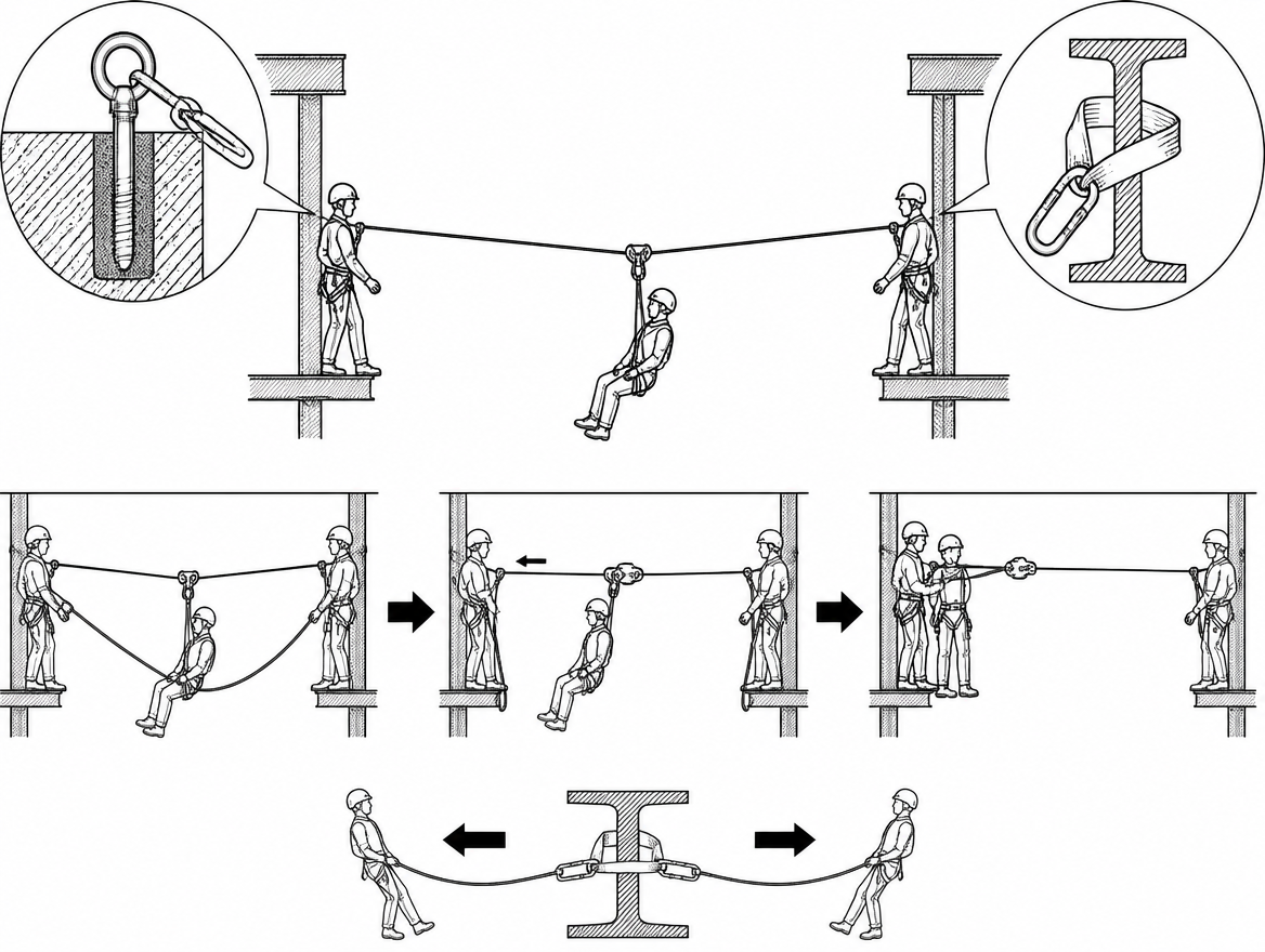
- Hauled by a control line. A team on the far side pulls the person across on a separate rope, with a second line back to the start side for retrieval. This is the normal method for traverses that carry a casualty or a working load, because it keeps positive control at both ends.
- Gravity-fed on a sloping traverse. Anything with a downhill gradient requires a controlled descent: a friction device managed by an operator, not an unregulated slide. Uncontrolled arrival at the far anchor is a common source of injury.
Whichever method is used, the low point of the loaded span must be checked before the traverse is made. A person at mid-span sits far lower than the unloaded rope suggests, and clearances to water, machinery, structure or ground level should be verified with the load on the system, not on paper.
Rescue is part of the rig, not an afterthought
A person stalled at mid-span on a Tyrolean traverse is in one of the harder retrieval situations in rope work: they are suspended, out of reach from both ends, and often unable to self-rescue. Suspension in a harness without the ability to move the legs restricts venous return and can cause rapid deterioration, so the plan has to be measured in minutes.
EN 365 requires that a rescue plan exists for any situation in which personal fall protection equipment is used. ISO 45001 places the same obligation in a management-system frame through clause 8.2 on emergency preparedness and response. For a traverse specifically, the plan should identify:
- which of the two ends the retrieval is run from, and who holds the tail;
- how the tensioning system is released under load and what the resulting sag will be, including any obstruction the person would be lowered onto;
- how a second rescuer reaches mid-span, and whether the anchors are rated for two people simultaneously (see CEN/TS 16415);
- the rescue equipment that is on site and rigged, not the equipment that could theoretically be fetched.
Inspection and records
EN 365 sets the framework for instructions for use, maintenance, periodic examination and marking. Periodic examination by a competent person is required at intervals defined by the manufacturer and at least every 12 months, with the results recorded. For traverse equipment, the pre-use checks that catch the most defects are specific:
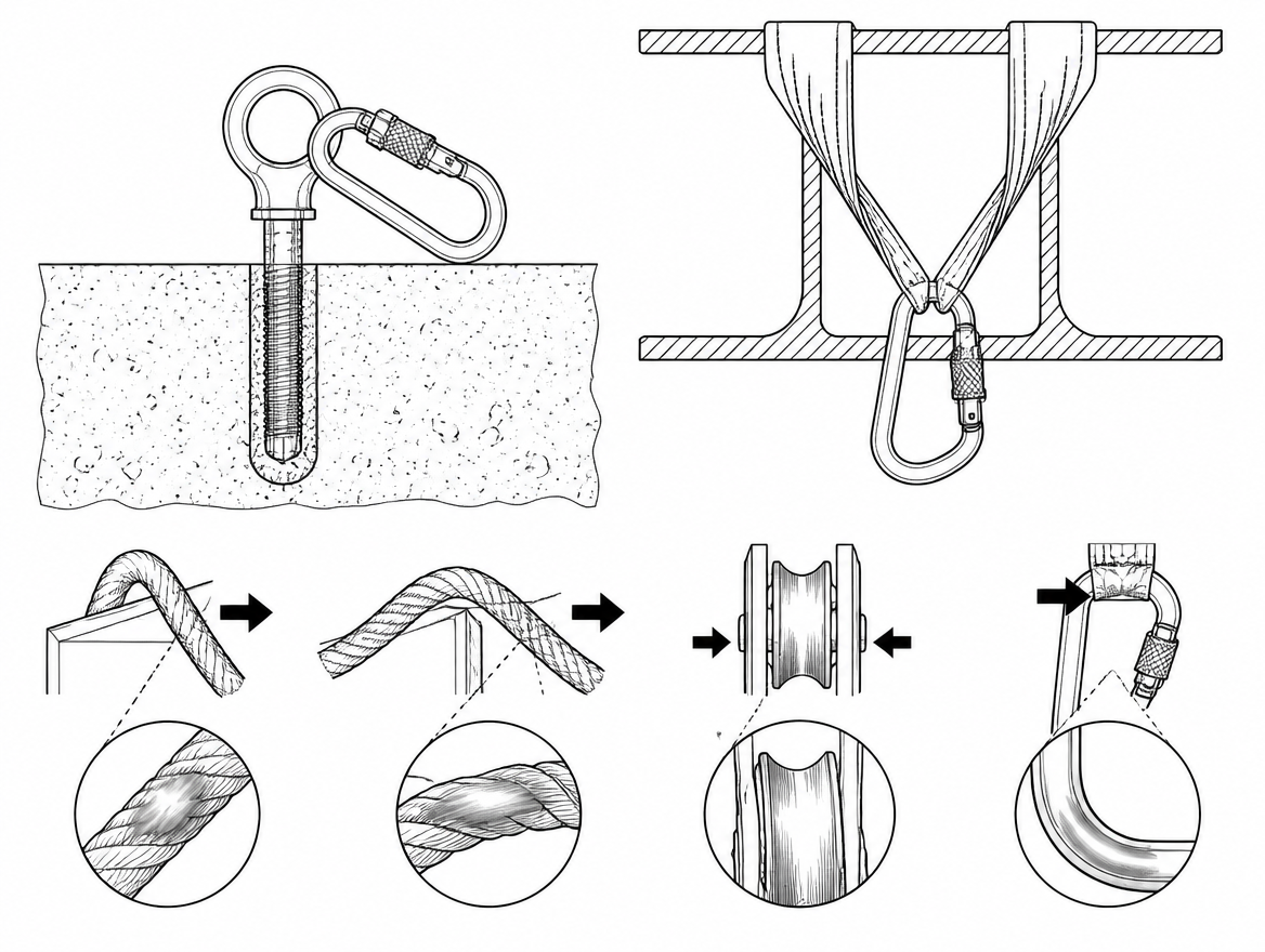
- Rope: run the full length through the hands, checking for glazing, sheath abrasion, core deformation and localised flat spots – particularly the sections that sat over edges or in the tensioning system.
- Pulleys and trolleys: sheave rotation, side plate deformation, axle play, and wear grooves in the sheave that indicate the rope has been running under high tension.
- Connectors: gate function, full locking of the sleeve, absence of grooving at the major-axis bearing surface.
- Anchors: condition of structural attachments, torque and corrosion of installed anchors, and the current certification of any EN 795 device.
- Any component subjected to a shock load or an arrested fall is withdrawn from service pending assessment by a competent person.
Competence and supervision
Building a Tyrolean traverse is not an extension of general work-at-height training. It combines anchor engineering, tension management, mechanical advantage systems and mid-span rescue, and it is subject to the competence requirements of EN ISO 22846-2 and ISO 45001 clause 7.2. Rope access work is not carried out alone: the code of practice is built around teams in which at least one other person is present and capable of performing a rescue.
The short version
Keep at least 10% sag at mid-span under load and measure the tension rather than estimating it. Provide two independent anchor points at each end, sized against rope tension and not body weight. Rig a separate, separately anchored safety line with a backup device the manufacturer approves for low-angle use. Protect every edge the rope crosses. Make the tensioning system releasable under load, and write the mid-span retrieval into the rescue plan before the first crossing.
The next documents to have open when planning a traverse are EN ISO 22846-2 for the code of practice, EN 795 and CEN/TS 16415 for anchor device scope, and the manufacturer’s instructions for every trolley, backup device and tensioning component in the system – particularly the sections that state the permitted rope diameters and the permitted angles of use.
Frequently asked questions
Why is a tight Tyrolean rope more dangerous than one with sag?
Intuition says a tight rope is a safe rope, but the mechanics say the opposite: the flatter the rope, the higher the tension needed to support the same weight, and the higher the load transmitted into both end anchors. For a point load at mid-span the tension in each leg is approximately W / (2 sin θ), where θ is the angle of each rope leg below horizontal. At 2% sag each anchor sees roughly 12.5 times the suspended load; at 10% sag roughly 2.5 times.
How much sag should a Tyrolean traverse have?
A working target of no less than 10% sag at mid-span under load is common practice in rescue and rope access teams. Systems built with a mechanical advantage haul left cranked tight are the ones that break end anchors.
What do the tension multipliers in the article assume?
They are an idealised static case: a point load at mid-span, rope weight ignored, no friction and no dynamic movement. Real systems add the pre-tension already in the rope before anyone loads it, plus any bounce, swing or arrested momentum.
What anchor provision does each end of a traverse need?
Both ends carry the full rope tension, not half of it, so anchors must be sized against the measured or calculated tension with a margin, not against body weight. Redundancy means two independent anchor points at each end, equalised or load-distributed, with sling angles kept narrow — the internal angle between legs of a load-sharing sling should be kept well under 90°. Structural anchors to EN 795 Type A, or verified structural steelwork assessed by a competent person, are the usual basis; Type B and Type E devices are rarely appropriate unless the manufacturer explicitly permits it. Slings to EN 566 and connectors to EN 362 with locking gates complete the chain.
Can an EN 795 Type C horizontal lifeline be used as a Tyrolean track line?
No. A Type C horizontal lifeline is a fall-arrest anchor line for a person clipped beneath it. It is not tested or certified as a track line for traversing on a trolley, and using it that way falls outside the manufacturer's instructions. Multi-person use is also not covered by EN 795 alone — CEN/TS 16415 sets out the test requirements for anchor devices used by more than one person simultaneously, which becomes relevant as soon as a rescuer joins a casualty on the same system.
Need this as a document you can issue? The template library gives you the risk assessments, permits and inspection logs in editable form — and employer plans cover a whole team with completion records.