Safety / Tips and Tricks / Rope access and confined space
Activity 01 · Rope access
Rigging a Releasable Anchor with a Descender
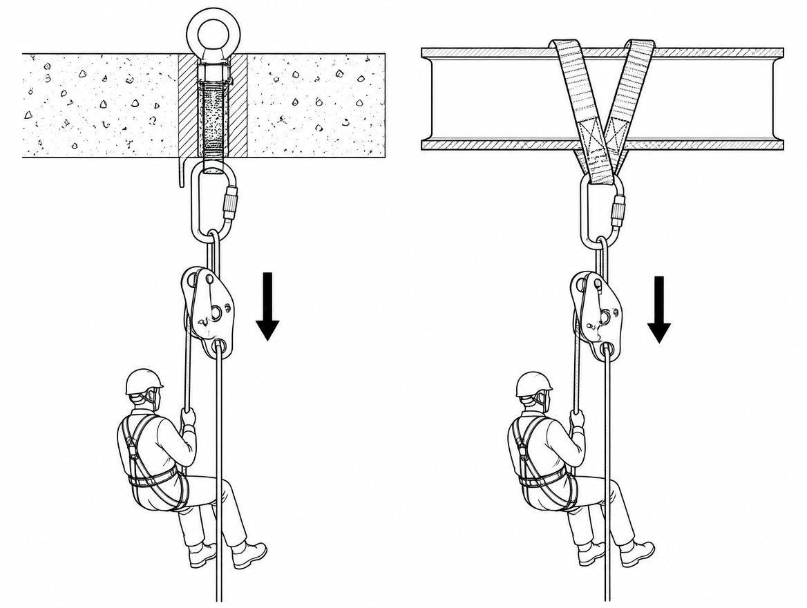
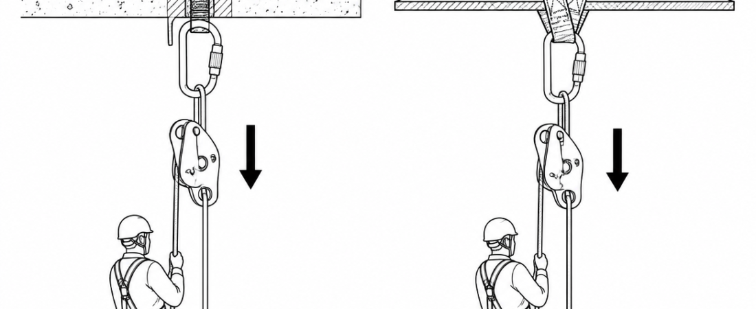
A releasable anchor is the difference between a system that can be lowered under control and a system that has to be cut, dismantled or hauled to release. Rigged correctly, a descender at the anchor lets a tensioned line, a suspended worker or a stretcher be paid out smoothly under load, at any moment, without a load transfer. Rigged badly — rope reversed through the device, tail too short, connector loaded across its minor axis — it becomes a single point that fails exactly when the release is needed. This article covers device selection against EN 12841 and EN 341, the rigging sequence, tail-length arithmetic, friction management for heavy loads, and the checks that belong in a pre-use inspection.
What “releasable” actually means in a rigged system
A conventional anchor is fixed: the rope is tied off or gripped at the anchor and the only way to give slack is to transfer the load onto something else first. A releasable anchor keeps the working end of the rope in a device that can be unlocked and paid out under load, so slack can be delivered progressively and reversibly. Three common on-site reasons for it:
- Converting a haul to a lower. If a raise has to be reversed — wrong direction, an obstruction, a casualty deteriorating — the change of direction is immediate rather than a re-rig.
- De-tensioning a loaded line. Guylines, tensioned traverse lines and tag lines can be brought back to slack in a controlled way instead of being released in one step.
- Recovering a stuck descent or a pick-off. A worker suspended on a jammed device, or a two-person load on one line, can be lowered from the anchor without the rescuer having to break into the loaded system at height.
Note the scope boundary: the descender is a rigging component within the system. It does not turn the structure into a certified anchor device. The attachment point itself still has to satisfy EN 795 (Type A structural anchor, Type B portable anchor, Type D rigid rail, and so on), and where more than one person can be supported by the same anchor device, CEN/TS 16415 is the relevant specification rather than EN 795 alone. Structural adequacy of the underlying steelwork, concrete or timber is a separate engineering question and should be confirmed before anything is clipped to it.
Choosing the descender: EN 12841 Type C, EN 341, or neither
Two European standards cover the devices normally used to build a releasable anchor descender arrangement, and they describe different intended uses:
- EN 12841 Type C — rope adjustment devices for rope access work, in the descender category. These are certified for descent on a working line by one user, up to the maximum rated load in the manufacturer’s instructions. Types A (backup devices) and B (ascenders) in the same standard are not descent devices and must not be substituted.
- EN 341 — descender devices for rescue. The standard sorts devices into classes (A to D) according to the descent work and the load and descent-height range they are tested for. A device certified only for rope access descent may carry a separate, higher rescue rating under EN 341 in the same instruction manual; a device with no EN 341 marking has not been tested for that duty.
Practical consequence: for a rescue or two-person load, the permitted mass is whatever the manufacturer states for that specific mode of use — not the single-user figure, and not a number carried over from another brand. Where the intended load exceeds the device’s rated range, the correct answer is a different device or an additional friction element, not optimism.
Compatibility checks that belong in the same decision:
- Rope diameter and type. Use a low-stretch kernmantle rope to EN 1891 (Type A for most work-at-height and rescue rigging) within the diameter range printed in the device’s instructions. A rope at the bottom of the stated range slips more; a rope at the top of it feeds harder and can bind under load.
- Rope condition. Wet, muddy, iced or heavily used sheath changes the friction the device delivers. Assume less control, not more.
- Connectors. Locking connectors to EN 362, of a class suited to the attachment (for example Class A for direct attachment to an anchor, Class Q screwlink fully closed).
- Anti-panic and self-braking function. Devices with an anti-panic feature stop feeding if the handle is pulled too far. That is a benefit for descent control and a nuisance if the operator does not know the handle travel; it must be understood before it is used under load.
Rope orientation is the failure mode that hides in plain sight
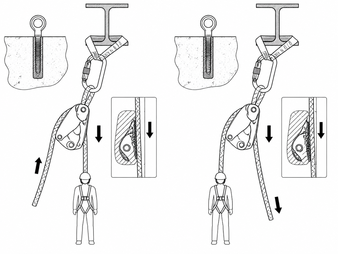
Every self-braking descender has a load side and a controlled (free) side. Reversing them defeats the camming action, and on some designs the device will still hold a static hand-load, so the error is not obvious until real load arrives. Route the rope by the pictogram moulded into the device body every time, including when re-rigging in the dark or in gloves, and confirm the routing with a hand-load before committing the system.
The rigging sequence
- Confirm the anchor. Verified structural point, or an anchor device appropriate to the load and number of persons (EN 795 / CEN/TS 16415). Check the direction of pull the anchor will actually see once the system is loaded, not the direction it sees while being rigged.
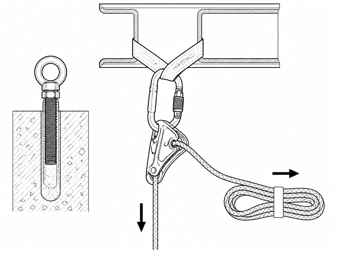
- Attach the anchor connection. Anchor strap or sling rated for the use, connected with a locking connector to EN 362. Keep the sling clear of sharp flanges, weld spatter and edges; pad or edge-protect where contact is unavoidable.
- Install the descender in the correct orientation so the handle is accessible, the moving parts are not fouled by the structure, and the device can align with the load line without the frame levering against steelwork.
- Load the rope per the pictogram, close and lock the device, and check that the cam engages.
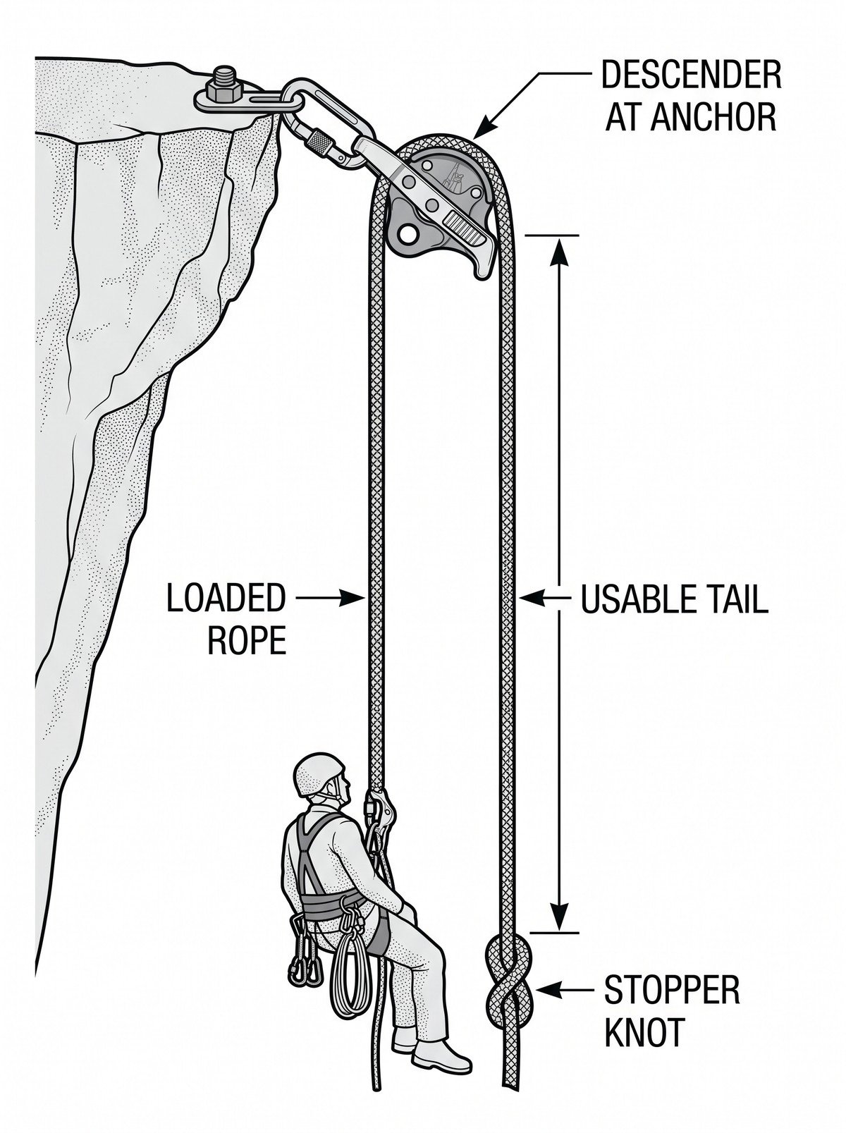
- Manage the tail. Terminate the free end with a stopper knot and keep the tail bagged or coiled so it cannot snag, blow into machinery, or fall into the work area below.
- Add the friction or backup elements the load requires (see below) before the system is loaded, not after.
- Lock off. Use the device’s designed locked position and, if the manufacturer permits it, a tie-off on the free side so the anchor cannot be released by an accidental knock to the handle.
- Test-load and observe. Bring the load on gradually and watch for creep, rope slip through the device, and any movement of the anchor connection. Then brief whoever will operate the release.
One person should be nominated as the operator of the releasable anchor, positioned so they can see or hear the load, with a clear communication method agreed in advance. An unattended handle on a loaded system is not a rigged anchor — it is a hazard.
Tail length sets your release distance
The maximum controlled release is limited by the rope available on the free side of the device, minus a reserve. Work it out before rigging rather than discovering it mid-lower:
- Identify the distance the load actually needs to travel — to the ground, to a landing, or to the point where a tensioned line goes slack.
- Add rope for the stopper knot and a working reserve so the operator is never lowering on the last metre.
- Where the rope also passes through a redirect or additional friction device, allow for the rope consumed in those bends.
If the available tail cannot cover the full travel, the system is a partial-release anchor and everyone involved needs to know that, along with the plan for what happens at the end of the tail — a knot pass, a second rope, or a re-rig. The stopper knot is not a plan; it is what stops an unplanned exit.
Friction management for heavy and rescue loads
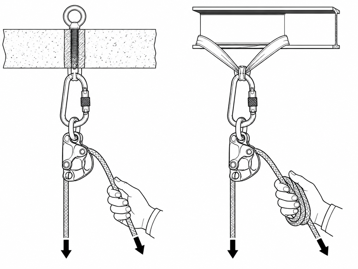
A device that gives comfortable control with one person on the line can be difficult to hold, and can descend faster than intended, with a two-person rescue load. Increasing friction outside the device keeps the operator in control:
- Braking carabiner on the free side, where the manufacturer’s instructions permit it — the standard method of adding friction to many self-braking descenders.
- Redirect at the anchor to change the angle at which the rope leaves the device, which also changes how the device sits under load.
- A dedicated higher-capacity device where the load is outside the rated range for the one in hand.
Gloves suited to rope handling, a clean rope path, and a second person tending the tail all contribute more to control than muscle does. Heat is a genuine consideration on long lowers: aluminium bodies and rope sheaths both warm up, and the friction that gives control is also what generates that heat.
Connector and lock-off detail
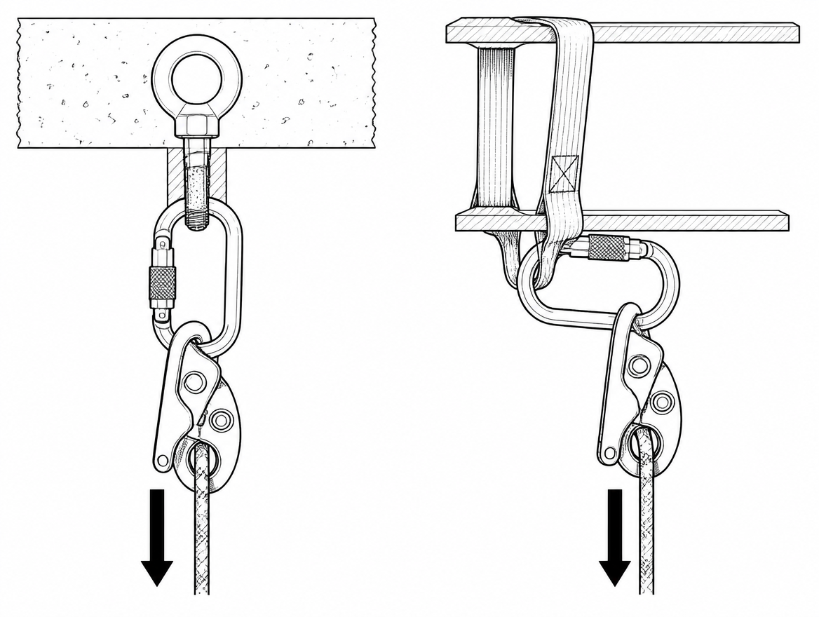
Most of the small errors that undermine an otherwise sound releasable anchor sit at the connector:
- Loaded along the major axis, gate closed and locked — not cross-loaded against a beam flange or bracket.
- Gate not resting against the structure, where movement of the system could unscrew or unlock it.
- Free to align with the load, rather than pinned in a position that levers the descender body.
- Screwgate fully closed; twist-lock and triple-action gates checked by hand rather than by eye.
Redundancy: the releasable anchor is not the only line
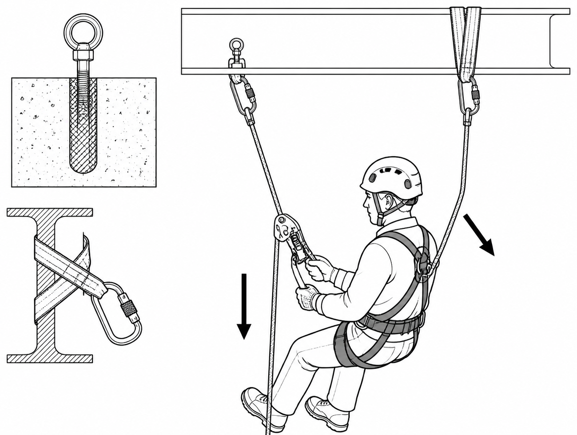
EN ISO 22846-2 sets out the two-rope working principle for rope access: a working line and an independent backup line, each with its own anchor. Building a releasable anchor does not suspend that principle. In practice:
- Anchor the working line and the backup line to independent points where the structure allows it, so releasing or losing one does not compromise the other.
- Keep the backup device on the second line clear of the release path so that paying out the working line does not load or jam the backup unpredictably.
- Where a casualty is being lowered, use rescue-specific equipment for the casualty attachment — a rescue harness to EN 1497 or a rescue loop to EN 1498 as appropriate to the situation and the training held.
Inspection, records and competence
EN 365 sets the framework for instructions for use, marking, periodic examination and records for personal fall protection equipment. For a releasable anchor built from a descender, rope and connectors, that means:
- Pre-use check of the device body for cracks and deformation, the cam and its pivot for wear and free movement, the moving side plate and locking mechanism, and the rope for sheath damage, glazing, flat spots and core inconsistency along its length.
- Periodic examination by a competent person at least every 12 months, more frequently where use is intensive or the environment is aggressive (grit, salt, chemicals, UV exposure). National regulations and manufacturer instructions may require shorter intervals.
- Traceable records for each item: identification, date of first use, examination history and outcome, and the retirement decision when it comes. Retirement criteria and any stated maximum service life come from the manufacturer, not from consensus on site.
- Documented competence. The person rigging and operating the release should be trained on that specific device family, including handle travel, anti-panic behaviour and lock-off method.
At management-system level, a releasable anchor usually exists because a rescue or lowering scenario has been anticipated. That anticipation belongs in the emergency preparedness and response arrangements required by ISO 45001 (clause 8.2) — with the equipment listed, the responders identified, and the plan tested rather than filed.
Pre-load checklist
- Anchor verified for the load and the direction of pull; correct anchor device standard for the number of persons.
- Descender certified for the intended use (EN 12841 Type C for work descent, EN 341 for rescue duty) and within its rated load for that mode.
- Rope to EN 1891 within the device’s stated diameter range; condition inspected along the whole working length.
- Rope routed per the device pictogram; cam engagement confirmed under hand-load.
- Connectors to EN 362, locked, loaded on the major axis, free to align.
- Tail length ≥ required travel plus reserve; stopper knot tied; tail bagged and clear of hazards.
- Additional friction fitted if the load requires it, in a configuration the manufacturer permits.
- Device locked off; nominated operator in position; communication method agreed.
- Independent backup line rigged and clear of the release path.
- Edge protection in place wherever rope or sling contacts structure.
The takeaway
A releasable anchor buys one thing: the ability to give slack under load, on demand, in a controlled way. That value depends entirely on details that are quick to check and expensive to skip — the correct device for the actual load, rope routed the correct way round, a tail long enough for the travel required, and a connector loaded the way it was designed to be loaded. Before rigging, read the specific instructions for the device in hand alongside EN 12841 and EN 341, and confirm the anchor against EN 795 or CEN/TS 16415 as the number of persons requires. Where the numbers do not add up — rated load, rope diameter, tail length — change the system, not the assumption.
Frequently asked questions
What makes an anchor "releasable"?
A releasable anchor keeps the working end of the rope in a device that can be unlocked and paid out under load, so slack can be delivered progressively and reversibly. A conventional fixed anchor has the rope tied off or gripped at the anchor, so the only way to give slack is to transfer the load onto something else first.
Why would you rig a releasable anchor on site?
Three common reasons are given: converting a haul to a lower, so a raise can be reversed immediately rather than re-rigged; de-tensioning a loaded line such as a guyline, tensioned traverse line or tag line in a controlled way instead of one step; and recovering a stuck descent or pick-off, so a suspended worker or a two-person load can be lowered from the anchor without the rescuer breaking into the loaded system at height.
Does putting a descender at the anchor make the structure a certified anchor?
No. The descender is a rigging component within the system and does not turn the structure into a certified anchor device. The attachment point still has to satisfy EN 795 (Type A structural, Type B portable, Type D rigid rail, and so on), and where more than one person can be supported by the same anchor device, CEN/TS 16415 is the relevant specification rather than EN 795 alone. Structural adequacy of the underlying steelwork, concrete or timber is a separate engineering question to confirm first.
What is the difference between EN 12841 Type C and EN 341 for this use?
EN 12841 Type C covers rope adjustment devices in the descender category, certified for descent on a working line by one user up to the maximum rated load in the manufacturer's instructions; Types A (backup devices) and B (ascenders) are not descent devices and must not be substituted. EN 341 covers descender devices for rescue and sorts devices into classes A to D according to the descent work and the load and descent-height range tested. A device with no EN 341 marking has not been tested for that duty, and the permitted mass for a rescue or two-person load is whatever the manufacturer states for that specific mode of use.
Why is rope orientation through the descender such a serious error?
Every self-braking descender has a load side and a controlled (free) side, and reversing them defeats the camming action. On some designs the device will still hold a static hand-load, so the mistake is not obvious until real load arrives. The article advises routing the rope by the pictogram moulded into the device body every time — including when re-rigging in the dark or in gloves — and confirming the routing with a hand-load before committing the system.
Need this as a document you can issue? The template library gives you the risk assessments, permits and inspection logs in editable form — and employer plans cover a whole team with completion records.