Home / Rope Access Work-Positioning Fundamentals: Twin Ropes, Attachment Points and Controlled Movement
Rope Access Work-Positioning Fundamentals: Twin Ropes, Attachment Points and Controlled Movement
Rope access puts a technician exactly where the work is — a facade joint, a weld on a mast, a bearing under a bridge deck — without the erection time, footprint or loading of scaffold or a suspended platform. The trade-off is that every second of that access depends on a small, deliberately redundant set of components: two independently anchored ropes, two independent devices, one harness, and a technician who understands how load moves through all of it. This article covers the positioning fundamentals that sit underneath every rope access task: what the two-rope rule actually requires, where each device belongs on the harness, how anchorage is separated at the top, and how a technician moves under control while remaining attached throughout.
Work positioning is not fall arrest, and the distinction changes the hardware
Three regimes are routinely confused on site:
- Restraint — the system physically prevents the worker from reaching a fall edge. No fall is possible, so no energy absorption is needed.
- Work positioning — the worker is supported by the system while working, hands free, with the system kept taut so any fall is minimal. Positioning belts and lanyards to EN 358 are designed for this, and are not fall arrest equipment.
- Fall arrest — a fall is possible and the system is designed to stop it within survivable limits, using an EN 361 full-body harness and an energy-absorbing subsystem.
Rope access sits mostly in the second category but must always carry the third as a fallback. The technician’s weight is carried by the working line through a descender; the backup line carries no load until something on the working side fails. That is why the two lines are not interchangeable and why a single rope with two devices on it is not a rope access system.
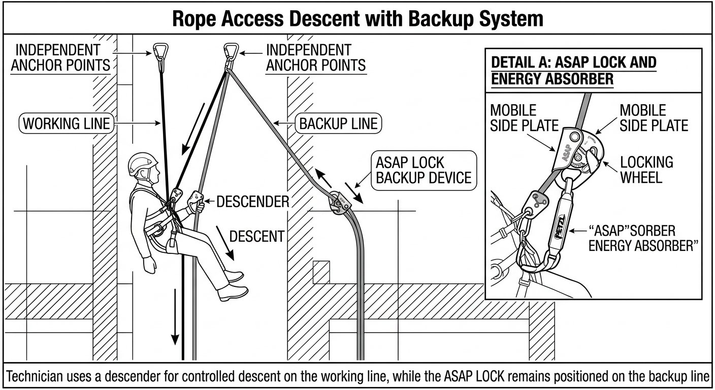
Two independently anchored ropes: the working line carries the load, the backup line stays unloaded until it is needed.
The two-rope rule and where it comes from
In the EU, the temporary work at height provisions introduced by Directive 2001/45/EC and now consolidated in Directive 2009/104/EC set the baseline for rope access and positioning techniques: the system must comprise at least two separately anchored lines, one serving as the means of access, descent and support (the working line) and the other as backup (the safety line). The worker must wear and be attached to a harness connected to the safety line. Where prolonged suspension is involved, a seat with appropriate accessories is required, and the work must be properly planned, supervised and carried out by adequately trained workers. National implementations may permit a single rope only where a risk assessment shows that a second line would make the work more dangerous, and only with compensating measures.
Industry codes tighten this further. IRATA’s International Code of Practice and ISO 22846-1/-2 both build on the same principle — two independent systems, continuous attachment, and a team structure in which no technician works alone. Certification schemes (IRATA Levels 1–3, SPRAT Levels I–III) exist to evidence the competence the legislation assumes.
Harness attachment points: ventral, sternal, lateral
A rope access harness is usually a combined EN 361 fall arrest harness with an EN 813 sit harness element, often with EN 358 lateral attachment points as well. Each point has one job:
- Ventral (EN 813, low front) — carries the descender or ascender on the working line. This is the point that takes the technician’s weight in normal suspension and gives the seated posture that keeps the hands free.
- Sternal or dorsal (EN 361) — fall arrest attachment. The backup device is typically connected here via a short manufacturer-supplied lanyard, keeping the device high on the safety line and the potential fall short.
- Lateral pair (EN 358) — used together with a positioning lanyard when the technician is standing on a structure rather than hanging, for example on a tower leg or a ladder cage. These points are for positioning only and must never be used for fall arrest.
The devices themselves are governed by EN 12841, which classifies rope adjustment devices for rope access by function: Type A backup devices for the safety line, Type B ascenders for the working line, and Type C descenders for the working line. Type C descenders are certified with specific rope diameters and constructions — normally EN 1891 Type A low-stretch kernmantle rope — and the manufacturer’s stated diameter range is a hard limit, not a recommendation. Mixing a device with an out-of-range rope changes braking behaviour in ways that are not visible until load is applied.
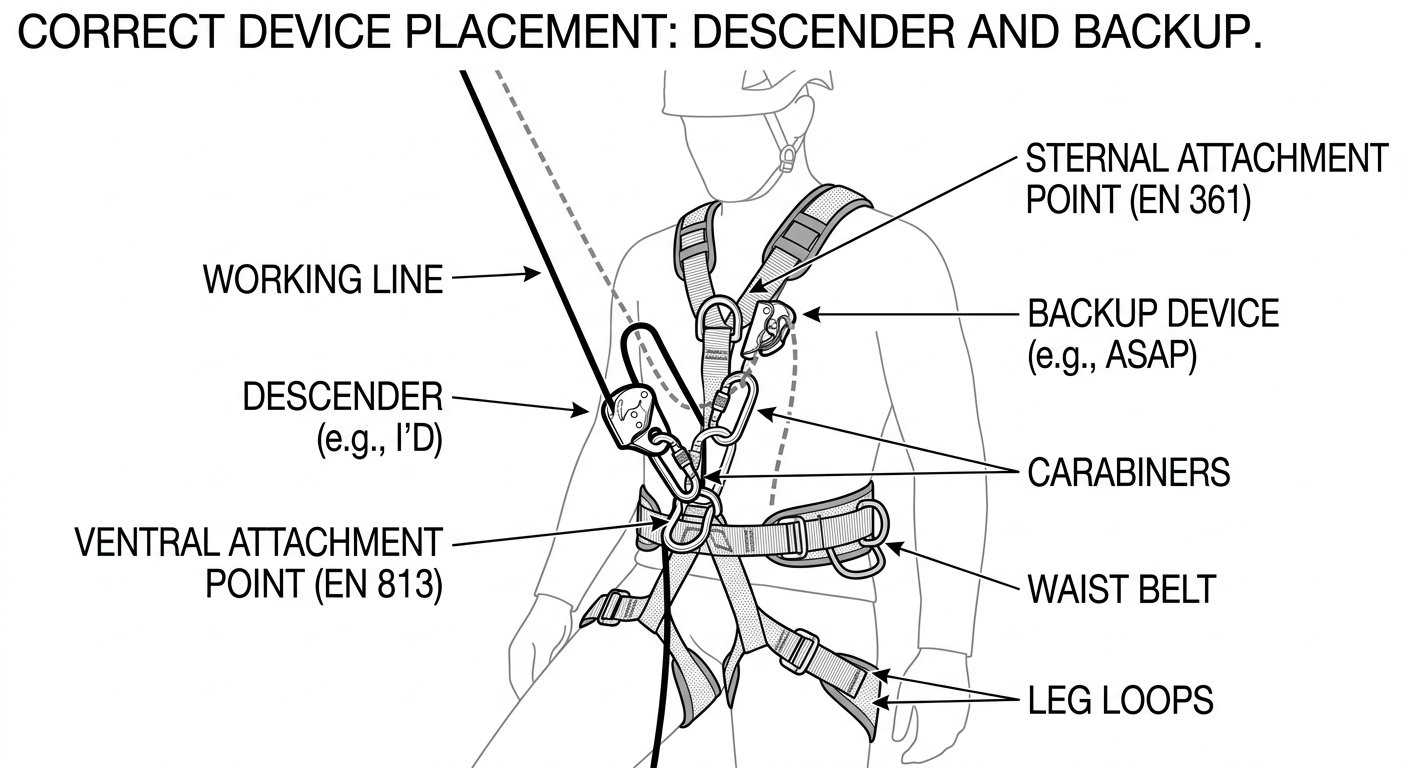
Correct device placement: descender on the ventral EN 813 point, backup device on the safety line at the sternal attachment.
Separated anchorage at the top edge
Redundancy at the harness is worthless if both ropes trace back to the same bolt. The working line and the safety line must be anchored independently, so that failure of one anchorage, connector or rigging component cannot release both.
Practical points that decide whether a top rig is sound:
- Anchor devices should conform to EN 795 (types A–E) and, where more than one person may load a device at the same time, to CEN/TS 16415. Structural anchor points that are part of the building are assessed by a competent person against the loads they will actually see, in the directions they will actually be loaded.
- Direction of pull matters as much as rating. A parapet eyebolt rated for a downward pull can behave very differently under a sideways or upward load created by a deviation.
- Rigging plates and connectors should be arranged so that load paths are legible at a glance — a rig that has to be explained is a rig that will be misread on a bad day.
- Edge protection is not optional. Rope protectors, edge rollers or padded canvas are placed wherever a loaded rope crosses masonry, metal flashing, glass edges or a coping stone. Both ropes need protecting, not just the working line, and protection must stay put when the rope moves.
- Rope ends are terminated with a stopper knot and, where the rope reaches the ground or a landing, kept clear of traffic, hot work and moving plant.
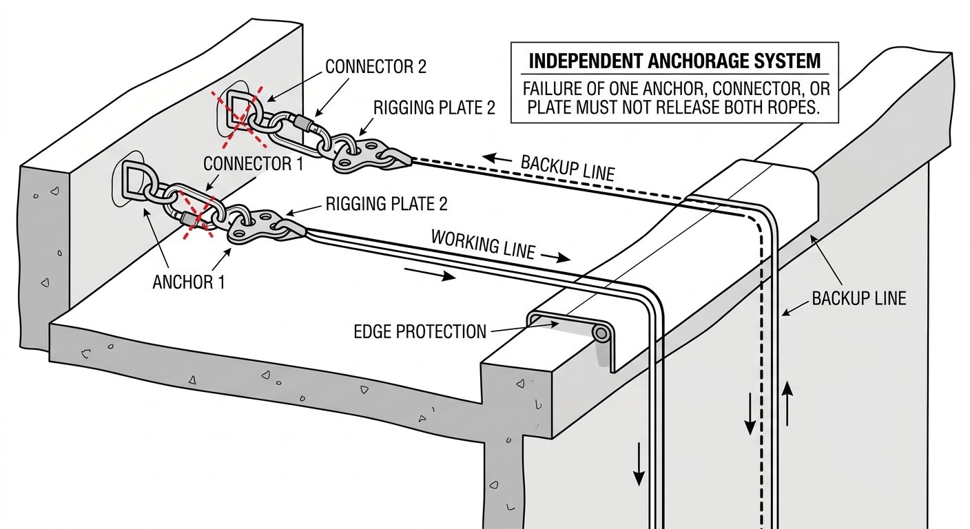
Separated anchorage: failure of one anchor, connector or plate must not release both ropes.
Descent, ascent and lateral movement under control
Movement on rope is a sequence of deliberate, reversible actions. The technician is never in a state where releasing a hand causes uncontrolled travel.
Descent
The descender is loaded on the ventral attachment, the brake-side rope is held below the device at all times, and speed is regulated by the brake hand rather than by the control handle alone. Modern EN 12841 Type C descenders include an anti-panic function that engages if the handle is pulled too far, but that function is a backstop, not a speed control. The backup device is pushed down the safety line as descent progresses so it never trails slack above the technician. Stopping means locking off the descender so the system holds the load without hand pressure, before beginning any task.
Ascent
Ascent uses a chest ascender and a handled ascender on the working line, with foot loops, and the same Type A backup on the safety line. The backup device is advanced with each stride; a backup left low is the most common way a well-equipped technician creates a real fall distance for themselves.
Deviations and re-anchors
A deviation uses an intermediate anchor to pull both ropes off their natural line — to reach a facade bay, to clear an obstruction or to keep ropes off an abrasive edge. It changes the rope angle but not the continuity of the rope. A re-anchor (rebelay) breaks the ropes at an intermediate anchorage, shortening the free-hanging length and isolating the section above. Both require the technician to pass the anchor while remaining attached by at least two independent points throughout the transfer. That principle — attach before you detach — is the whole of rope access safety compressed into four words.
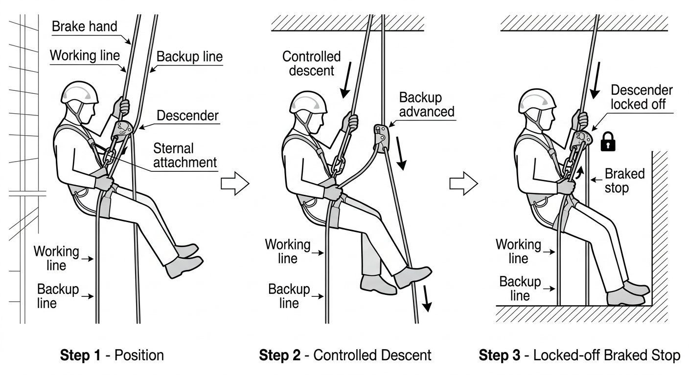
Controlled descent in three steps: brake hand below the device, backup advanced during descent, descender locked off before working.
Holding position at the workface
Once at the work location, the objective is a stable, hands-free posture that does not depend on muscular effort:
- Lock off the descender and confirm the lock holds before releasing the brake hand.
- Add a short positioning lanyard or a foot loop where the task requires a specific body angle, particularly for overhead work or for pushing against a facade.
- Use a work seat for tasks lasting more than a short period. Prolonged suspension in a sit harness alone restricts circulation and degrades both comfort and decision-making.
- Tether tools and secure loose items. Dropped-object controls — tool lanyards, containers and closed buckets, consistent with ANSI/ISEA 121 practice — protect the exclusion zone below and are part of the rigging plan, not an afterthought.
- Keep the backup device positioned so that any slip on the working line is caught with minimal travel.
Rescue capability is part of the system, not a separate plan
A suspended technician who becomes unresponsive cannot be left on rope while help is summoned; suspension intolerance can develop in a motionless casualty far faster than most emergency services can reach a roof and rig. For this reason rope access teams operate with a minimum of two technicians, at least one of whom holds supervisory-level certification, and with rescue equipment already rigged or immediately available for the specific configuration in use. The rescue method must be rehearsed for the actual site: a plan that works on a clean facade may be unusable inside a confined shaft or under a bridge soffit.
Pre-use checks that catch most defects
Personal fall protection equipment requires a documented periodic examination by a competent person — commonly at least every 12 months, and more often where use is intensive or the environment aggressive — alongside a pre-use check by the technician before every session:
- Rope: run the full length through the hands. Look for sheath glazing, cuts, flat or soft spots indicating core damage, chemical staining and heat marks. Check that the length, diameter and standard marking match the devices in use.
- Harness: webbing cuts, abrasion, UV degradation, stitching integrity, buckle function, and legible identification and inspection markings.
- Descender and backup device: free movement of cams and side plates, no cracks or deep grooving in the rope channel, springs functioning, correct rope path when threaded.
- Connectors: gate closes and locks fully, no lateral play, no gate loading in the intended configuration.
- Anchorage: visual check of bolts, plates, slings and edge protection at the start of each shift and after any change to the rig.
Anything that fails a check is quarantined and tagged, not returned to the bag to be reassessed later.
The takeaway
Rope access positioning reduces to four checkable conditions: two ropes on two independent anchorages, one load-bearing device and one backup device on their correct harness attachment points, ropes protected everywhere they touch structure, and a rescue capability on site that matches the configuration. If any one of those is missing, the redundancy that makes the technique acceptable has already been spent.
For the next step, review the rigging and anchorage section of the IRATA International Code of Practice alongside ISO 22846-2, and confirm that the device and rope pairings in your kit are the ones named in the manufacturer’s EN 12841 certification — that single check resolves a surprising share of field non-conformities.
Frequently asked questions
What is the difference between restraint, work positioning and fall arrest?
Restraint physically prevents the worker from reaching a fall edge, so no fall is possible and no energy absorption is needed. Work positioning supports the worker while working with hands free, keeping the system taut so any fall is minimal — positioning belts and lanyards to EN 358 are designed for this and are not fall arrest equipment. Fall arrest assumes a fall is possible and stops it within survivable limits using an EN 361 full-body harness and an energy-absorbing subsystem. Rope access sits mostly in the work positioning category but must always carry fall arrest as a fallback.
What does the two-rope rule actually require?
In the EU, the temporary work at height provisions introduced by Directive 2001/45/EC and now consolidated in Directive 2009/104/EC require at least two separately anchored lines: one serving as the means of access, descent and support (the working line) and the other as backup (the safety line). The worker must wear and be attached to a harness connected to the safety line. Where prolonged suspension is involved, a seat with appropriate accessories is required, and the work must be properly planned, supervised and carried out by adequately trained workers. National implementations may permit a single rope only where a risk assessment shows a second line would make the work more dangerous, and only with compensating measures.
Which harness attachment point takes the descender, and which takes the backup device?
The ventral point (EN 813, low front) carries the descender or ascender on the working line; this is the point that takes the technician's weight in normal suspension and gives the seated posture that keeps the hands free. The backup device is typically connected to the sternal or dorsal EN 361 fall arrest attachment via a short manufacturer-supplied lanyard, keeping the device high on the safety line and the potential fall short. The lateral EN 358 pair is used with a positioning lanyard when standing on a structure, for example a tower leg or ladder cage, and must never be used for fall arrest.
How does EN 12841 classify rope access devices?
EN 12841 classifies rope adjustment devices for rope access by function: Type A backup devices for the safety line, Type B ascenders for the working line, and Type C descenders for the working line. Type C descenders are certified with specific rope diameters and constructions — normally EN 1891 Type A low-stretch kernmantle rope — and the manufacturer's stated diameter range is a hard limit, not a recommendation. Mixing a device with an out-of-range rope changes braking behaviour in ways that are not visible until load is applied.
Why must the working line and safety line be anchored separately?
Redundancy at the harness is worthless if both ropes trace back to the same bolt. The two lines must be anchored independently so that failure of one anchorage, connector or rigging component cannot release both. Anchor devices should conform to EN 795 (types A–E) and, where more than one person may load a device at the same time, to CEN/TS 16415. Structural anchor points forming part of the building must be assessed by a competent person against the loads and directions they will actually see, since a parapet eyebolt rated for a downward pull can behave very differently under a sideways or upward load created by a deviation. Rigging plates and connectors should be arranged so load paths are legible at a glance, and edge protection is placed wherever a loaded rope crosses masonry, metal flashing, glass edges or a coping.
Need this as a document you can issue? The template library gives you the risk assessments, permits and inspection logs in editable form — and employer plans cover a whole team with completion records.