Safety / Tips and Tricks / Rope access and confined space
Activity 01 · Rope access
Connector Locking Systems Compared: Screw-Lock, Two-Stage and Three-Stage Auto-Lock
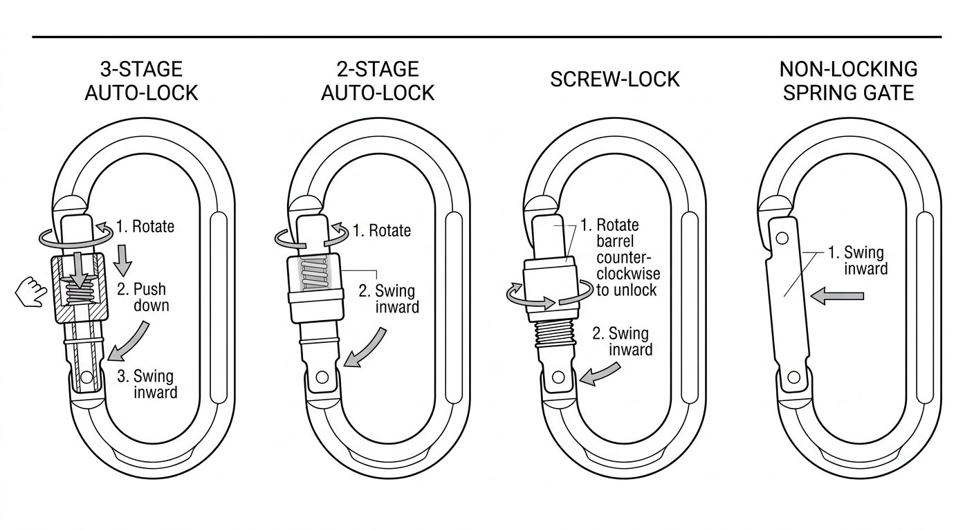
Every rope access or confined-space system comes down to a handful of small metal parts that hold the whole thing together. The connector at the harness attachment point, at the anchor, on the descender and on the back-up device is where a system most often fails through human error rather than material failure — a sleeve left half-turned, a gate pressed against a beam flange, a connector rolled onto its minor axis inside a tight anchor eye. Choosing the right locking system, and knowing how to confirm it is actually locked, is a routine daily task with a very short margin for error.
This article compares the locking mechanisms in common use — manual screw-lock, two-stage auto-lock, three-stage auto-lock — and explains where non-locking connectors do and do not belong.
What “locking” means under EN 362 and EN 12275
Two European standards are relevant, and they are not interchangeable. EN 362 covers connectors for personal fall-protection systems: harness attachment, anchor connection, connection to work and back-up lines. EN 12275 covers connectors for mountaineering, which are frequently found on site because they are lighter, cheaper and readily available, but which are certified against a different use case.
For any connector used at a critical connection point, both standards require a gate that locks — the mechanism must hold the gate closed rather than relying on the spring alone. EN 362 also requires that opening a locked connector takes at least two distinct, deliberate manual actions. That requirement is the reason no compliant locking connector opens with a single pull: it always involves some combination of turning, sliding, pushing and only then opening.
Where equipment is specified against EN 362, use EN 362 connectors. A connector marked only to EN 12275 has been tested to a mountaineering-specific regime and may not carry the markings, classes (A for anchor, B for basic, M for multi-use, T for termination, Q for screwlink) or gate behaviour a fall-protection system requires.
Two-stage auto-locking: twist and open
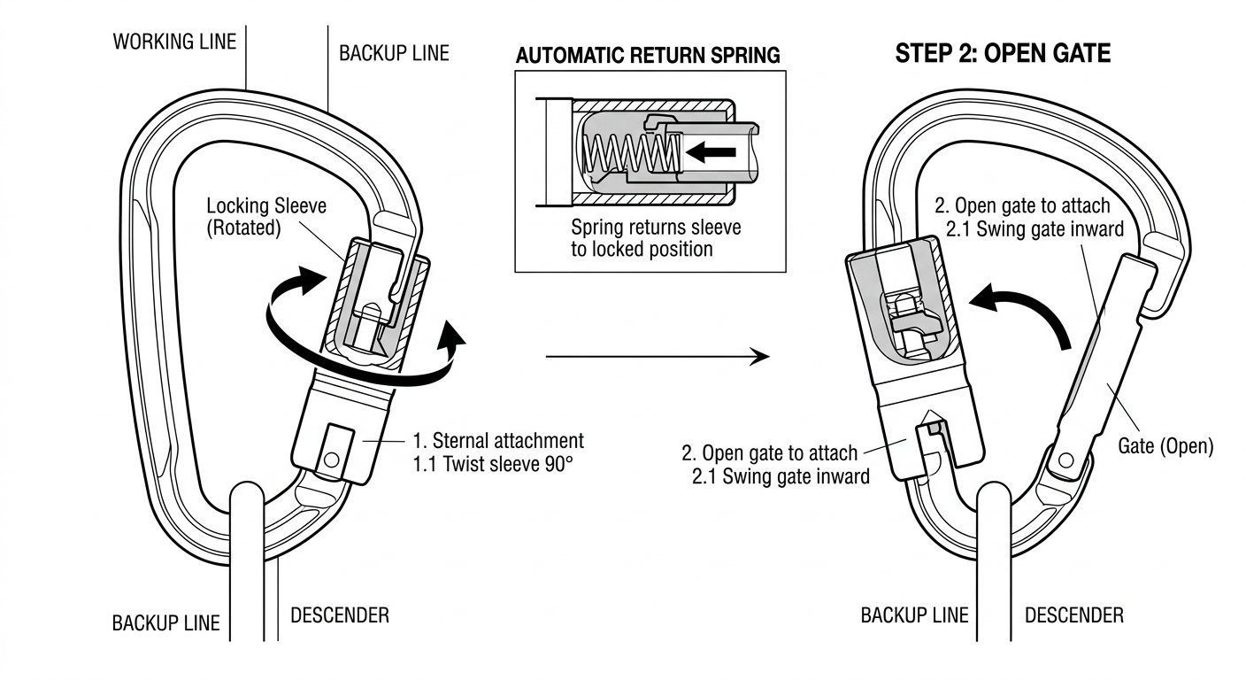
A two-stage auto-locking connector has a sleeve that must be rotated before the gate will open — typically a twist of the barrel, then a push or pull on the gate itself. Release the connector and a spring returns the sleeve to the locked position on its own. Nothing depends on the user remembering a final step.
Strengths: fast, operable with one gloved hand, and self-locking by design. For a technician making and breaking connections repeatedly during a descent or a re-belay pass, the reduction in cognitive load is real.
Limitations: the twist-then-open motion is close enough to a natural gripping movement that it can, in some geometries, be produced accidentally — for example where the connector is pressed sideways against rope, webbing, netting or a structural edge that applies simultaneous rotation and pressure to the gate. Two-stage connectors are widely used and entirely appropriate for most rope access connections, but they suit locations where the connector hangs free rather than sits jammed against a surface.
Three-stage auto-locking: a movement you cannot make by accident
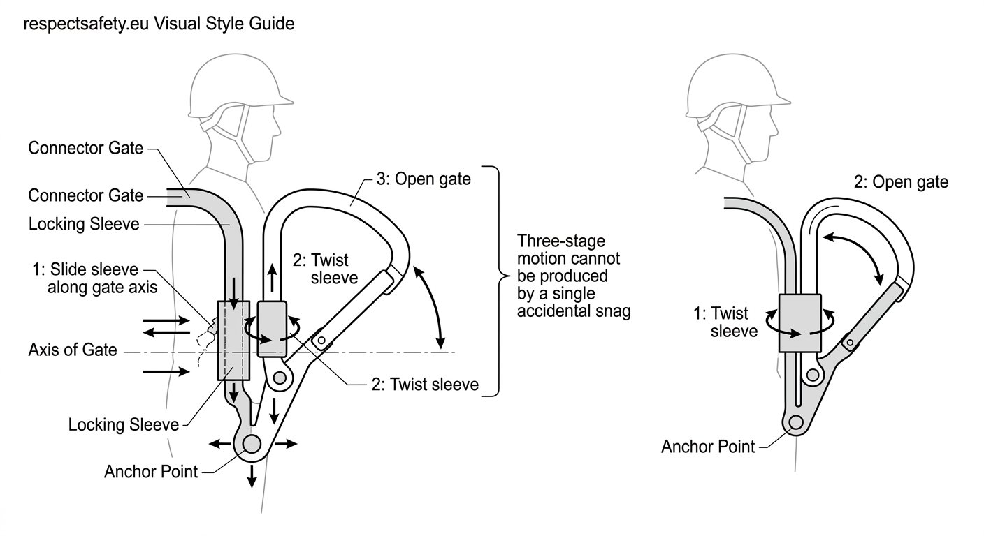
Three-stage mechanisms add a third, non-parallel motion. The most common arrangement is push-down-then-twist-then-open (or slide-up, twist, open): the sleeve must first travel along the axis of the gate before it can be rotated, and only then will the gate move. Because the required actions run in different directions, an incidental snag or a single sideways press cannot reproduce them.
Strengths: the highest resistance to accidental opening of any commonly used mechanism, which is why three-stage connectors are frequently specified for the harness attachment point, for long-duration connections, and for confined-space work where the connector may be dragged against surfaces the technician cannot see.
Limitations: slower to operate, more awkward with heavy gloves or cold hands, and unforgiving of contamination — grit and dried mud in the sleeve track are more disruptive here than on a simpler mechanism. Where a technician has to make many transitions in sequence, some teams accept two-stage connectors for working connections and reserve three-stage for the connections that are made once and left.
Screw-lock: simple, robust, and dependent on the user
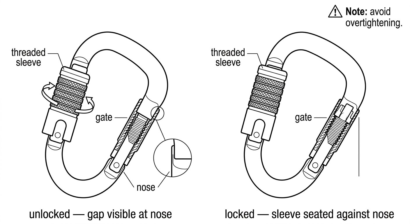
A screw-lock (screwgate) connector has a threaded sleeve that the user winds along the gate by hand until it seats against the nose. There is no spring return; the connector is locked only because someone locked it, and it stays locked only until something unwinds it.
Strengths: few moving parts, tolerant of dirt, easy to inspect visually, and the locked state can be seen at a glance from a distance. Screw-locks are well suited to semi-permanent connections — anchor slings, rigging plates, equipment left in place across a shift — where the connector is made up once, checked, and not touched again.
Limitations: two failure modes dominate. The first is simply forgetting to do it up, or leaving it a half-turn short. The second is vibration and rope movement gradually backing the sleeve off over time, which is why any screw-lock left in service needs to be re-checked, not assumed. Do not overtighten: a sleeve wound down hard under no load can seize once the connector deforms slightly under load and become impossible to open by hand.
Some teams mark the sleeve with a band of paint or tape so a partially open gate reads as an obvious mismatch during a buddy check. That is a useful habit, not a substitute for physically testing the sleeve.
Non-locking connectors: where they belong, and where they do not
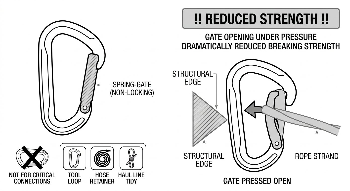
A non-locking connector — a plain spring gate, snap gate or wire gate — has nothing holding the gate shut but its own spring. Any pressure from rope, webbing, a harness loop or a structural edge can push it open, and a connector with an open gate is a fraction of its rated strength.
Non-locking connectors have no place at a critical connection: not on the harness attachment point, not at the anchor, not on a descender, rope grab or back-up device, and not on any lanyard that arrests or restrains a person. Their legitimate use is limited to non-critical, constantly attended tasks — racking tools on a gear loop, retaining a hose or cable, holding a haul line tidy — where failure of the connector puts no one at risk of a fall.
The practical rule is unambiguous: if a person’s weight, or the arrest of a fall, can ever reach that connector, it must lock.
Loading geometry beats locking type
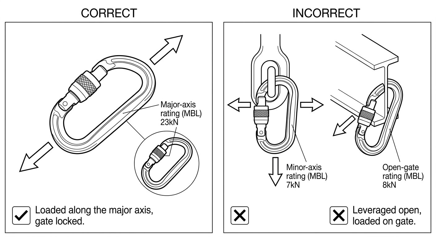
A three-stage auto-lock loaded badly is weaker than a screw-lock loaded well. Connectors are rated along their major axis — the long axis, spine to gate, with the gate closed and locked — and every connector carries additional, much lower ratings for minor-axis and open-gate loading, marked on the body. Those two conditions are among the most common real rigging errors on site.
Minor-axis (cross) loading happens when the connector is forced to take load across its width: caught in a narrow anchor eye, jammed in a bracket, twisted by a wide sling, or hung up on the edge of a rigging plate. Gate loading happens when the gate itself, or the sleeve, presses against a beam flange, a rung, a bolt head or the edge of an opening, so the frame is being levered open rather than pulled straight.
Three checks prevent nearly all of it:
- Check the alignment. The load path should run in a straight line down the connector’s long axis, spine loaded, before the system is weighted.
- Check what the connector can rotate into. Ask where it will sit once the rope moves and the technician’s position changes, not only where it sits now.
- Check the gate is clear. Nothing should be resting on the gate or the sleeve. Use a captive-eye or directional connector where the geometry keeps pulling it out of line.
Confirming a connector is actually locked
Visual confirmation is not enough on its own — a screw sleeve can look closed while a thread short, and an auto-lock sleeve can be held part-way by grit or ice. Confirm by touch:
- Push the gate inward with a thumb. It should not move at all.
- For screw-locks, turn the sleeve towards locked. It should already be seated, with no travel and no gap at the nose.
- For auto-locks, release the sleeve and let it return unaided, then test the gate. If the sleeve needs help to return, the mechanism needs cleaning or the connector needs withdrawing.
- Confirm the gate has closed fully into the nose — a fouled nose keyway or a bent gate will hold it slightly proud.
- Include the check in the buddy check, out loud, on every critical connection.
Choosing for the job
There is no single best mechanism, only a best fit for the connection:
- Harness attachment point and other set-and-forget connections: three-stage auto-lock, or a screw-lock that is checked at every buddy check.
- Working connections made and broken repeatedly during a descent: two-stage or three-stage auto-lock, chosen for one-handed operability with the gloves the crew actually wears.
- Anchors, slings and rigging left in place across a shift: screw-lock or screwlink, made up once and re-verified before each use.
- Confined space, tight anchor eyes, high snag risk: three-stage auto-lock, and prefer a captive-eye or directional shape to control alignment.
- Tools, hoses and tidying: non-locking connectors are fine — and should be visibly different in shape or colour so they are never confused with life-safety hardware.
Whichever mechanism the crew carries, standardising on it across a team pays off: people build a reliable muscle memory for one motion and one check, rather than guessing which sleeve is in their hand.
Next step: compare your current connector inventory against the connection points on your rescue and work plans, and confirm each connector’s marked class and standard (EN 362, with EN 12275 items identified separately) matches the role it is filling. Anything with a sluggish sleeve, a gate that does not seat cleanly, or wear at the nose should come out of service before the next shift, not after it.
Frequently asked questions
Which locking type is required at a critical connection?
Any connection that can take a person's weight or arrest a fall — harness attachment, anchor, descender, rope grab, back-up device — must use a locking connector. Screw-lock, two-stage auto-lock and three-stage auto-lock are all acceptable in principle; the choice depends on how often the connection is made and broken and how much snag risk the location presents. Non-locking connectors are never acceptable at these points.
Which standard applies to connectors in fall protection?
EN 362 governs connectors for personal fall-protection equipment and sets out the classes used for anchor, basic, multi-use, termination and screwlink connectors. EN 12275 governs connectors for mountaineering and is a different certification regime, even though the hardware may look similar. Where a system is specified to EN 362, use connectors marked to EN 362.
Is a three-stage auto-lock always better than a screw-lock?
Not automatically. A three-stage mechanism resists accidental opening better, but it is slower, more awkward with gloves, and more sensitive to grit and ice in the sleeve. A screw-lock that is properly wound down and re-checked at every buddy check is entirely appropriate for anchors and other semi-permanent connections.
How do I check that a connector is actually locked?
Confirm by touch rather than by eye. Push the gate inward with a thumb — it should not move at all — and for a screw-lock, turn the sleeve towards locked to confirm it is already seated with no gap at the nose. For auto-locks, let the sleeve return unaided and then test the gate; if it needs help to return, clean it or take it out of service.
Why does loading direction matter more than the locking mechanism?
Connectors are rated along their major axis with the gate closed and locked. Loaded across the minor axis, or with the gate pressed against an edge or held open, a connector is dramatically weaker than its marked major-axis rating. Cross loading and gate loading are among the most common rigging errors on site, and no locking mechanism compensates for them.
Are non-locking connectors ever acceptable on site?
Only for non-critical, constantly attended uses — racking tools, retaining a hose or cable, keeping a haul line tidy — where failure of the connector cannot put anyone at risk of a fall. Keep them visibly distinct in shape or colour so they are never mistaken for life-safety hardware.
Need this as a document you can issue? The template library gives you the risk assessments, permits and inspection logs in editable form — and employer plans cover a whole team with completion records.