
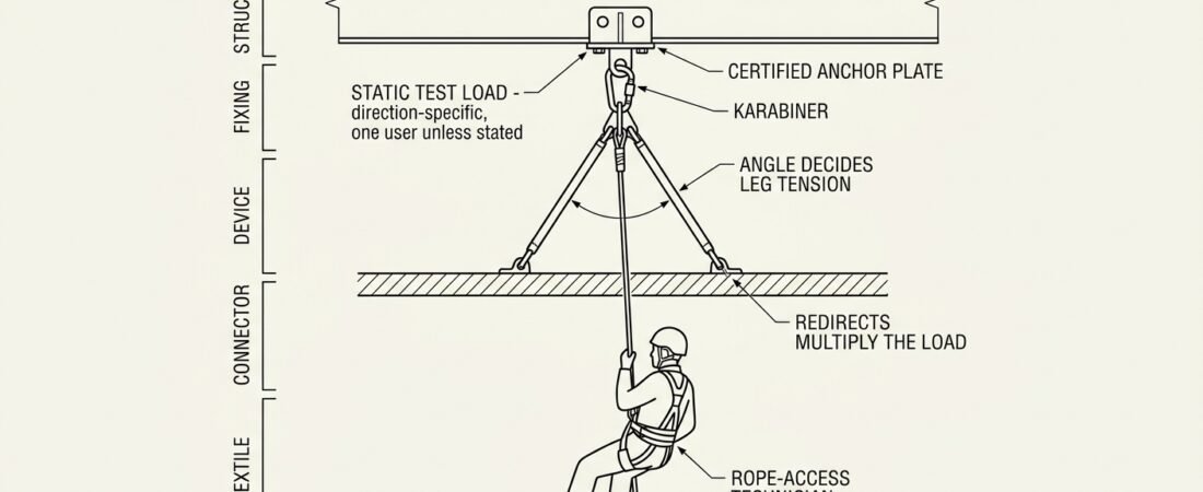
Every rope-access or confined-space system ends at an anchor, and the anchor is the one component a technician usually cannot inspect, test or replace on the day. Harnesses, connectors and descenders arrive with a marked rating and a known history; a structural beam, an eyebolt in concrete or a stainless post on a roof arrives with whatever the last contractor left behind. That is why anchor strength requirements are worth understanding as numbers rather than as slogans — not to memorise a figure, but to know which figure applies to the system being rigged, in which direction, and for how many people.
This note explains what the common anchor strength figures actually describe, how multipoint rigging and redirects change the load an anchor sees, and what can be checked in the field before clipping in.
Three different numbers, often confused
Most arguments about anchor strength on site come from mixing up three distinct quantities.
- Static test load / minimum static strength. A pass-or-fail value applied in a laboratory to a sample, in a defined direction, for a defined time. It proves the design does not fail at that load. It is not a load anyone is supposed to apply in service.
- Working load or rated load. What the manufacturer permits in use, usually derived from the static strength by dividing by a design factor. For personal fall protection this is often expressed as a number of users rather than in kilonewtons.
- Actual load in service. What the system will really deliver, which depends on the arrest force, the rigging geometry and the number of people on the anchor.
An anchor is adequate when the actual load, multiplied by an appropriate design factor, stays comfortably below the strength of the weakest element in the load path — including the structure itself. Reading the number stamped on a hardware component and stopping there is where most anchor errors begin. The same distinction applies further down the system; see harness attachment point strength ratings and what the numbers actually cover for the equivalent problem at the other end of the rope.
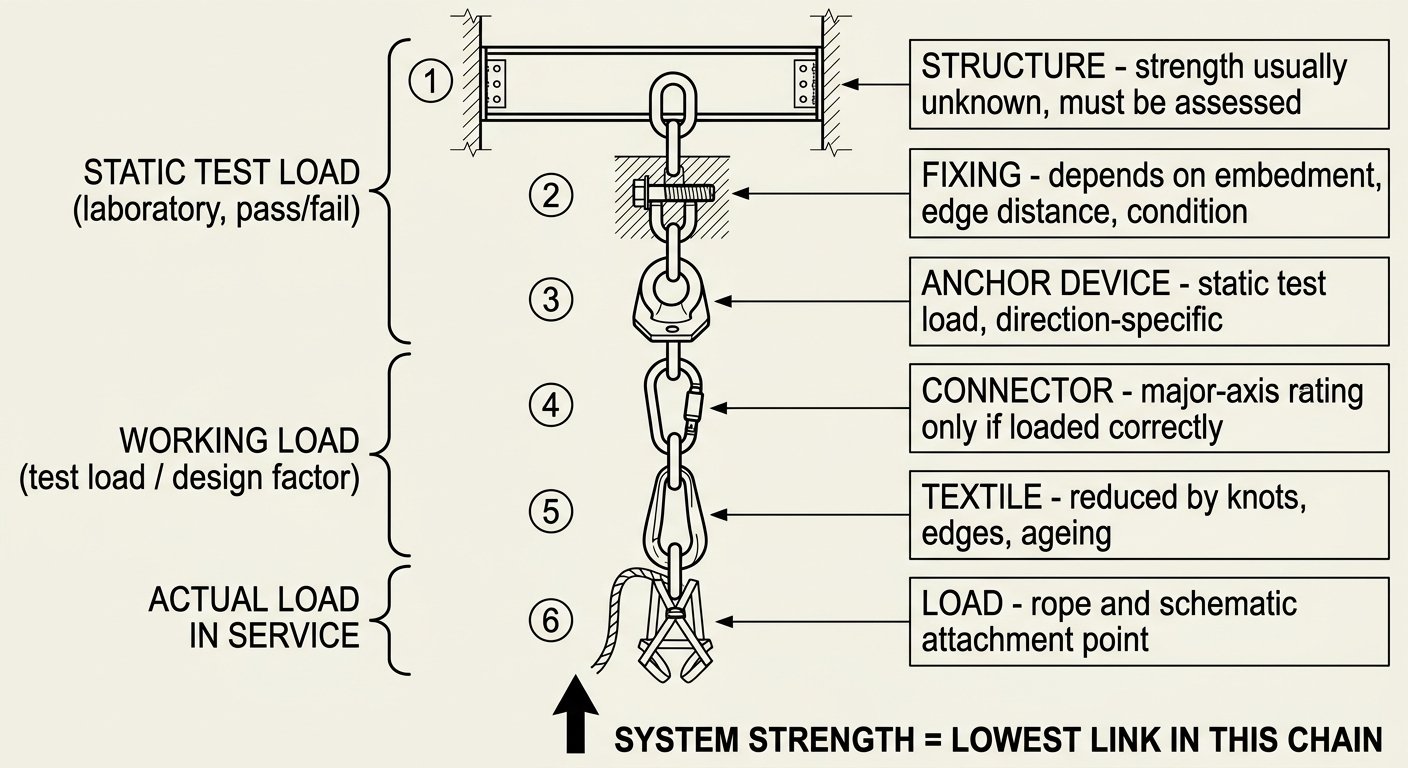
Anchor strength applies to the whole load path: the marked rating on the hardware is meaningless if the structure or fixing behind it is weaker.
What EN 795 requires of an anchor device
In Europe, anchor devices for personal fall protection are covered by EN 795, which classifies them by type:
- Type A — anchors fixed to the structure (eyebolts, plates, brackets).
- Type B — temporary transportable anchors (beam clamps, doorway/tripod-style anchors, textile slings).
- Type C — flexible horizontal anchor lines (wire or textile lifelines).
- Type D — rigid horizontal anchor rails.
- Type E — deadweight anchors for horizontal surfaces, relying on mass and friction.
The static strength test in EN 795 is commonly cited as 12 kN for metallic anchor devices and 18 kN for devices made of, or incorporating, non-metallic (textile) elements, applied in the intended direction of loading. The higher figure for textiles reflects their sensitivity to abrasion, edges, ageing and knotting. EN 795 also includes a dynamic performance test using a falling mass, because a static proof load alone tells you nothing about how a deforming or sliding device behaves during an arrest.
Two consequences matter in the field:
- EN 795 certification is normally for one person. Where an anchor device is intended for simultaneous use by more than one person, the additional test requirements in the associated technical specification (CEN/TS 16415) apply. An anchor marked for a single user is not automatically fit for two technicians plus a rescue load.
- The certificate covers the device, not the structure. A Type B beam clamp tested to 12 kN is worthless on a corroded purlin. A Type A eyebolt is only as strong as its fixing and its substrate.
The OSHA and ANSI figures, and why they look so different
Anyone working to North American rules, or reading equipment literature written for both markets, meets a very different-looking number. Under OSHA construction rules, anchorages used for personal fall arrest must support at least 5,000 lbf (about 22.2 kN) per attached worker, or alternatively be designed, installed and used as part of a complete system that maintains a safety factor of at least two, under the supervision of a qualified person. Anchorages for work positioning are held to a lower figure, commonly cited as 3,000 lbf. ANSI/ASSP Z359 follows the same logic, distinguishing a non-certified anchorage (the blanket 5,000 lbf figure) from a certified anchorage designed by a qualified person to a stated multiple of the maximum arrest force.
The gap between 12 kN and 22.2 kN is not a disagreement about physics. The European figure is a component test load applied to certified hardware whose behaviour in a fall is separately verified; the American figure is a deliberately conservative blanket value intended to cover anchorages chosen on site by people who are not running calculations. Both frameworks arrive at the same practical position: either the anchor is an engineered, verified item, or it is generously oversized.
Rope-access codes of practice typically specify their own minimum per-anchor strength for a single-person system, commonly in the region of 12–15 kN in the direction of loading, with redundancy requirements on top. Which figure governs a given job depends on jurisdiction, client specification and the applicable code of practice — that determination belongs at the planning stage, alongside the other decisions covered in general principles for work at height and the order of decisions before you rig.
Strength is directional
An anchor is rated for a direction, not for space in general. An eyebolt designed for axial pull can be substantially weaker in shear or in a pull that levers against the plate. A beam clamp installed for a downward pull may unload or rotate under a sideways pull. A structural anchor tested along the flange can behave very differently across it.
Two habits follow. First, the anchor should be positioned so that the resultant of the working line and any expected swing stays inside the direction the device is approved for. Second, where the direction of pull will change during the task — a traverse, a descent that swings under a canopy, a hauling system that reverses — the anchor should be assessed for the worst-case direction, not the one that exists at the moment of rigging.
The connector at the anchor is part of this: a karabiner cross-loaded against a wide plate or levered over an edge loses a large fraction of its major-axis strength. Choosing connectors for anchor rigging — shape, closure and correct loading covers that interface in detail.
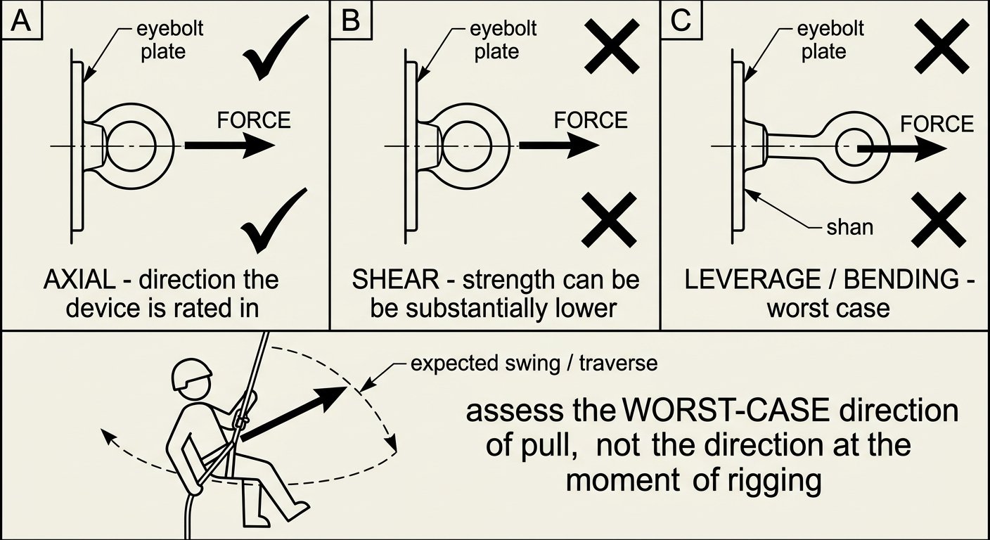
Anchors are rated in a direction: axial pull, shear and levered loading are not equivalent, and swing or traverse can change which one applies.
Multipoint anchors: the angle decides the load
Sharing a load between two points does not automatically halve it. The tension in each leg depends on the internal angle at the load, and it rises quickly as that angle opens:
- At a narrow internal angle (roughly 0–30°), each leg carries a little over half the load — close to the ideal split.
- At about 90°, each leg carries roughly 70% of the load.
- At about 120°, each leg carries approximately the full load — the sharing benefit has disappeared entirely.
- Beyond 120° the tension in each leg exceeds the applied load, and continues to climb steeply.
This is why a wide, flat two-bolt anchor rigged with a short sling can be worse than a single good point: both legs are loaded harder than the technician weighs, and neither point has any reserve for the shock of the other one failing. Keeping the internal angle small is usually a matter of extending the legs, not moving the points.
A second distinction matters where redundancy is the goal. A load-sharing (fixed) rig splits the load in a chosen ratio and holds it; if one point fails, the load transfers with a shock. A load-distributing (self-adjusting) rig follows changes in direction of pull but usually introduces extension — the drop that occurs if one point fails. Neither is universally correct; what matters is that the surviving point, and the connectors and textiles in that path, can absorb the transfer.
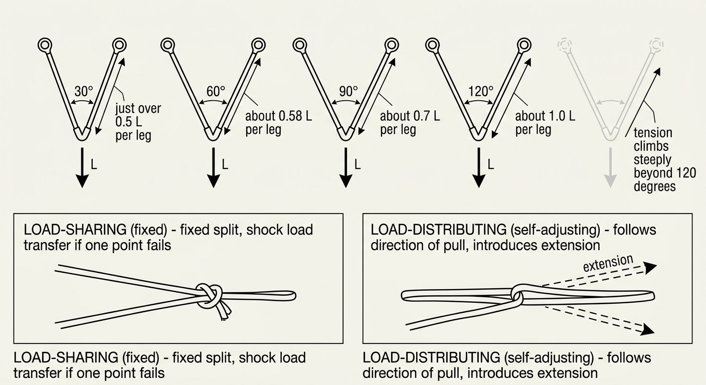
Sharing a load between two points only helps while the internal angle stays narrow: at about 120 degrees each leg carries roughly the full load.
Redirects, deviations and horizontal lines multiply the load
Some anchors carry more than the load hanging from them.
Redirects and deviations. An anchor that turns a loaded rope sees the resultant of the two rope tensions. A small deviation — pulling the rope a few degrees off line to clear an edge or a window reveal — produces only a small force on the deviation point. A rope turned through a full 180° over a pulley or bar loads that anchor with roughly twice the line tension (more, once pulley friction is included). Mid-range angles fall between the two. A deviation point chosen for convenience at ground level can become a highly loaded anchor once the rope geometry closes up during the descent. The same reasoning drives pulley and bollard selection — see pulley efficiency and what the numbers mean.
Hauling systems. A mechanical advantage system multiplies the force applied by the haul team into the load line, and the anchor holding the system carries the sum of the strands acting on it. This is the situation in which anchors most often see forces well above a single person’s weight, and where a static rigging calculation is genuinely needed rather than a rule of thumb.
Flexible horizontal lifelines (EN 795 Type C). The tension in a sagging line, and therefore the force at each end anchor, is amplified by the shallowness of the sag angle. A tightly tensioned line with a small sag angle can develop end loads several times the load applied at mid-span. These systems are engineered as a whole: span length, permitted sag, number of users, energy absorber at the end anchor and required anchor strength are all fixed by the manufacturer’s design documentation. Substituting a component, extending a span or adding a user changes the anchor requirement, and the only valid source for the revised figure is the system manufacturer or a structural engineer.
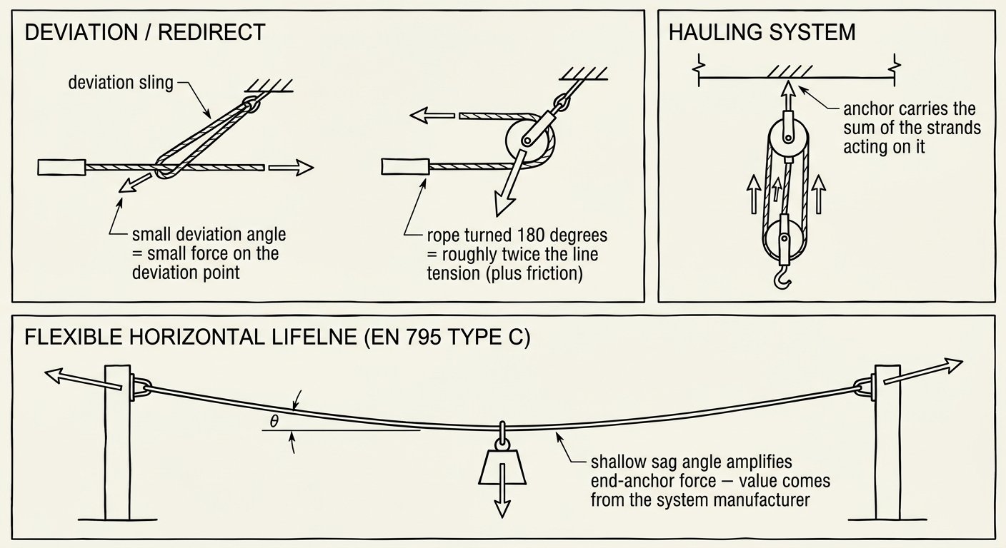
Redirects, haul systems and tensioned horizontal lines all load their anchors with more than the weight hanging from the rope.
The load the system actually delivers
Working from the other direction — what will the anchor really see? — is often more informative than reciting minimum strengths.
- Rope access on a tensioned, correctly rigged line generates modest static loads: body weight plus tools, plus dynamic increments from bouncing, jamming or a short slip onto a rope grab. Loads remain a small fraction of the anchor’s rated strength in normal operation.
- Fall arrest with an energy absorber is limited by design so that the force on the person stays within the limit set by the applicable standard, and the force transmitted to the anchor is of the same order — typically well under the anchor’s test load, provided the absorber can deploy fully. Clearance and deployment interact directly; see energy absorber deployment lengths and how they change your clearance.
- Fall arrest without an absorber — or with a factor-2 fall onto a short, stiff link — produces far higher peak forces, which is precisely the scenario the conservative anchor figures exist to cover.
- Rescue loads approximately double the mass and add a second person’s dynamic contribution. An anchor chosen for one technician needs re-examination before it becomes the anchor for a two-person lower or haul.
The structure is usually the weakest link
Certified hardware fails rarely; the thing it is bolted to fails more often. Before an anchor is used, the structure behind it needs an assessment appropriate to what it is:
- Installed anchors (Type A): is there documentation — installation record, design calculation, proof-test certificate, periodic inspection record? Is the substrate sound, uncracked, free of spalling and corrosion? Is the fixing the one specified for that substrate?
- Structural steel: is the member part of the primary structure or a light secondary element? Is the connection at each end capable of the pull, and is the pull in a sensible direction relative to the member?
- Concrete: post-installed anchors depend on hole preparation, embedment, edge distance, spacing and cure. Where the installation history is unknown, on-site proof testing by a competent person is the only way to establish anything.
- Deadweight and friction anchors (Type E): performance depends on mass, surface material, contamination and slope. Ice, dust, wet membrane or a slight fall in the roof can change behaviour substantially. These are engineered products, used strictly within the manufacturer’s surface and slope limits, and are not a good choice where lateral loads are expected.
- Improvised structural anchors: handrails, ladder stiles, small-bore pipework, cable trays, ductwork and lightning conductors are frequent offenders. Handrails in particular are commonly designed for a modest lateral push, not for arresting a fall.
Textile anchor slings deserve their own check. Their rated strength assumes the sling is undamaged, correctly configured and not loaded over a sharp edge or through a knot. Edge loading and knots reduce strength materially, and ultraviolet, chemical and abrasion damage accumulate invisibly — which is why service life and retirement criteria for textiles apply to anchor slings just as they do to lanyards.
A short field sequence before you commit
- Identify what the anchor is. A certified anchor device with markings and records, or a structural feature judged on site? The two are assessed differently.
- Establish the governing requirement. Which standard or code of practice applies to this job, and for how many people simultaneously.
- Determine the direction of pull for the whole task, including swing, traverse and the rescue case — then confirm the anchor is rated in that direction.
- Work out what the anchor will actually carry, including redirect and mechanical-advantage multiplication, not just the mass of the person.
- Check the load path element by element: structure, fixing, anchor device, connector, sling or rope. The system strength is the lowest figure in that chain, in the actual loading configuration.
- Provide redundancy where the assessment is uncertain, keeping the internal angle narrow, and confirm the surviving point could take the transfer.
- Record what was used, so the next team knows what was assessed and on what basis.
Takeaway
Anchor strength requirements are not one number. The 12 kN and 18 kN static test values in EN 795 describe what a certified device survives in a laboratory; the 22.2 kN blanket figure in North American rules describes an intentionally conservative substitute for calculation; the per-anchor minimums in rope-access codes describe the redundant systems those codes assume. In every framework, the requirement is stated in a direction of loading, for a defined number of users, and it applies to the whole load path — structure and fixing included. Geometry then decides how much of the applied load each point actually feels: keep multipoint angles narrow, treat redirects and haul systems as amplifiers, and re-assess the anchor before it becomes a rescue anchor.
Related technique notes on rigging, connectors and rope selection are collected in the rope access and confined space technique notes.
Frequently asked questions
Is the 12 kN figure in EN 795 a working load?
No. It is a static strength test value applied to a sample in the laboratory, in the intended direction of loading, to demonstrate that the design does not fail. Devices incorporating non-metallic or textile elements are tested to a higher value, commonly cited as 18 kN. Permitted use in service is defined by the manufacturer’s instructions, including the number of users, not by the test figure.
Why does OSHA require about 22.2 kN when EN 795 tests to 12 kN?
The two figures describe different things. The European value is a component test load applied to certified hardware whose dynamic behaviour is separately verified, while the North American 5,000 lbf (about 22.2 kN) value is a deliberately conservative blanket figure for anchorages selected on site without calculation. OSHA also allows the alternative of an engineered anchorage maintaining a safety factor of at least two under the supervision of a qualified person.
Can two technicians use the same anchor at the same time?
Only if the anchor is rated for it. EN 795 certification is normally for a single user, with additional requirements applying where simultaneous use by more than one person is intended. The same applies to rescue: an anchor accepted for one technician should be re-assessed before it carries a two-person lower or haul.
Does splitting the load across two anchors halve the load on each?
Not in general. The tension in each leg depends on the internal angle at the load point: it is close to half only at narrow angles, rises to roughly 70% of the load at about 90 degrees, and reaches approximately the full load at about 120 degrees. Keeping the angle narrow, usually by extending the legs, is what makes multipoint rigging worthwhile.
How much force does a rope redirect put on its anchor?
It depends on the change of direction. A shallow deviation that pulls the rope a few degrees off line produces only a small force on that point, while a rope turned through a full 180 degrees loads its anchor with roughly twice the line tension, plus the effect of friction. Deviation geometry often closes up during a descent, so the worst case should be assessed at the planning stage.
Can a handrail be used as an anchor?
Generally not without engineering verification. Handrails are commonly designed for a modest lateral push by a person, not for the forces generated in arresting a fall or in a hauling system. The same caution applies to ladder stiles, small-bore pipework, cable trays, ductwork and lightning conductors.