
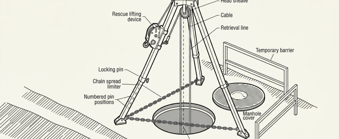
A tripod over a manhole is the anchor that everything else in a vertical confined space entry hangs from: the access line, the fall-arrest or retrieval line, and in many cases the rescue lifting device that will be used if the entrant has to be brought out unconscious. If the legs are unevenly extended, the spread limiter is slack, or the head sits off to one side of the opening, the whole system inherits that error. Most tripod failures on site are not equipment failures — they are geometry and footing errors made in the two minutes it took to stand the frame up.
This note covers the setup itself: preparing the ground around the opening, extending and pinning the legs, centring the head, and rigging lines through the head without side-loading anything. It assumes the entry permit, isolation and gas testing are already handled as a separate process.
What a tripod is for, and what it is not
A manhole tripod is a portable temporary anchor device — the category covered in Europe by EN 795 Type B — usually supplied with a top bracket or head plate carrying two or more anchor eyes, plus leg brackets for mounting a winch or a retractable device. Rescue lifting devices attached to it are typically assessed to EN 1496, and fall-arrest components to their own standards. The relevant point on site is that a tripod is rated as a personal anchor, not as a lifting appliance: it is not there to lift pumps, grating, silt buckets or tooling. Using it as a crane loads the head and legs in directions the frame was never assessed for, and it is one of the more common ways tripods get quietly damaged before the day they are needed.
Capacity is normally stated for one person on each line, with the manufacturer’s instructions defining whether both anchor points may be loaded simultaneously and whether the rescue device may be used for raising a second person. Those limits vary between models, so the marking on the head and the manual govern — not the assumption carried over from a different tripod. The same logic applies to the anchor itself as to any other: see anchor strength requirements and direction of pull for why the stated rating only holds for the loading directions the device was tested in.
Before the tripod goes up
Sequence matters here, because a tripod standing over an open manhole changes what you can still do around the opening.
- Permit, isolation and lock-out complete. The paperwork and the physical isolations come first; see the confined space entry permit sequence for the order those steps are normally taken in.
- Atmosphere tested from outside. Remote sampling through the open cover, top to bottom, before anyone leans over it — the method is set out in atmospheric testing before entry. Continuous monitoring then runs throughout.
- Traffic management and exclusion zone in place. Manholes are usually in carriageways, yards or plant walkways. The tripod legs extend the footprint well beyond the cover, and a vehicle clipping a leg is a realistic hazard.
- Cover moved clear, not just slid aside. A cover left half over the opening becomes a trip hazard inside the working area and can foul a leg or a descending line.
- Opening guarded or attended. Between removing the cover and rigging the tripod there is a period where an unprotected hole exists; a temporary barrier or a person stationed there covers it.
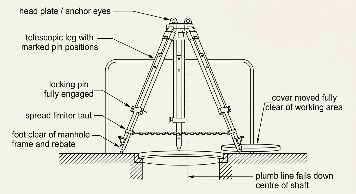
The reference geometry: legs pinned at matching positions, limiter taut, and a plumb line from the loaded anchor eye dropping down the centre of the shaft.
Assessing the footing
The tripod resolves the entrant’s weight into three compression loads along the legs, plus an outward thrust at each foot that the spread limiter has to restrain. Both parts of that need a surface that will not move.
- Flat and firm. Concrete, asphalt, steel plate or compacted hardstanding. Soft verge, loose gravel, mud, or the shoulder of a road trench will let one foot sink and take the frame out of plumb under load.
- Level, or made level. Where the ground falls away, legs are extended differently to bring the head plumb — that is normal and acceptable within the marked leg positions, provided the spread stays within the manufacturer’s range. What is not acceptable is a head that leans, because the load line then no longer runs down the centre of the opening.
- Correct feet for the surface. Most tripods offer rubber pads for hard surfaces and spikes or pointed feet for soil. Rubber pads on wet steel or ice give very little; spikes on smooth concrete give none at all.
- Not straddling the void. No foot should land on the manhole frame lip, on a loose slab, on a cover that could shift, or inside the rebate the cover sits in.
- Debris cleared. Silt, grit and small tools underfoot both reduce friction and end up down the shaft onto the entrant.
Where the surroundings genuinely cannot provide a stable footing — a grated platform, a sloping bund wall, a chamber roof — the answer is usually a different anchor arrangement rather than an improvised one, for example a davit socket or a structural anchor with a rigged deviation.
Extending and pinning the legs
Work through the legs one at a time, then check them against each other.
- Stand the frame roughly in position, legs closed. Then walk the feet outwards in stages rather than dropping the whole assembly open in one movement.
- Extend each leg to a marked hole position and engage the locking pin fully. The pin should pass right through and its retaining clip, ball detent or spring lock should be visibly captured. A pin resting in a hole under gravity alone is not engaged.
- Match the hole positions across all three legs on level ground — most tripods number or mark them for exactly this reason. On sloping ground, set them deliberately unequal to bring the head level, and confirm afterwards rather than assuming.
- Set the leg spread with the limiter, not by eye. The chain, strap or wire limiter between the feet defines the permitted spread. It should be taut, at equal length on each side, and connected at its designed points. Slack in the limiter is the mechanism by which a tripod turns into a set of splayed legs.
- Check the head height against the task. High enough that the entrant clears the rim and the rescue device has usable travel; low enough that the attendant can reach the head fittings and the device controls without climbing on the legs. Higher is not automatically better — a taller frame with the same footprint is less stable, and manufacturers usually restrict the highest positions accordingly.
Once the frame is standing, load-check it by hand: lean weight onto the head, watch for a foot lifting or sliding, and re-seat anything that moves.
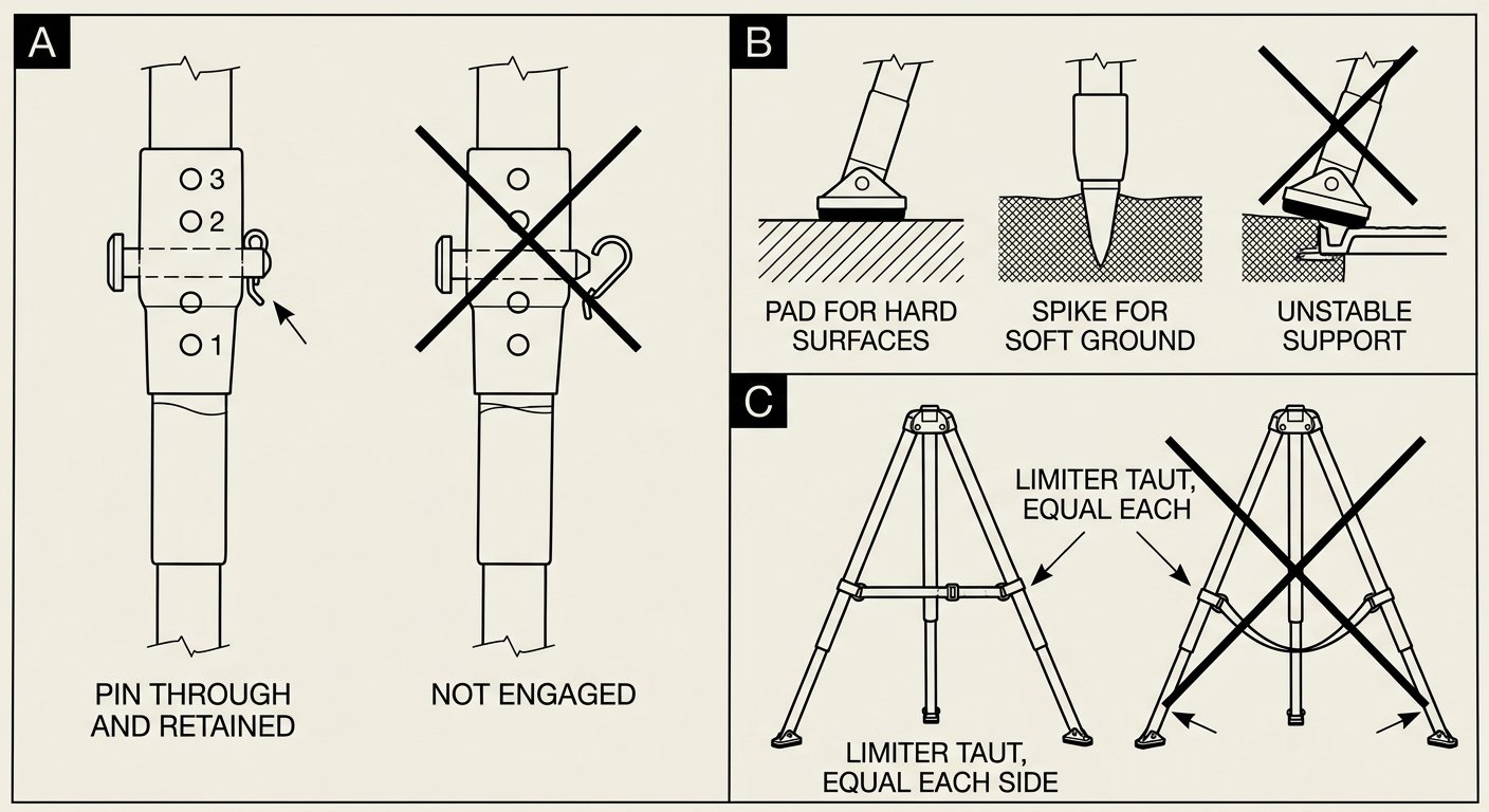
Leg detail: pins fully engaged and retained, feet matched to the surface, and a spread limiter that is taut rather than sagging.
Centring the head over the opening
The head should sit so that a line dropped from the loaded anchor eye falls down the middle of the shaft. The practical check is simple: hang the access line with a small weight and see where it enters the opening. If it touches the rim, the frame is off-centre, and three problems follow at once.
- The line runs over the manhole frame or the concrete rebate — abrasion on a loaded rope, at the one point you cannot see from below.
- The entrant swings sideways on load and on unload, into the shaft wall or the ladder.
- A rescue haul pulls the load against the rim instead of straight up, adding friction exactly when the system needs the least.
Where a shaft is offset, benched or has an eccentric opening, centre the head on the line path rather than on the cover, and fit edge protection — a rim roller, a sleeve or a padded protector — anywhere a loaded line still contacts a hard edge.
Rigging the lines through the head
A vertical entry normally runs two independent systems from the tripod head: a working or access line the entrant descends and ascends on, and a fall-arrest or retrieval line that is available for recovery. Under 29 CFR 1910.146, US practice requires a retrieval system with a mechanical device readily available for vertical permit spaces more than 5 feet deep, which in most manhole work means the rescue winch is rigged before the entrant leaves the surface, not fetched afterwards.
Points to get right at the head:
- Use separate anchor eyes for separate systems where the head provides them, and follow the manufacturer’s designation of which eye takes which device. Some heads reserve a specific eye for the rescue lifting device.
- Run lines through the head pulleys or sheaves so they sit in the groove and pull in the plane the sheave is designed for. A cable that leaves a sheave at an angle chafes the flange and, on a winch drum, spools unevenly.
- Do not cross the two lines in the head or down the shaft. Crossed lines twist together on descent, jam a rope grab and complicate any rescue.
- Mount the winch or retractable device on the designated leg bracket only, with its cable led up to the correct head sheave. Bolting a device to a random point on a leg loads that tube in bending.
- Load connectors along their major axis, gates closed and locked, with nothing bearing on the gate. The same compatibility checks apply here as anywhere else in the system — see checking connector compatibility before you clip in.
- Keep spare cable and rope tails managed in a bag or coiled off the ground, not looped where a foot or a vehicle can catch them.
On the person side, the attachment used for retrieval matters as much as the anchor. Suspension and lifting from a single dorsal point drags an unconscious casualty out head-down-adjacent to the wall; a harness with a rescue attachment arrangement to EN 1497, or a dedicated rescue harness worn with the working harness, keeps the casualty upright and clear. Whichever is used, it has to be selected and fitted before entry, not decided during a callout.
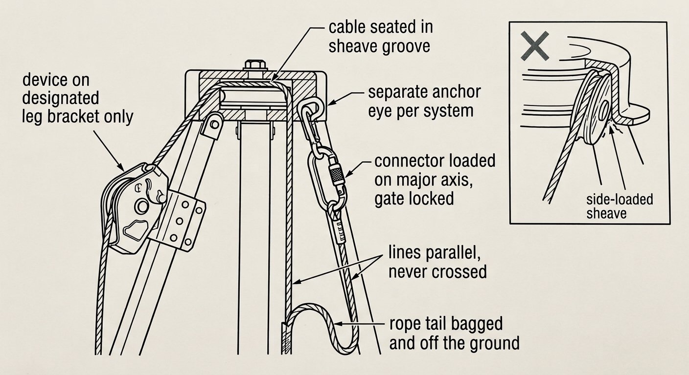
Head rigging: one system per anchor eye, cable seated in the sheave groove, lines parallel and uncrossed down the shaft.
Pre-entry checks on the erected tripod
A short, fixed sequence before the entrant clips in:
- All three locking pins through and retained; hole positions as intended.
- Spread limiter taut, symmetrical, connected at both designed points.
- Feet correct for the surface, all three in full contact, none on the manhole frame or a loose slab.
- Head level; plumb check confirms the line drops clear of the rim.
- Winch or rescue device mounted on its bracket, fasteners tight, cable seated in the sheave, drum spooling evenly.
- Device function-tested through raise and lower, and any clutch or rescue-mode changeover operated and understood before it is needed.
- Connectors locked and correctly oriented; edge protection fitted anywhere a line touches.
- Rescue plan confirmed with the attendant, and the rescue equipment laid out — not still in the van. The selection of a rescue kit for the task should already reflect the shaft depth and the recovery method.
While the entry is live
The tripod is not adjusted with someone on the line. Leg positions, head height and frame location are fixed before entry and stay fixed until the entrant is out. The attendant stays at the opening, keeps the retrieval line managed so it neither goes slack in coils nor drags the entrant, and does not use the legs as a ladder or a rest for tools. Nobody stands inside the footprint in a way that would foul the lines during a hoist.
If the entrant needs to move laterally in a chamber, the retrieval line stays connected and is managed by the attendant rather than unclipped for convenience — the point at which a retrieval line is disconnected is the point at which the mechanical recovery capability disappears.
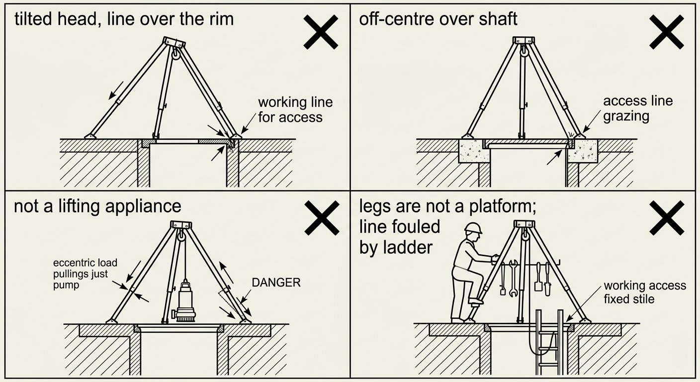
The four errors that recur most often: a tilted head, an off-centre frame, lifting plant with the tripod, and lines fouled by the ladder.
Recurring setup errors
- Unequal leg extension on level ground, producing a tilted head and an off-centre load line.
- Slack or disconnected spread limiter — the legs then rely on friction alone to resist splaying.
- Head set at maximum height by default without checking the manufacturer’s restriction for that leg spread.
- Frame centred on the cover rather than on the shaft, so the line grazes the rim throughout the entry.
- Rescue device fitted to the wrong bracket or the wrong head eye, or cable running off the sheave groove.
- Using the tripod to lift plant or grating, then leaving it in service with no inspection.
- Ladder and lines competing for the same space in the shaft, with the access line running behind the stiles.
- No edge protection where a loaded rope crosses cast iron or concrete.
Takedown
Remove load from the lines, then de-rig in reverse: lines off the head, device off the bracket, legs walked in before the limiter is disconnected — not the other way round, which lets the legs splay as soon as tension goes. Inspect the frame as it comes down: bent leg tubes, sloppy pin holes, damaged sheaves, kinked or birdcaged winch cable, and any foot pad worn to the metal. Record anything found, replace the cover, and confirm the opening is closed before the exclusion zone comes down.
For related technique notes on rigging, anchors, harness selection and rescue in vertical confined spaces, see the rope access and confined space technique notes.
Frequently asked questions
How do I know the tripod head is centred over the manhole?
Hang the access line from the loaded anchor eye with a small weight and watch where it enters the opening. If it touches the cast-iron frame or the concrete rebate, the frame is off-centre and needs repositioning. Where the shaft is offset or benched, centre the head on the intended line path rather than on the cover, and fit edge protection anywhere a loaded line still contacts a hard edge.
Can a manhole tripod be used to lift equipment out of the chamber?
No. A tripod of this type is a portable anchor device for personal fall protection and rescue, not a lifting appliance, and its rating applies to the loading directions it was assessed in. Hoisting pumps, grating or silt buckets loads the head and legs eccentrically and can damage the frame without visible signs. Use separate lifting equipment for materials.
Do the legs have to be extended to the same length?
On level ground, yes — matching the marked hole positions on all three legs keeps the head level and the load line vertical. On sloping ground the legs are deliberately set unequal to bring the head level, provided the leg spread stays within the manufacturer’s permitted range and the spread limiter remains taut.
What does the chain or strap between the feet actually do?
It is the spread limiter, and it restrains the outward thrust at each foot that the entrant’s weight generates. If it is slack, disconnected or unequal, the frame relies on friction between the feet and the ground to stop the legs splaying. It should be taut, symmetrical, and connected only at its designed attachment points.
Does the retrieval winch have to be rigged before entry, or can it be fetched if needed?
It is rigged before the entrant leaves the surface. Under 29 CFR 1910.146, a retrieval system with a mechanical device must be readily available for vertical permit spaces more than 5 feet deep, and the practical reason is the same everywhere: recovery time in a confined space is measured in minutes. Function-test the raise, lower and any rescue-mode changeover before entry rather than during an incident.
Can the tripod be repositioned while someone is in the shaft?
No. Leg positions, head height and frame location are set before entry and remain fixed until the entrant is out. Adjusting a loaded frame removes the load path assumption the setup was checked against and can shift the feet. If the position turns out to be wrong, the entrant comes out before anything is changed.