
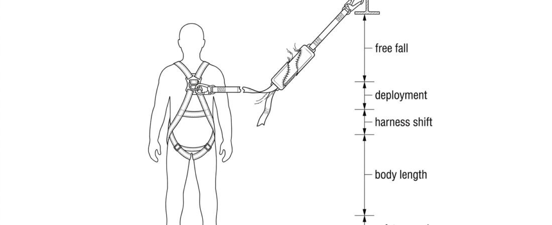
An energy absorber does its job by getting longer. That is the whole mechanism: stitching tears, webbing pays out, and the arrest force on the body is held down to a survivable level. The consequence for anyone planning work at height is that the lanyard length printed on the label is not the space the system needs below the anchor. A 2 m absorbing lanyard typically needs something in the order of 6 m of clear fall space beneath the anchor point before a fall is actually arrested clear of the ground or the next obstruction. Deployment length is the term for the extra webbing that pays out during arrest, and it is the figure most often left out of a clearance calculation on site.
What “deployment length” actually measures
Deployment length is the increase in length of the absorber (and, in some data sheets, of the whole lanyard assembly) between its packed condition and its condition after arresting a fall. In a torn-webbing absorber, folded webbing is held in a pack by rows of sacrificial stitching; the load required to break that stitching is what limits the arrest force, and the length of webbing released is what limits the deceleration distance. Tearing-strip and rip-stitch designs differ in detail, but the principle is identical: the absorber trades length for force.
Two figures matter and they are not the same:
- Deployment (extension) — how much longer the absorber becomes. This is what you add to the fall distance.
- Total deployed length of the assembly — packed lanyard length plus deployment plus connectors. Some manufacturers publish this instead, which is why the same product can appear to have very different “deployment” values in different documents.
Read the data sheet carefully enough to know which of the two you are looking at. Adding a total deployed length to a free fall distance that already contains the lanyard length double-counts the lanyard; subtracting it out when the figure was only an increment leaves you short.
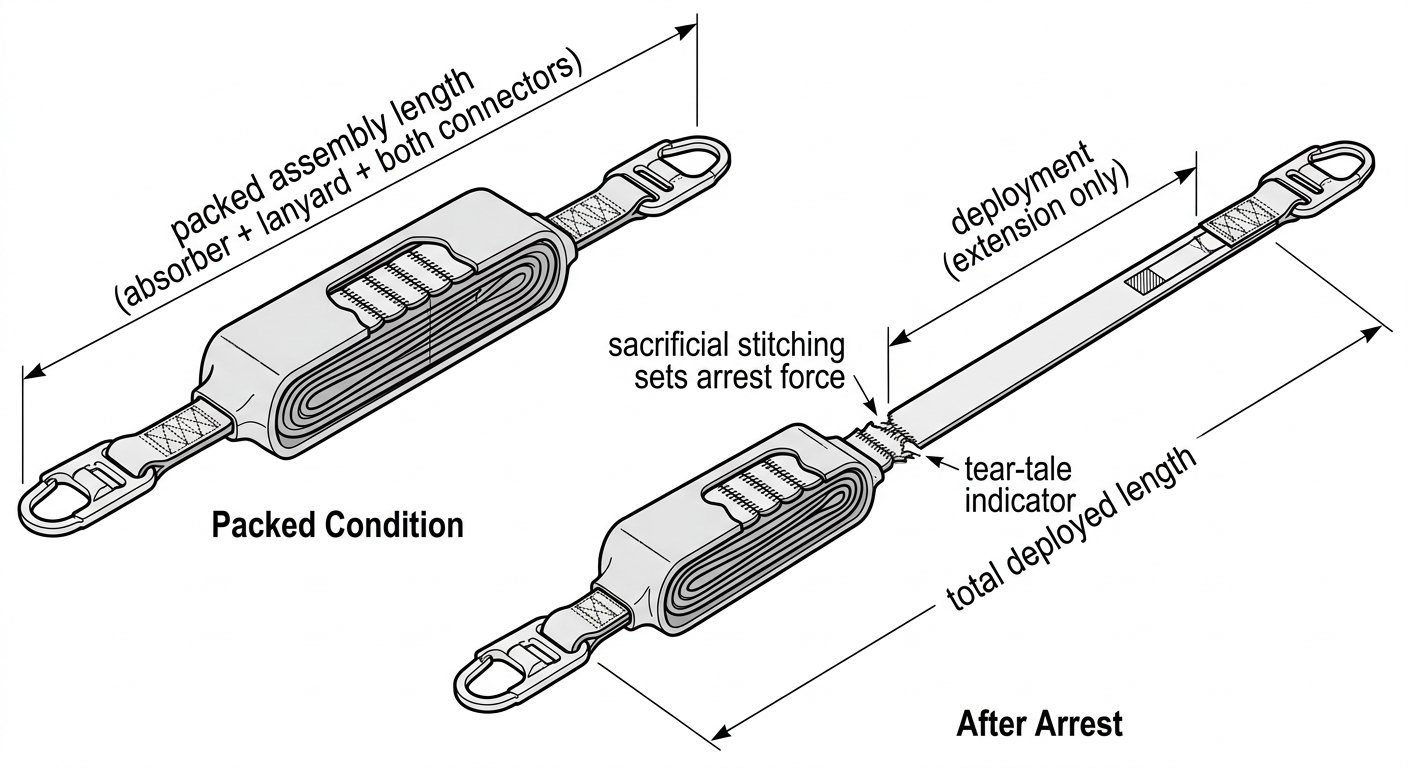
Deployment is the extension only; total deployed length includes the lanyard and connectors — data sheets may publish either.
What the standards cap
Under EN 355, an energy absorbing lanyard is tested as an assembly and two limits define its behaviour: the arrest force transmitted to the test mass must not exceed 6 kN, and the deployment measured in the test is capped — the commonly cited figure for maximum extension in the EN test is 1.75 m. The assembled lanyard, including the absorber, the lanyard itself and both connectors, must not exceed 2 m in total length. Those two numbers together are the reason a European absorbing lanyard is planned around roughly 4 m of fall before the body has stopped moving, before any allowance for harness stretch, body length or safety margin.
Absorbers built to ANSI/ASSP Z359.13 are described differently: the arrest force limit is higher (in the region of 8 kN, stated in the standard as 1,800 lbf) and deployment is capped at a shorter distance for a 6 ft free fall model, with a longer allowance for the 12 ft free fall variants. If you are working with equipment certified to both schemes, do not mix the figures — use the deployment stated for the certification the product is actually marked to, and check the markings on the components themselves rather than assuming.
One further point on the standards: the test is performed with a defined test mass. Historically that was 100 kg in the EN test; many current absorbers are marked for a user mass range that includes clothing, tools and equipment, and some are rated well above 100 kg. That rated range, not the bare body weight of the worker, is what the deployment figure applies to.
Why real deployment varies
The published deployment figure is a test result under controlled conditions, not a guarantee for every fall. In practice, deployment is influenced by:
- Total suspended mass. More energy to dissipate means more webbing pays out. A worker at the upper end of the marked mass range, carrying a tool belt, will typically deploy an absorber further than the test mass would.
- Fall factor. A fall onto an absorber anchored above the dorsal attachment generates less energy than the same lanyard anchored at foot level. Low fall factors often produce only partial deployment.
- Edge and redirect friction. Webbing dragged over a beam edge or through a redirect loses energy to friction, which can reduce deployment — but an edge also introduces cutting risk that no absorber addresses. Edge-tested lanyards exist specifically for that case.
- Contamination and condition. Grit, paint, resin or heat damage in the absorber pack can change how the stitching releases. This is a reason for retirement, not something to plan around.
Because of this variability, treat the published figure as the maximum you should design to, and never assume you will get less. Partial deployment is common and is not a sign that the absorber “worked less” — it means the fall was smaller. Either way the absorber is finished.
Adding deployment into a clearance stack
Clearance is a stack of distances measured from the anchor point downwards. A worked example for a 2 m absorbing lanyard, with the anchor at the level of the worker’s feet — the worst common case — assembles roughly as follows:
- Free fall — up to the full length of the assembled lanyard, so around 2 m in this geometry.
- Deployment — the absorber’s stated extension, up to about 1.75 m for an EN 355 lanyard.
- Harness stretch and dorsal attachment shift — a few tens of centimetres, as the webbing tightens and the D-ring rides up.
- Distance from the dorsal attachment to the feet — commonly taken as around 1.5 m for an average adult, and worth measuring for unusually tall workers.
- Safety margin — a clear residual distance below the feet at the lowest point of the arrest. One metre is a widely used figure; some manufacturers and national guidance specify more.
Added up, that is comfortably over 6 m of required clearance for a lanyard that measures 2 m in the bag. If the working level has less than that beneath it — a scaffold two lifts up, a vessel roof over internal steelwork, a mezzanine over plant — then an absorbing lanyard is the wrong choice and the system needs to change: a shorter absorber, a retractable type with a shorter arrest distance, a higher anchor, or a restraint arrangement that removes the fall potential altogether. The selection logic for that decision is set out in choosing an absorber for the clearance available.
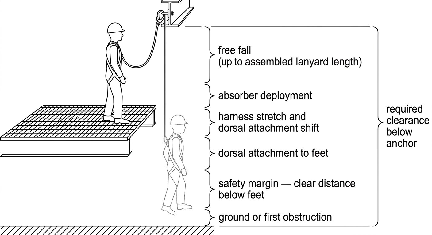
Deployment is only one segment of the clearance stack; every segment must be measured from the anchor downwards.
Anchor height changes the answer more than equipment choice does
Of everything in the stack, anchor position is the variable most often within the worker’s control on site and the one with the largest effect. Moving the anchor from foot level to above the dorsal attachment removes most or all of the free fall component, reduces the energy the absorber has to handle, and therefore reduces deployment as well. The same lanyard can require a very different clearance depending only on where it is clipped.
This is also where the geometry of the harness matters. Fall-arrest attachment points on an EN 361 full body harness — dorsal or sternal — are the only points that may take an absorbing lanyard; a work positioning belt attachment must never be used for fall arrest. Where the lanyard connects, and how well the harness is adjusted, both affect the dorsal shift allowance in the calculation, which is one more reason to work through correct harness adjustment and fit checks before the first clip-in rather than after.
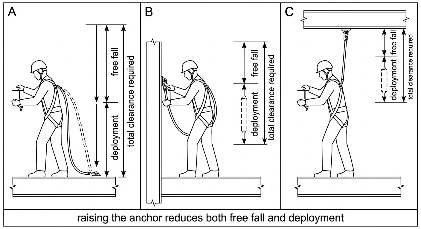
Anchor height is usually the variable with the largest effect on both deployment and total required clearance.
Do not lengthen the assembly
The 2 m limit under EN 355 applies to the complete assembly: absorber, lanyard, and the connectors at both ends. Adding an extra sling, a second connector, or a short strop at the anchor end to reach a better attachment adds free fall on top of a deployment figure that was validated for the shorter assembly. Every centimetre added at the top is a centimetre of extra free fall and a corresponding increase in required clearance — and it may push arrest forces beyond what the certified assembly was tested to produce.
The same applies to connectors substituted after purchase. Connector length, gate opening and locking type all belong to the assembly as certified; components should conform to EN 362 for fall protection connectors and should be compatible with the anchor being used. If the reach is genuinely insufficient, the answer is a different anchor or a different lanyard, not an extension.
With twin-leg (Y) lanyards, the published deployment applies to arrest on one loaded leg. Park the unused leg on a dedicated parking attachment on the harness, never back onto the absorber body or a lateral positioning ring, so that a fall does not load both legs into the anchor and shorten the effective absorber travel. Which configuration suits the task — single leg, twin leg, or retractable — is covered in the fall-arrest lanyard selection note.
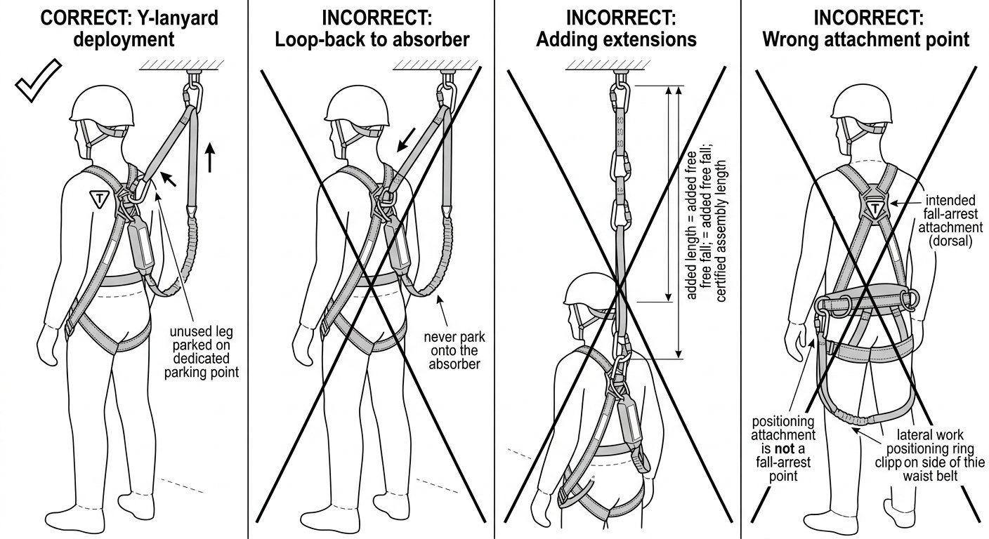
Lengthening the assembly or parking the spare leg on the absorber invalidates the deployment figure the clearance calculation relies on.
After a deployment, the absorber is finished
Any absorber that has arrested a fall is withdrawn from service and destroyed, regardless of how little webbing paid out. Most designs carry a visible indicator — an exposed tear-tale, a broken seal, a witness label inside the cover, or simply a pack that no longer sits flush — and any of these is grounds for immediate removal from service. Restitching, repacking or “just checking whether it still holds” are not options; there is no field method for restoring the tested arrest characteristics.
Pre-use inspection should include the absorber pack specifically, not just the lanyard webbing and connectors: check that the cover is intact and closed, that no stitching rows are visibly parted, that the pack has not been soaked, heat-glazed or contaminated, and that labelling remains legible. An absorber whose marking is unreadable cannot be shown to be within its rated mass range or its stated deployment, which makes the clearance calculation unverifiable.
Practical takeaway
Write the clearance calculation down before the job, using the deployment figure printed on the equipment you will actually take up — not a remembered number from a different product. Confirm what that figure represents (increment or total deployed length), add the free fall the anchor geometry permits, add harness shift, body length and margin, and compare the result to the real distance to the ground or the first obstruction. Where the numbers do not fit, change the anchor height or the equipment; deployment length is not negotiable once the fall has started.
For related technique notes on lanyards, harnesses and system geometry, see the rope access and confined space technique notes.
Frequently asked questions
How much clearance does a 2 m energy absorbing lanyard need?
Planned worst case, well over 6 m below the anchor when the anchor is at foot level. That figure comes from adding the free fall permitted by the lanyard length, the absorber’s stated deployment, harness stretch and dorsal attachment shift, the distance from the dorsal attachment to the feet, and a residual safety margin. Always run the calculation with the deployment figure printed on the specific equipment being used.
Does the deployment figure include the length of the lanyard itself?
It depends on the manufacturer. Some publish deployment as the extension only, others publish the total deployed length of the whole assembly including connectors. Check which one the data sheet gives before adding it to a free fall distance, otherwise you will either double-count the lanyard or leave it out entirely.
Will a heavier worker deploy the absorber further?
Generally yes, because there is more energy to dissipate. This is why absorbers are marked with a rated user mass range that is intended to include clothing, tools and carried equipment, not just body weight. Working outside that marked range means the published deployment and arrest force figures no longer apply.
Can an absorber be reused if it only deployed part way?
No. Any absorber that has arrested a fall is removed from service and destroyed, even if only a small amount of webbing paid out. Partial deployment simply means the fall was smaller; there is no field method for restoring the original arrest characteristics.
Can I add a sling at the anchor end to reach a better anchor point?
No. The maximum assembly length applies to the absorber, lanyard and both connectors together, and the deployment figure was validated for that assembly. Any added sling or extra connector increases free fall and can push arrest forces beyond what was tested. If the reach is short, change the anchor or the lanyard instead.
How do I tell whether an absorber has already deployed?
Look for the manufacturer’s deployment indicator: an exposed tear-tale, a broken seal or witness label, torn stitching rows visible through the cover, or a pack that no longer sits flush. Any of these signs, or illegible markings that prevent you from confirming the rated mass and deployment, is grounds for immediate withdrawal from service.