
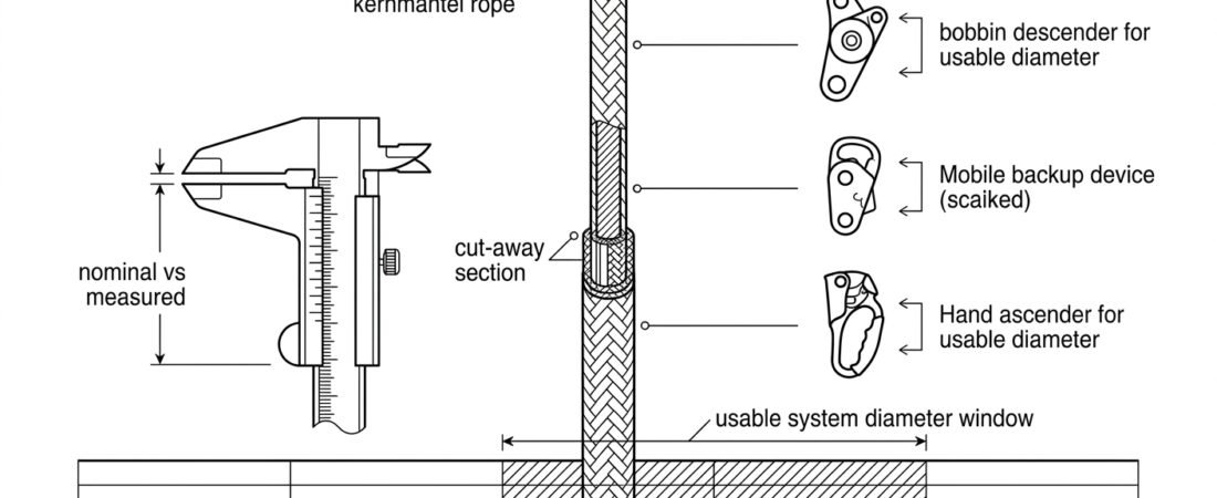
Rope diameter is a system compatibility decision before it is a strength decision. A low-stretch kernmantel rope that is half a millimetre outside the marked range of the descender or the backup device on the harness is the wrong rope for that system, regardless of how strong it is. Diameter also decides how the rope feels in the hand, how much heat the descender generates on a long drop, how much sheath can be lost to an edge before the core is at risk, and how much weight has to be carried up to the anchor. This note covers how to work out the diameter window for a given system, what genuinely changes as diameter goes up or down, and how to check a rope in the field before committing to it.
Where diameter sits in EN 1891
Low stretch kernmantel ropes for rope access, work positioning, rescue and caving are covered by EN 1891. The standard defines two types, A and B. Type A is the general working rope for industrial rope access; Type B is a lighter-duty rope with lower strength requirements and a smaller minimum diameter, intended for more restricted use and lower loads. Type A ropes start at 8.5 mm and Type B at 8 mm, with both types covered up to 16 mm.
The key point for a diameter decision is that diameter is not a usable proxy for performance across the two types. Minimum static strength for Type A is 22 kN and for Type B 18 kN, measured without terminations; with a knotted termination the required values are substantially lower, because the knot itself is the weak point. Elongation is limited to 5% between a 50 kg and a 150 kg load for both types. So a 10.5 mm Type A rope and a 10.5 mm Type B rope look identical on a caliper and are not interchangeable in the same system. Read the end marking and the manufacturer’s data sheet, not the diameter alone.
EN 1891 also allows a manufacturing tolerance around the stated nominal diameter, and rope construction differs between makers. Two ropes both sold as 11 mm can measure noticeably differently and behave differently in the same descender — one stiff and slow to feed, the other soft and quick.
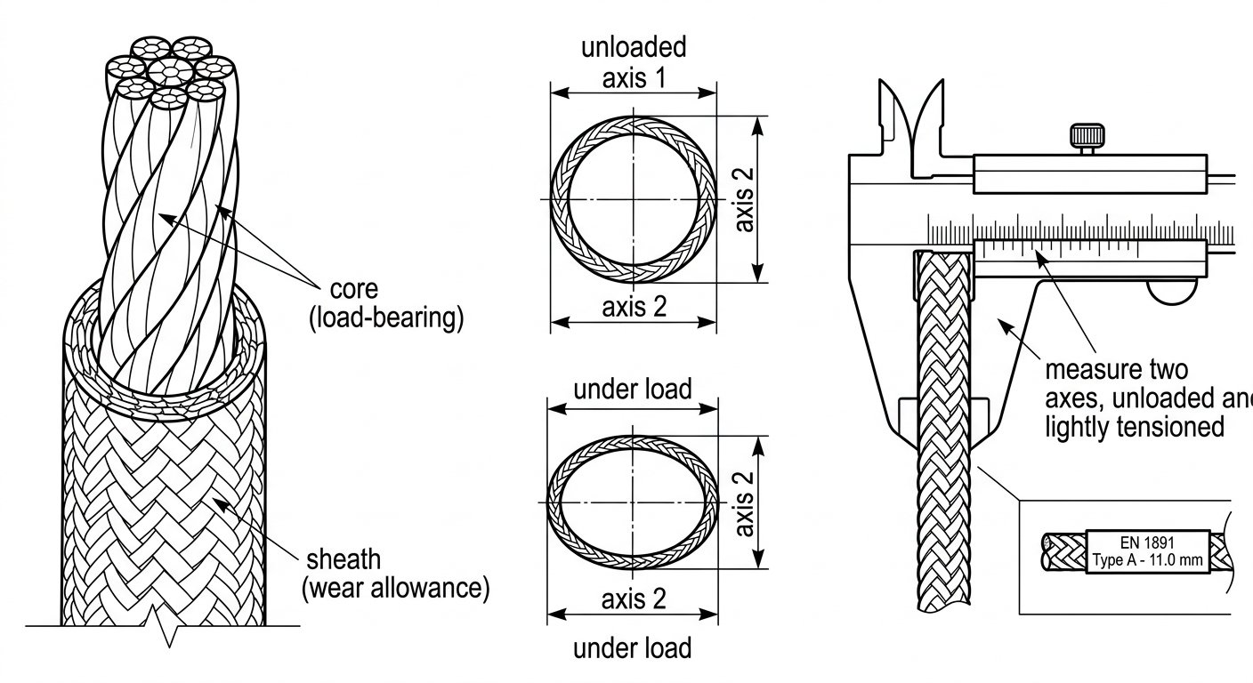
Nominal diameter is a label: measure across two axes, unloaded and under light tension, and read the type marking as well as the size.
Start from the hardware, not from the rope
The usable diameter window for a system is the intersection of the marked rope diameter ranges of every device that runs on that rope. Rope adjustment devices for rope access — backup devices, ascenders and descenders — are certified under EN 12841 as Type A, B and C rope adjustment devices, and each one carries a marked diameter range specific to that model. Descenders intended for lowering a person in rescue also carry a marked range under EN 341 for rescue descender devices, and that range is not always identical to the same device’s working-descent range.
Build the window explicitly rather than assuming. List every item that touches the rope: descender, backup device, foot and hand ascenders, any rope grab used on a fixed line, progress-capture devices, pulleys and edge rollers. Note the marked range for each. The overlap is what you can buy. It is common for the descender or the backup device to be the narrowest constraint and for the ascenders to be relatively tolerant — so if one device dictates 10.5 mm to 11.5 mm, that is the system diameter, even if everything else would accept 9 mm.
Two further constraints often get missed. First, some devices are rated across a range but only certified for a narrower band for a specific function, such as two-person loads or use with a stretcher. Second, the rope grab or backup device is only part of the picture — how it is attached matters too, which is covered in the note on choosing the harness attachment point for a rope grab.
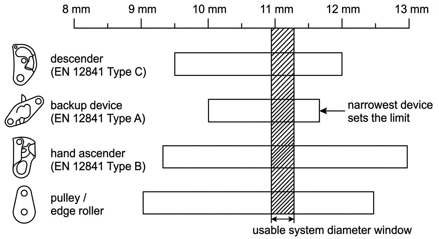
The usable diameter is the intersection of the marked ranges of every device that runs on the rope, not the range of the most tolerant one.
What actually changes as diameter goes down
Within the range a device accepts, thinner rope is not simply a lighter version of thicker rope. The trade-offs are consistent across manufacturers:
- Less friction in the device. A thinner rope typically runs faster through a descender at the same brake-hand effort and generates more heat per metre in the friction surfaces. On long descents this is the practical limit, not rope strength.
- Less to hold onto. Braking by hand on a thin rope, especially wet or with gloves, is harder to modulate. Anyone who has moved from 11 mm to 9 mm notices this on the first descent.
- Smaller abrasion margin. Sheath is a wear allowance. On a thin rope, a given depth of edge abrasion or glazing removes a larger proportion of the total cross-section and reaches the core sooner.
- More sensitivity to sheath condition. Grabbing devices rely on the sheath. A rope already near the bottom of a device’s marked range, with a worn, compacted or dirty sheath, gives the device less to bite on.
- Lower mass. The genuine advantage: less weight to carry, haul and manage, which matters on long lines, tower work and repeated shaft descents.
Going thicker reverses all of it: more friction and more controllable descent, a larger wear allowance, easier handling in gloves, but more weight, more bulk in knots and haul systems, more friction in redirects and pulleys, and, near the top of a device’s range, real difficulty installing the rope at all — particularly with a new, stiff, slightly oversized rope in cold conditions.
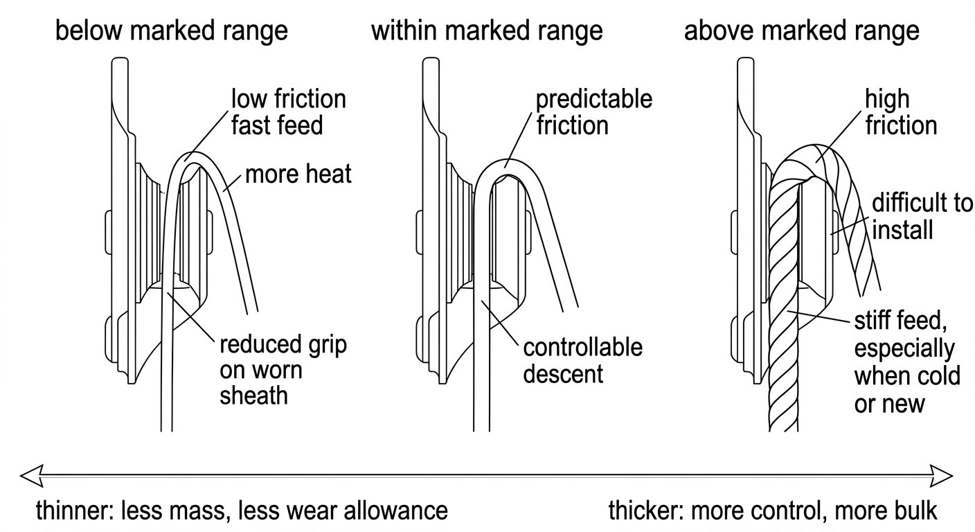
Diameter changes friction and heat before it changes strength: below range the rope runs fast and grips poorly, above range it may not feed at all.
Typical working bands
Practice varies between contractors, jurisdictions and equipment sets, so treat the following as how the market tends to be organised rather than as prescriptive limits. Always defer to the marked ranges on your own devices.
- Around 8–9 mm. Lightweight and specialist use, only with devices explicitly marked for that diameter. Attractive on weight-critical jobs; unforgiving on friction control, abrasion and sheath wear. Frequently Type B, which restricts what it may be used for.
- Around 9–10.5 mm. Lighter access work, long fixed lines and situations where rope mass is a genuine constraint. Requires devices rated to the lower end and disciplined inspection.
- Around 10.5–11.5 mm. The workhorse band for industrial rope access. The widest choice of devices, the best balance of friction, handling and wear allowance, and the diameter most training and most manufacturer guidance assumes.
- Around 11.5–13 mm. Rescue and stretcher systems, training rigs, high-wear installations, permanently rigged lines and anywhere abrasion or long service life dominates. Heavier, bulkier, and it may exclude some smaller devices entirely.
In confined-space entry, diameter choice interacts with the whole retrieval arrangement — tripod or davit head sheave, winch or man-riding device, and the space available at the opening. Settle the rope diameter alongside the rest of the entry plan rather than after it; the sequence for that planning is set out in the note on the confined space entry permit sequence.
Two-person and rescue loads
Adding a second person, or a stretcher and attendant, changes the friction requirement more than it changes the strength requirement. The descender has to dissipate roughly double the energy over the same distance, and thin rope makes that harder to control. Manufacturers usually publish a separate, narrower diameter range and a separate maximum load for rescue or two-person use, and often specify additional friction. Check that specific guidance for the actual device rather than extrapolating from the single-person range. If a site has a credible rescue plan involving a lowered stretcher, size the rope for that scenario, not for routine descent.
Field check before you commit
Nominal diameter is a label. Before a rope enters service on a given set of devices, verify it:
- Measure it. Use a caliper on an unloaded section, then on a lightly tensioned section, and take readings on two axes at the same point. Kernmantel rope is not perfectly round, and it flattens slightly under load.
- Measure it again in service. New rope often measures above nominal and reduces as the sheath beds in and compacts. A rope that started comfortably mid-range can drift toward the bottom of a device’s range over its life.
- Read the end marking and the type. Confirm EN 1891 Type A or Type B, the manufacturer, and the diameter as marked. Confirm it against the device markings, not against memory.
- Function test on the actual rope. Install the descender and the backup device on that rope and load them at ground level or in a low-consequence position. Check that the descender feeds smoothly and holds, and that the backup device engages and releases as it should. A device at the extreme of its range on an unusually stiff or unusually soft rope sometimes behaves differently from the same device on the rope it was demonstrated with.
- Check the connectors too. Rope diameter influences descender geometry and therefore how the attachment connector is loaded; see the note on choosing a connector for a descender.
Keep the working line and backup line consistent
Where a system uses a working line and a separate backup line, using the same diameter, type and ideally the same model of rope on both is the simpler and safer arrangement. It keeps a single diameter window for the whole system, means a rope can be swapped between roles without re-checking device markings, and gives predictable device behaviour if the load transfers to the backup. Mixing diameters is sometimes unavoidable on rigged installations, but it should be a deliberate, documented decision with each device verified against the rope it will actually run on — not the result of grabbing whatever was in the bag.
Record diameter, type, manufacturer, length and date of first use in the rope log alongside the rest of the PPE records, and mark rope ends so diameter can be identified on site without a caliper. That record is what allows a supervisor to confirm, quickly, that the rope on the anchor matches the devices on the technician.
Takeaway
Work in this order: identify every device that will run on the rope, take the intersection of their marked diameter ranges, decide within that window based on descent length, abrasion exposure, load case and how much rope mass the job can tolerate, then verify the specific rope with a caliper and a function test before it goes into service. Related selection notes on devices, connectors and harnesses are collected on the rope access and confined space technique notes hub.
Frequently asked questions
What is the difference between EN 1891 Type A and Type B rope?
Both are low stretch kernmantel ropes, but Type A is the general-purpose working rope for industrial rope access and Type B is a lighter-duty rope with lower strength requirements and a smaller minimum diameter, intended for more restricted use and lower loads. Type A ropes start at 8.5 mm and Type B at 8 mm, so diameter alone does not tell you which type you have. Read the end marking and the manufacturer’s data sheet before putting a rope into a system.
Which diameter is the default for industrial rope access?
Most industrial rope access work sits in the region of 10.5 mm to 11.5 mm. That band has the widest choice of certified devices, a good balance of friction, handling and abrasion allowance, and it is what most training and most manufacturer guidance assumes. The final choice must still fall inside the marked diameter range of every device on the rope.
Can I use a rope that is slightly outside my descender’s marked diameter range?
No. The marked range is the range the device was tested and certified with, and behaviour outside it is not verified: too thin gives reduced friction and grip, too thick may not install or feed properly. Either change the rope or change the device so the whole system falls inside a single verified window.
Why is thinner rope harder to descend on?
A thinner rope generally passes through a descender with less friction at the same brake-hand effort, so it runs faster and puts more heat into the friction surfaces over a long descent. It also gives less to hold and modulate by hand, particularly when wet or in gloves. Thin rope can be entirely appropriate, but it usually needs added friction and more disciplined technique.
Should the working line and the backup line be the same diameter?
Keeping both lines the same diameter, type and preferably the same model is the simpler and safer arrangement. It gives one diameter window for the whole system, allows a rope to be swapped between roles without re-checking device markings, and makes device behaviour predictable if the load transfers to the backup. Mixing diameters should be a deliberate, documented decision with each device verified against the rope it will actually run on.
Does rope diameter change over its service life?
Yes, in practical terms it does. New rope often measures slightly above its nominal diameter and reduces as the sheath beds in, compacts and wears, so a rope that started mid-range can drift toward the bottom of a device’s range. Re-measure periodically as part of inspection, and treat a worn or glazed sheath as a further reduction in the grip available to rope grabs and backup devices.