
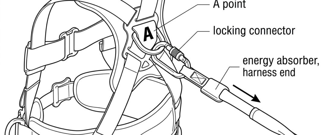
The connection between a lanyard and a harness is the one link in a fall-arrest system that the user makes and unmakes by hand, several times a shift, often in awkward positions and poor light. It is also the link most likely to fail silently: the system looks connected, the worker feels connected, but the load path runs through a point or an axis that was never designed to take a fall. This note covers which harness attachment points are valid, which connector belongs at the harness end, how to load it, and the specific errors that recur on site.
Only points marked A are fall-arrest attachment points
A full body harness certified to EN 361 (Full Body Harnesses) carries its fall-arrest attachment points marked with a capital A. In practice there are two arrangements:
- Dorsal A — a single attachment point between the shoulder blades, either a metal D-ring or a sewn textile loop.
- Sternal A — a chest attachment, either as one full attachment point, or as a pair of loops each marked A/2. Where the marking is A/2, the two halves form one attachment point only when both are captured by the same connector. Clipping into one A/2 loop alone is not a fall-arrest connection.
Everything else on the harness is for something other than arresting a fall: waist side D-rings for work positioning, a ventral point for suspension and rope access, elastic keepers and tool loops for carrying. A rescue attachment on a harness certified to EN 1497 (Rescue Harnesses) is intended for lifting and evacuating a person, not for taking a fall.
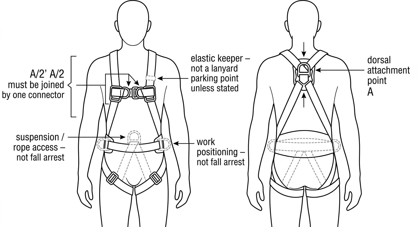
Only attachment points marked A are fall-arrest points; where they are marked A/2, both loops must be captured by the same connector.
Sternal or dorsal: how the choice is made
Both A points arrest a fall. They do not do it the same way, and the decision is driven by the equipment and the work position, not by convenience.
- Dorsal is the default for a lanyard running to an anchor at or above head height, and for work where any slack line in front of the body would snag or trip. It keeps the lanyard behind the worker and out of the working area, and it tends to leave the body in a more upright post-fall posture. Its disadvantage is that the user cannot see the connection or verify it without help.
- Sternal is normal with guided type fall arresters on a rigid or flexible anchor line — ladder and mast climbing — and wherever the user must be able to see and check the connection. It is also easier to reach when the harness is worn under other PPE.
Whichever point is used, the harness must be adjusted so it stays there. A dorsal ring that has migrated low onto the small of the back, or a chest attachment left slack because the shoulder straps are long, changes the geometry of the arrest. Fit checks are covered separately in Adjusting a Full Body Harness Correctly.
The harness-end connection itself
Lanyards reach the harness in one of three ways, and each has its own rule.
1. A connector supplied with the lanyard
Most energy-absorbing lanyards terminate in a sewn loop taking a connector to EN 362 (Connectors for Fall Protection). At the harness end, a small locking connector — screw-lock or auto-lock — is normal. The gate must be closed and locked before the connection counts; a screw sleeve that is not run down to its stop is an open connector. The trade-offs between sleeve types are set out in Connector Locking Systems Compared.
2. A captive or semi-permanent connector
Some lanyards are supplied with a connector held captive on the harness-end loop by a bar or retaining pin. This is the preferred arrangement where it exists, because it removes the possibility of the connector rotating out of position or being loaded across the gate. If the retaining bar is missing or broken, the connector is no longer captive — it is a normal connector with a hole in it, and it should be replaced.
3. Direct textile-to-textile connection
A sewn lanyard loop passed through a textile harness attachment and back through itself — a girth hitch, sometimes called a lark’s foot — is only acceptable where both manufacturers explicitly permit it and describe it. Improvised as a field solution, it loads webbing across webbing at a tight radius and can reduce strength significantly. Never knot a lanyard onto an attachment point, and never pass a sewn loop through a metal D-ring and back on itself unless the instructions show that configuration.
Under no circumstances chain two connectors together to reach the attachment point. Connector-to-connector links can lever open, sit on their minor axis, and add length to an assembly whose length is fixed by design.
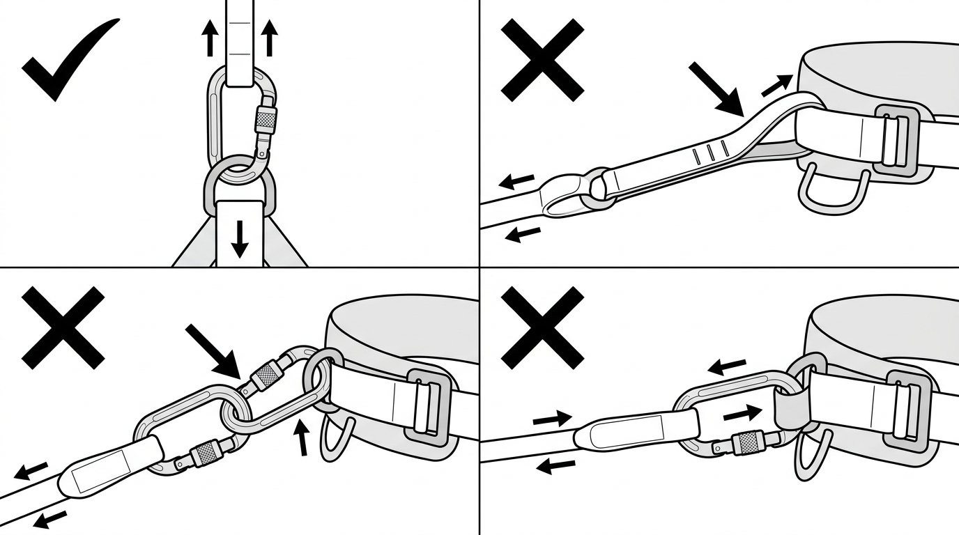
One locking connector, loaded along its major axis; no lark’s foot, no connector chained to connector, no gate pressed against the harness.
Loading the connector on the right axis
A connector at the harness end lives in a crowded space: webbing, a D-ring or textile loop, sometimes a chest strap and a radio harness in the same handful. Three loading errors are common there:
- Cross-loading. The connector ends up loaded across its width rather than along its major axis — typically because it has rotated so the spine lies flat against the harness. A connector’s rated minor-axis strength is a fraction of its major-axis strength.
- Gate-loaded or gate-pressed. The gate rests against a D-ring, a buckle or a stiff strap, so that load or movement pushes on the gate rather than the spine.
- Three-way loading. The connector is asked to hold the lanyard, a bag strap and something else at once, so no single load line runs along the axis.
The test on site is simple: with the connector clipped and locked, the assembly should be able to align itself along its major axis without being trapped. If the connector cannot rotate into line, it is captured, and captured connectors are loaded wherever they happen to be sitting. Working through shape and geometry before clipping in is described in Checking Connector Compatibility: A Field Method Before You Clip In.
Two-leg lanyards: one attachment point, and park the spare leg
A twin-leg (Y) lanyard exists so the user can stay connected while moving between anchors. Two rules govern its harness end.
Both legs go to the same single A point. On most twin lanyards the energy absorber sits at the harness end and is shared by both legs, so splitting the legs between two attachment points — or between an A point and a belt D-ring — bypasses the intended load path.
The unused leg is parked on a dedicated parking attachment. Harnesses designed for twin lanyards typically provide purpose-made parking points, often designed to release or tear away if the parked leg is accidentally loaded, precisely so that a fall onto the spare leg is not taken by the harness in the wrong place. Do not park an unused leg on:
- the A attachment point in use (it clutters the connection and can cross-load it);
- a waist side D-ring intended for work positioning under EN 358 (Work Positioning and Restraint Belts), which is not a fall-arrest point;
- a tool loop, gear loop or elastic keeper not stated to be a lanyard parking point.
A leg left hanging free is its own hazard — it snags on rungs and rotating plant, and a heavy hook swinging at knee height is a trip and strike risk on a ladder.
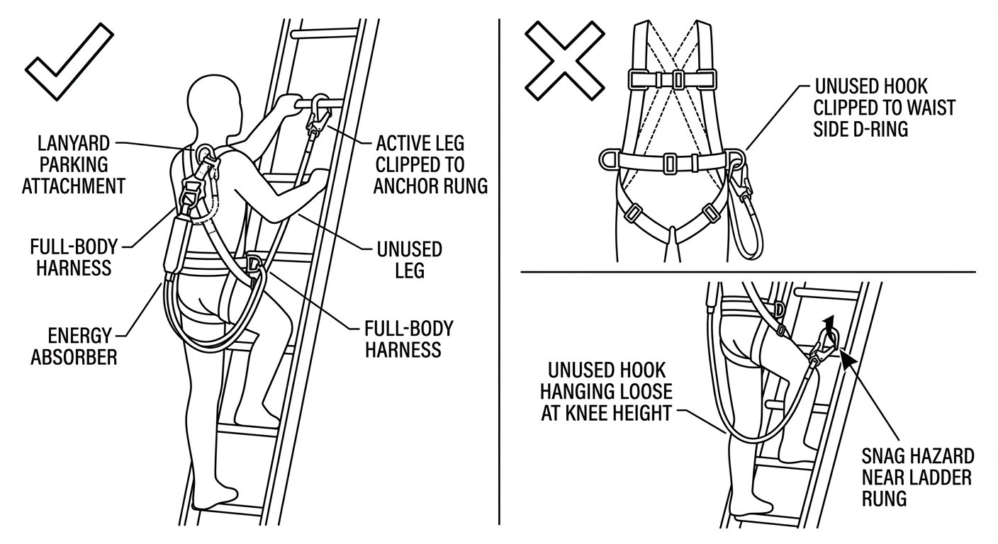
Both legs of a twin lanyard share one A point; the unused leg goes on a designated parking attachment, never on a positioning D-ring.
Do not add length to the assembly
An energy-absorbing lanyard to EN 355 is certified as a complete assembly, and the standard limits that assembly — absorber, lanyard and connectors together — to a total of 2 m. Adding an extra connector, a short sling or a second lanyard to bridge a gap does three things at once: it lengthens the free fall, it increases the clearance required below the working level, and it invalidates the certification of the assembly as tested.
The same applies to the position of the energy absorber. Fit it as the manufacturer’s instructions show; where the absorber is designed to sit at the harness end, keep it there rather than reversing the lanyard so the absorber ends up at the anchor. If the required clearance stated in the instructions is not available below the work position, the answer is a different system — a retractable device, a shorter restraint arrangement, or a higher anchor — not a modified lanyard. Selection is covered in Which Type of Fall-Arrest Lanyard to Choose.
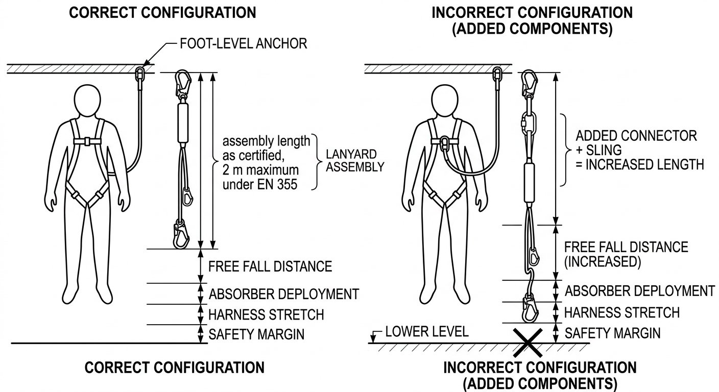
Extra connectors added at the harness end lengthen the free fall and eat into the clearance the assembly was certified to need.
Pre-use check at the harness end
Before each use, at the harness end specifically:
- Confirm the attachment point is marked A, and that both halves are captured if it is marked A/2.
- Confirm the connector is closed and the sleeve fully locked — by sight and by feel, not by assumption.
- Check the connector can align on its major axis and that the gate is not pressed against webbing, a buckle or a D-ring.
- Check the sewn termination and any protective sleeve for cut, abrasion, chemical marking, heat damage or exposed thread; check the retaining bar on a captive connector.
- Confirm the energy absorber is intact, unopened, its indicator undeployed and its cover not torn or wet-hardened.
- Confirm the spare leg of a twin lanyard is on a designated parking point.
Any deployed absorber, any lanyard that has arrested a fall, and any connector with a sticking gate or damaged sleeve is withdrawn from service — not stored “for training”.
Next
The other end of the same lanyard has its own set of rules, particularly around gate opening size and roll-out on structural steel: see Lanyard-End Connector for Fall Arrest: Gate Opening, Roll-Out and Correct Loading. The full set of technique notes is indexed on the rope access and confined space hub.
Frequently asked questions
Can a fall-arrest lanyard be attached to the waist side D-rings of a harness?
No. Waist side D-rings are work-positioning and restraint attachments covered by EN 358, and they are not designed or marked for arresting a fall. A fall-arrest lanyard connects only to an attachment point marked A, or to a pair of A/2 loops used together.
Is the sternal or the dorsal attachment better for a fall-arrest lanyard?
Both are valid fall-arrest points, and the choice follows the equipment and the work position. Dorsal is the usual choice for a lanyard to an overhead anchor because it keeps the line clear of the work area; sternal is normal with guided type fall arresters on ladders and masts, and where the user needs to see and check the connection.
Can the lanyard’s sewn loop be girth-hitched (lark’s foot) directly onto the harness attachment point?
Only where both the harness and lanyard manufacturers explicitly permit and illustrate that configuration. Improvised, a girth hitch loads textile across textile at a tight radius and can reduce strength, so the default is a connector conforming to EN 362 or a captive connector supplied with the lanyard.
What should be done with the unused leg of a twin-leg lanyard?
Stow it on the harness’s designated lanyard parking attachment, which on many harnesses is built to release if the parked leg is accidentally loaded. Do not park it on the A point in use, on a positioning D-ring, or on a tool loop, and do not leave it hanging loose where it can snag or strike.
Is it acceptable to add a connector or a short sling to reach an anchor that is slightly out of range?
No. An energy-absorbing lanyard is certified as a complete assembly, and EN 355 limits that assembly — absorber, lanyard and connectors — to 2 m in total. Adding length increases free fall and required clearance and takes the assembly outside the configuration it was tested in; the correct answer is a different system or a better-placed anchor.
How can a connector at the harness end be checked for correct loading?
With the lanyard clipped and the sleeve fully locked, the connector should be free to rotate into line with the direction of pull so that load runs along its major axis. If it is trapped by webbing, a buckle or a second item so that the gate is pressed or the load crosses the minor axis, reposition or change the connector.