
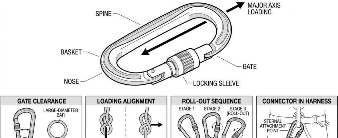
Most connector problems on site are not strength problems. A locking carabiner marked to EN 362 (Connectors for Fall Protection) has ample margin for the loads a rope access or confined-space system will generate — provided it is loaded along its major axis, with the gate closed and locked, against something it actually fits. Compatibility is the process of confirming those conditions will still hold once the system is loaded, moving, and out of sight. Checking connector compatibility takes seconds at the anchor and prevents the failure modes that do occur in practice: cross-loading, gate roll-out, unlocked sleeves, and connectors jammed sideways in an eye that is too wide for them.
This note sets out a repeatable sequence of checks to run every time a connector is paired with a new anchor, device, textile eye, or another connector.
The four questions behind every compatibility check
Whatever the hardware, the assessment reduces to four questions, in this order:
- Does it physically fit? Can the gate open wide enough to admit the attachment point, and is there room for that point to sit in the basket of the connector?
- Will it stay aligned? Once loaded, does the connector settle onto its major axis, or is it held in a position that loads the minor axis or the gate?
- Can anything act on the gate? Is there any geometry — an edge, a large-radius bar, a device side plate, a second connector — that could press the gate open or work the locking sleeve loose?
- Is the pairing appropriate over time? Locking type suited to the use, and materials that will not chew each other up over a shift or a season.
Check 1: gate opening and basket clearance
The first constraint is simply dimensional. A connector’s gate opening determines the largest structure it can be clipped onto; the internal width of the basket (the load-bearing curve opposite the gate) determines whether that structure can sit properly once inside. Both matter, and they fail differently.
- Too small an opening is obvious — the connector will not go on. This is common with structural steelwork, large-diameter pipe, scaffold tube collars and wide anchor eyes, and is the normal reason to reach for a large-opening steel connector or a sling around the member instead.
- An opening that just barely admits the structure is the hazardous case. The connector goes on, but the anchor sits tightly against the gate rather than in the basket, and there is no room for the connector to rotate into alignment under load.
The working rule: the attachment point must be able to sit in the basket, clear of the gate and clear of the nose, with room to move. If you have to force, twist, or hold the connector in position to make it fit, it is not compatible with that anchor.
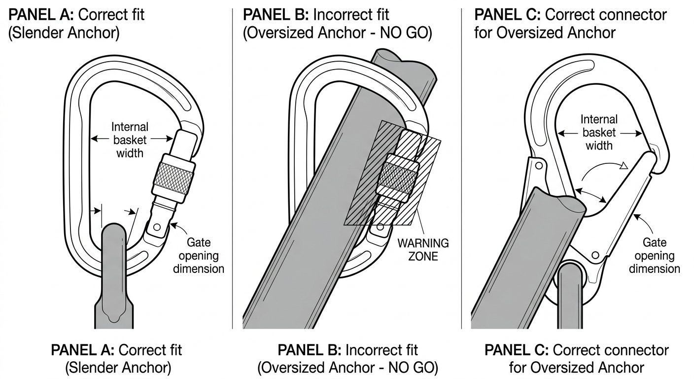
The attachment point must sit in the basket with clearance from the gate — an opening that only just admits the anchor is the hazardous case.
Check 2: does it settle onto the major axis?
Connectors are designed to be loaded lengthwise, gate closed. Minor-axis (cross) loading and gate-open loading both reduce strength substantially — this is why manufacturers mark the correct loading direction on the frame and why the shape of the connector is chosen for the job. If you are unsure which shape belongs where, see the note on connector shapes and where each belongs.
Compatibility failures that produce bad alignment usually look like one of these:
- Three-way loading. A connector taking a load from three directions — for example one carabiner holding a backup device, a lanyard and an anchor sling simultaneously — cannot align with any of them. Split the connections onto separate connectors or onto a rigging plate.
- Captured geometry. The connector is trapped between two rigid surfaces (device side plates, a bracket, a narrow anchor eye welded flat) so it cannot rotate as the direction of pull changes.
- Wide textile eye, narrow connector. A stiff or bulky sling eye can wedge the connector into a fixed attitude, or spread it so the load bears on the sides of the frame rather than along its length.
The test is behavioural, not theoretical: apply body weight, watch what the connector does, then change the direction of pull through the range the system will actually see and watch again. A compatible connector rolls into line and stays there.
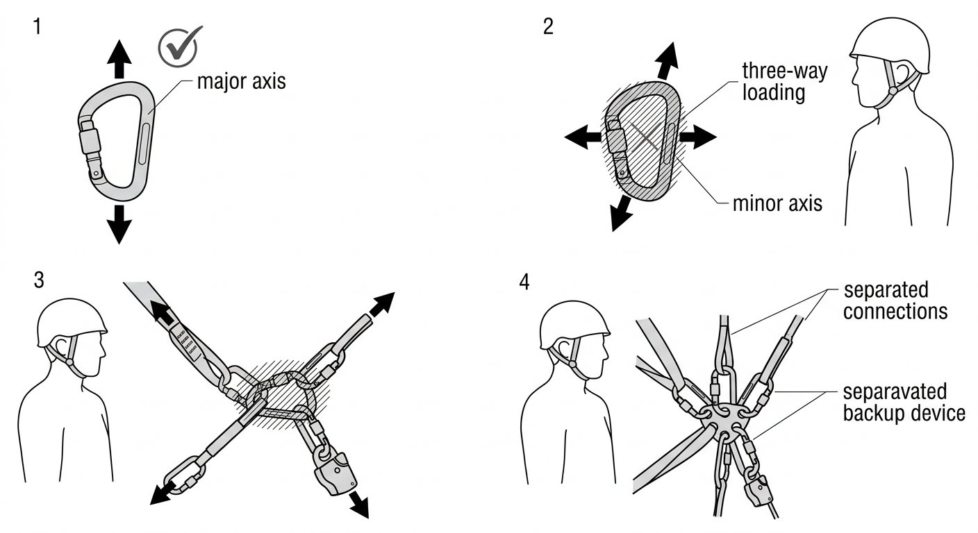
A compatible connector rotates into major-axis alignment on its own; three-way loading makes that impossible.
Check 3: gate interference and roll-out
Roll-out is the sequence in which a connector, loaded across an edge or a large-radius object, rotates until the nose or gate bears on that object, the gate is levered open, and the connector unhooks itself. It needs three conditions: a shape mismatch, freedom to rotate, and a gate that can be pushed open. Removing any one of the three removes the hazard.
Look specifically for:
- Anchors with a radius similar to the connector’s internal dimensions — a fat eye bolt, a rolled beam edge, a padeye lip. The connector cannot lie flat against them and will try to climb.
- Devices or brackets that press on the sleeve. A rope-adjustment device to EN 12841 (Rope Access Adjustment Devices) or a descender frame sitting against a screw-lock sleeve can back the sleeve off over a shift, or hold a self-locking sleeve in the unlocked position.
- Connectors clipped through fabric loops that bunch over the gate. Webbing bearing on the gate rather than the basket is a slow, quiet source of gate loading.
Two engineering answers exist and both are worth knowing. The first is a captive-eye or restraining-bar connector, which keeps the connector’s position fixed relative to the device or harness attachment point so it cannot rotate into a roll-out attitude — this is why device-specific connectors exist and why the note on choosing a connector for a descender treats orientation as a first-order concern. The second is a shape or size change: a larger connector that can lie properly against the anchor, or a sling or soft link interposed between the connector and the offending geometry so the connector only ever sees textile.
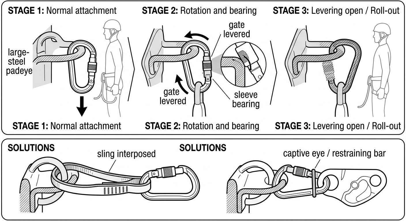
Roll-out needs a shape mismatch, freedom to rotate and a gate that can be pushed open — remove any one and the hazard goes.
Check 4: connector-to-connector and eye-to-eye pairings
Two connectors clipped directly to one another are a recurring compatibility problem. Each is now the other’s anchor, both are free to rotate, and either can find its way onto the other’s gate or nose. In most systems the cleaner solution is to connect through a textile element — a sling, a soft link, or a harness attachment point — or to use a single connector into the target eye and eliminate one link entirely.
Where a direct hardware-to-hardware connection is unavoidable, check that the pairing cannot bind: a small connector inside a large one will slide to the small one’s nose region; a narrow connector through a thick, stiff eye may not be able to align at all.
The harness end deserves its own look. Attachment points differ in thickness, stiffness and width — a sternal textile loop, a dorsal D-ring on a harness to EN 361 (Full Body Harnesses), a ventral aluminium ring, a rescue attachment to EN 1497 (Rescue Harnesses). A connector that sits perfectly in one may be pinched or held sideways in another. Check each combination once, properly, before it becomes routine; correct harness setup is covered separately in the note on adjusting a full body harness correctly.
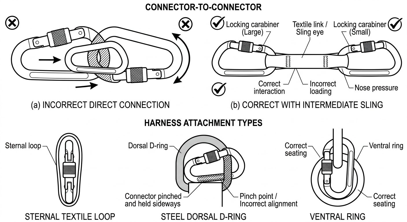
Hardware clipped directly to hardware can bind or migrate onto a nose; a textile element between them restores free alignment.
Locking system and material pairing
Compatibility also includes the choice of locking mechanism, which is a use-case decision rather than a dimensional one. Connections made once at the start of a shift and left alone — an anchor connector, a device attachment — favour a screw-lock or three-stage mechanism. Connections made and broken repeatedly during progression favour a self-locking sleeve. The trade-offs, and the specific hazards of each, are set out in connector locking systems compared.
Materials matter mainly through wear. Aluminium alloy connectors are light and appropriate for most personal system connections, but they wear quickly against steel — a rolled steel beam, a galvanised anchor eye, a gritty steel shackle. Where a connector will bear directly on steel structure, sit on an abrasive edge, or stay rigged in one place for a long period, a steel connector or an intermediate sling is the better pairing. Inspect aluminium connectors that live against steel more often than the rest of the kit, and retire them on the manufacturer’s wear criteria rather than by feel.
A pre-use sequence you can run in under a minute
- Read the marking. Confirm the connector is certified for the intended use and note the marked loading direction.
- Offer it up. Does the gate open wide enough, and does the attachment point drop into the basket without force?
- Close and lock. The gate must close fully and the sleeve must lock without being held, with nothing bearing on it.
- Weight it. Apply load and confirm the connector rotates into major-axis alignment on its own.
- Sweep the direction of pull. Move through the angles the work will actually produce and confirm the connector stays aligned and clear of the gate.
- Look for interference. Nothing on the gate, nothing on the sleeve, no third load path.
Any step that fails is a stop. The fix is almost always a different connector, a different shape, or a sling — not a workaround, and never holding a connector in position by hand or with tape while it is loaded.
Confined-space specifics
Inside a vessel or a chamber, two things change. Visibility drops, so the load-and-observe test becomes more important than the visual one — you may not be able to see the connector once the entrant is through the portal. And the anchors are often whatever the structure offers: internal ladder rungs, agitator mounts, nozzle flanges, tank internals with radii and edges that no connector was designed for. Assume large-radius and edge-loaded anchors until proven otherwise, and rig a sling to the structure so that the connectors in the personal system only ever see a textile eye. Where entry is planned rather than improvised, connector compatibility belongs in the pre-entry equipment check described in the confined space entry permit sequence.
Takeaway
Compatibility is a property of the pairing, not of the connector. A connector that is ideal in one position can be the weakest element in the system one clip away, and the difference is visible in seconds if you load it and watch. Fit, alignment, gate clearance, locking type, materials — in that order, every time a new combination appears.
Further technique notes on connectors, devices and entry procedure are collected on the rope access and confined space technique index.
Frequently asked questions
What does connector compatibility actually mean?
It means the connector, once loaded, will sit on its major axis with the gate closed and locked, against an attachment point it physically fits. Compatibility is a property of the pairing rather than of the connector alone — the same carabiner can be correct at one attachment point and the weakest link at the next.
Can I clip two carabiners directly together?
It is generally best avoided. Each connector becomes the other’s anchor, both are free to rotate, and either can end up loaded on the other’s gate or nose. Connecting through a textile element such as a sling, soft link or harness attachment point, or eliminating one connector altogether, is the cleaner solution.
What is roll-out and how do I prevent it?
Roll-out is when a connector loaded against an edge or a large-radius object rotates until the object levers the gate open and the connector unhooks. It requires a shape mismatch, freedom to rotate and a gate that can be pushed open. Use a larger or differently shaped connector, a captive-eye or restraining-bar connector, or interpose a sling so the connector only bears on textile.
Does it matter whether a connector is steel or aluminium?
Mainly for wear. Aluminium alloy connectors are light and suit most personal system connections, but they abrade quickly against steel structure and galvanised anchors. Where a connector bears directly on steel, sits on an abrasive edge, or stays rigged in one place for long periods, use a steel connector or an intermediate sling, and inspect more frequently.
How do I check compatibility if I cannot see the connector once the worker is in the space?
Do the check outside the space, under load. Weight the connection, sweep the direction of pull through the range the work will produce, and confirm the connector stays aligned and clear of the gate. In confined spaces it is also good practice to sling the structure so the connectors in the personal system only ever attach to a textile eye.
Which locking system should I choose for a given connection?
Connections made once and left alone for a shift — anchor connectors, device attachments — favour screw-lock or three-stage locking. Connections made and broken repeatedly during progression favour a self-locking sleeve. In both cases confirm nothing bears on the sleeve, since a device frame or bunched webbing can back off a screw-lock or hold a self-locking sleeve unlocked.