
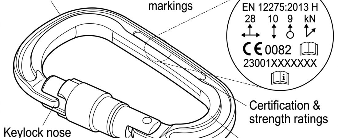
A connector that has been picked out of a kit bag tells you almost everything you need to know about whether it belongs in the system you are about to build — but only if you can read it. The letters, numbers and pictograms stamped or laser-etched into a carabiner body are not decoration or factory housekeeping: they identify the standard the connector was certified to, the class of use it was designed for, the direction it is meant to be loaded in, and the individual item for traceability purposes. Learning to read those markings in a few seconds, before clipping in, is one of the cheapest habits in rope access and confined-space work.
This note covers what appears on a typical fall-protection connector, how to interpret each element, and what the markings deliberately do not tell you.
What is normally marked on a fall-protection connector
A connector certified as personal protective equipment in Europe carries a cluster of information, usually along the spine, on the gate, or on the locking sleeve. The exact layout varies between manufacturers, but the same elements recur:
- Manufacturer or brand identification — a name or logo.
- Model or product reference — the manufacturer’s own designation for that specific connector.
- The standard and its class letter — for example
EN 362:2004/B. The year identifies the edition of the standard; the letter identifies the class of connector. - Strength figures in kN — typically the minimum breaking strength on the major axis, and often the minor-axis and gate-open figures as well, each paired with a small pictogram showing the loading condition.
- CE mark, and for fall-protection equipment (a Category III PPE product) a four-digit number identifying the notified body responsible for production surveillance. Depending on the market, a UKCA mark and its own body number may also appear.
- An individual serial number and/or batch number, and in most cases a date or date code of manufacture. This is what links the item in your hand to a specific inspection record.
- A “read the instructions” pictogram — the small open-book symbol. It is not a formality: connector-specific limits on loading and compatibility live in that leaflet.
On small or complex-shaped connectors, part of this information migrates to the gate, the sleeve, or a laser-etched panel on the inside of the frame, so it is worth turning the connector over rather than concluding a marking is absent.
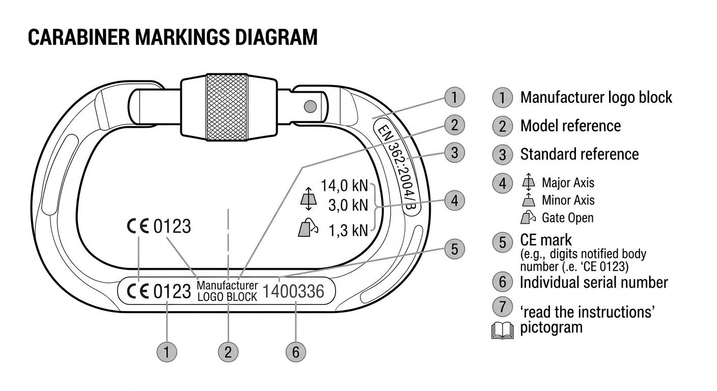
A typical marking cluster on the spine of a fall-protection connector, element by element.
The class letter is the most decision-relevant marking
Of everything stamped on the frame, the class letter after the standard number is the piece most likely to change what you do next. Under EN 362, the European standard for fall-protection connectors, connectors are divided into classes according to intended use:
- Class B — basic connector. A general-purpose connector intended to be used as a component of a system.
- Class A — anchor connector. Designed to attach directly to a specific type of anchor, such as a scaffold tube, girder flange or reinforcing bar. Large steel hooks and girder hooks commonly fall here.
- Class M — multi-use connector. Intended to be loadable along more than one axis, and accordingly tested on the minor axis as well as the major axis.
- Class T — termination connector. Designed to be loaded in one predetermined direction only, typically as an element of a subsystem such as a lanyard end. Captive-eye and directional connectors are usually in this class.
- Class Q — screw-link connector. A maillon-type link closed by a threaded nut, intended for long-term or semi-permanent connections. The nut must be fully screwed home for the marked strength to apply.
Reading T on a connector tells you it expects a single, controlled loading direction and should not be left free to rotate into a cross-load; reading Q tells you the closure is a nut that will not close itself if you forget it. Neither of those facts is obvious from the shape alone, which is why the letter matters. The relationship between class, shape and intended position in the system is developed further in Connector Shapes and Where Each Belongs.
Connectors marked to EN 12275 instead of EN 362 are certified as mountaineering equipment and use a different letter set (B for basic, H for HMS, K for via ferrata, X for oval, Q for screw-link, D for directional, A for anchor). Some products are dual-marked to both standards. If the only standard reference on a connector is EN 12275, it has not been assessed against the fall-protection standard, and whether it is acceptable in your system is a question for the employer’s procedure and the manufacturer’s instructions rather than an assumption.
Reading the strength figures and their pictograms
Strength markings are almost always given in kilonewtons and are usually accompanied by a small silhouette showing how the load was applied. Three conditions appear most often:
- Major axis, gate closed and locked — the load path along the spine, the way the connector is designed to work. EN 362 sets a minimum major-axis strength of 15 kN with the gate closed and locked; many aluminium and steel connectors are marked well above that figure.
- Minor axis (cross-loading) — load applied across the frame, gate to spine. Where marked, this figure is substantially lower than the major-axis value.
- Gate open — load along the major axis with the gate held open, representing a connector whose gate has been pressed open by the anchor, an edge or an adjacent component. This is typically the lowest of the three figures.
Climbing-standard connectors commonly carry all three figures as a group; fall-protection connectors sometimes carry only the major-axis value. The practical reading is the same either way: the marked major-axis figure is the number the design depends on, and the other two describe how much of that strength you throw away by letting the connector sit badly. That is the whole argument for controlling orientation, which is covered in Connector Basics: Gates, Axes and Loading.
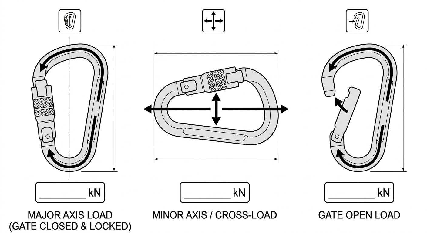
The three pictograms that accompany kN figures: major axis gate closed, minor axis, and gate open.
kN figures are not working loads
A marked kN value is a minimum breaking strength established under test conditions, not a permitted working load and not a rating you are meant to design towards. PPE connectors are sized so that the forces generated by a fall-arrest or rope-access system, together with the required safety margin, sit far below that figure. Treating a 22 kN marking as a licence to apply 22 kN is a category error.
This becomes an active hazard when lifting hardware finds its way into a personal system. Shackles, eyebolts and lifting hooks are marked with a working load limit in tonnes or kilograms, sometimes with a grade number, and are certified under a completely different regime. A shackle marked “1 t” is not the equivalent of a connector marked “20 kN”, and the absence of an EN 362 or EN 12275 reference on a piece of hardware is a clear signal that it was never assessed as fall-protection PPE.
Locking sleeve markings and closure type
The sleeve often carries its own information: an arrow or the word LOCK indicating the direction that closes a screw sleeve, or a small pictogram sequence showing the push–twist or push–twist–pull motion of a two- or three-stage automatic sleeve. On some models the sleeve also carries the serial number.
Markings do not, however, tell you whether the closure suits the task. A screw sleeve and a three-stage auto-lock sleeve can be identically marked EN 362:2004/B and carry identical strength figures while behaving very differently on a busy rope-access job. Selection between them is a separate decision, discussed in Connector Locking Systems Compared.
Where the markings live, and why placement matters
Marking placement is a design compromise. Deep stamping is durable but removes material, so manufacturers stamp only where the frame can tolerate it, and use laser etching or ink elsewhere. The consequences for the user are practical:
- On a plain oval or D-shape carabiner, most information is on the spine, running lengthwise.
- On a large HMS or pear shape, information may be split between spine and gate.
- On a captive-eye or directional connector, the class letter and the loading pictogram are frequently on the frame beside the captive bar — exactly the area that gets abraded by the webbing it is designed to hold.
- On a steel Class A hook, markings are usually on the wide part of the body or a raised boss, and are often the last thing to wear away.
- On a Class Q screw link, the markings are commonly on the barrel of the nut itself — which means fitting a replacement nut, or losing the original, destroys the identification.
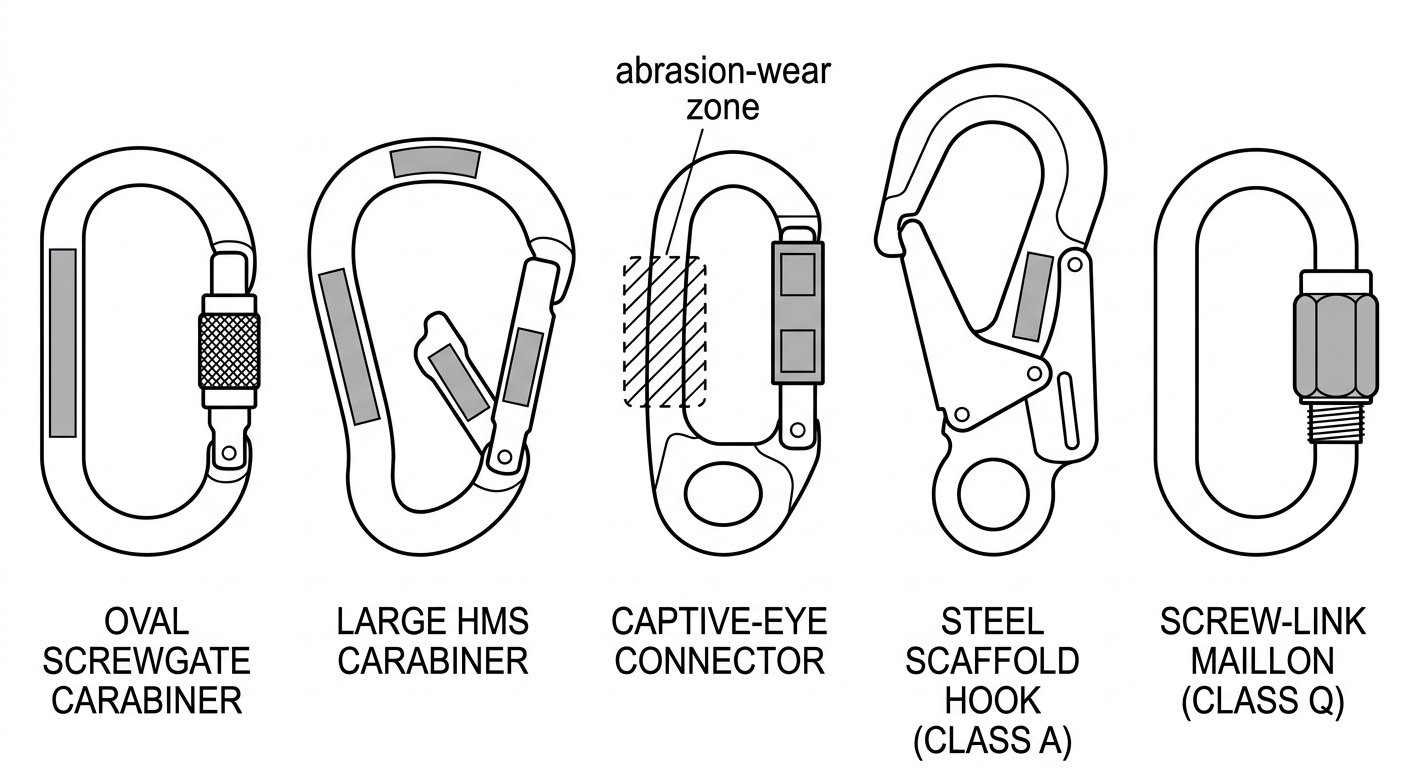
Marking locations differ by connector type — including on the nut of a Class Q screw link.
Illegible markings are an inspection finding, not a cosmetic issue
Traceability is part of what makes a connector usable. If the serial number can no longer be read, the item cannot be matched to its inspection history, and if the standard reference and class letter can no longer be read, the next user has no way of knowing what they are holding. Ink-printed markings on anodised aluminium are the usual casualty: rope friction, grit, solvents and repeated contact with a steel bar can erase them well before the metal itself is worn out.
Treat marking legibility as a check in its own right during pre-use and periodic inspection, alongside wear grooves, gate function, sleeve function and corrosion. Where markings are no longer legible, follow the manufacturer’s instructions and the employer’s inspection procedure on withdrawal — do not re-mark, engrave or paint identification onto a connector yourself, since both the metal and the certification are affected by doing so.
A reading order that takes about fifteen seconds
In the field, work through the markings in the order that most quickly rules a connector in or out:
- Standard and class letter. Is it certified for fall protection, and is the class consistent with where you intend to put it? A Class T lanyard-end connector and a Class A structural hook are not interchangeable.
- Major-axis strength. Confirm the marked figure is present and consistent with what the system requires.
- CE mark and notified body number. Present and legible.
- Serial or batch number. Readable, and matched to an inspection record for that item.
- Closure indication. Confirm the sleeve type and, on a screw sleeve, that it is fully closed once clipped.
- Physical fit. Markings do not confirm that the connector’s basket will sit correctly against the component it is attached to; that still needs a hands-on check, as set out in Checking Connector Compatibility: A Field Method Before You Clip In.
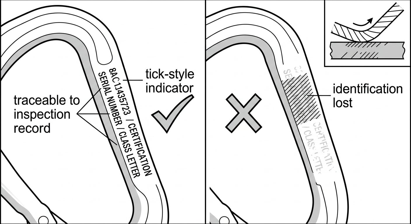
Markings worn illegible by rope friction break the link between the connector and its inspection record.
Takeaway
The markings on a connector answer three questions quickly: what standard and class is this, which way is it meant to be loaded, and which individual item is it. They do not answer whether the connector fits the anchor, whether the closure suits the task, or how much load you may apply — those remain judgement and procedure. Read the class letter first, treat kN figures as breaking strengths rather than working loads, and treat an unreadable serial number as a reason to set the connector aside rather than a blemish to ignore.
Further technique notes on connectors, harnesses and confined-space systems are collected on the rope access and confined space index.
Frequently asked questions
What does the letter after ‘EN 362’ on a carabiner mean?
It identifies the class of connector, which describes its intended use: A for anchor connectors that attach to a specific structure type, B for basic general-purpose connectors, M for multi-use connectors loadable on more than one axis, T for termination connectors designed for one predetermined loading direction, and Q for screw-link connectors closed by a threaded nut. The class letter is the marking most likely to change where you place the connector in a system.
Is the kN number marked on a connector its safe working load?
No. Marked kN figures are minimum breaking strengths established under test conditions, not permitted working loads. Personal fall-protection systems are designed so that the forces generated in use, plus the required safety margin, remain far below the marked figure. Hardware that carries a working load limit in tonnes instead — such as a shackle or lifting hook — belongs to a different certification regime and should not be substituted for PPE connectors.
What is the four-digit number next to the CE mark?
It identifies the notified body responsible for the ongoing production surveillance of that Category III PPE product. Fall-protection connectors fall into that category, so the number should accompany the CE mark. Depending on the market the connector was placed on, a UKCA mark with its own body number may also be present.
Can a connector still be used if the serial number has worn off?
Once the serial number is illegible, the item can no longer be matched to its inspection history, which is a traceability problem rather than a cosmetic one. Follow the manufacturer’s instructions and the employer’s inspection procedure on withdrawal. Do not stamp, engrave or paint your own identification onto a connector, as this can affect both the metal and the certification.
What is the difference between a connector marked EN 362 and one marked EN 12275?
EN 362 is the European standard for connectors used in fall-protection systems; EN 12275 covers connectors for mountaineering and climbing and uses a different class-letter set. Some connectors are dual-marked to both. If only EN 12275 appears, the connector has not been assessed against the fall-protection standard, and whether it may be used in a work system is a question for the manufacturer’s instructions and the employer’s procedure.
Why do some connectors show three kN figures and others only one?
Where three figures appear, they normally correspond to the major axis with the gate closed and locked, the minor axis (cross-loading), and the major axis with the gate held open — each paired with a small pictogram of that loading condition. Many fall-protection connectors are marked with the major-axis figure alone. In either case, the major-axis value is the one the design relies on, and poor orientation reduces the strength actually available.