
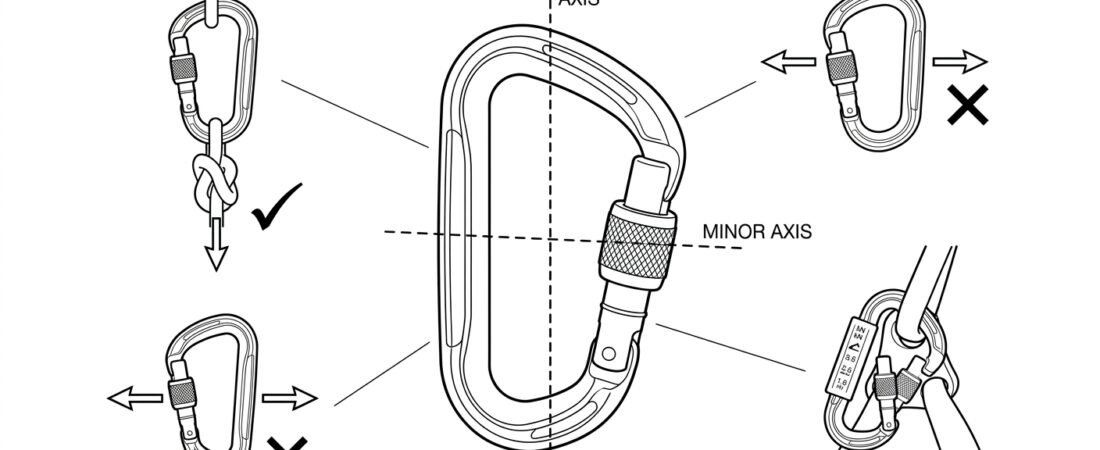
A connector is the smallest component in most rope-access and confined-space systems and the one most often loaded in a way it was never designed for. Every anchor, every lanyard, every descender and back-up device is attached through one, and the difference between a connector working at its rated strength and failing well below it usually comes down to two things: whether the gate is fully closed and locked, and whether the load is running along the spine. This note covers connector anatomy, the loading axes, and the specific field situations that quietly move load off the strong axis.
The parts of a connector, and why each one matters
Terminology matters here, because inspection criteria and manufacturer instructions are written in these terms.
- Spine (back): the solid, unbroken side of the frame. This is the load-bearing structure and the strongest part of the connector.
- Gate: the moving side. It closes the shape but contributes comparatively little strength; its main job is to keep the connector captive around whatever it is clipped to.
- Hinge (rivet or axle): the pivot at the bottom of the gate. Grit and corrosion here are a common cause of sluggish or incomplete gate closure.
- Nose and keeper: where the gate seats against the frame. Depending on design this is either a hooked nose with a notch, or a keyed/keylock nose designed to reduce snagging.
- Locking sleeve or mechanism: screw sleeve, or a two- or three-stage automatic mechanism. See connector locking systems compared for how these differ in practice.
- Basket: the wide, curved top of the connector where the load-bearing element should sit.
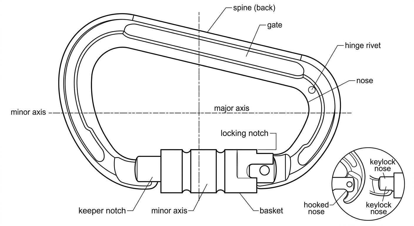
Connector anatomy: the spine carries the load, the gate only keeps the connector captive.
Connectors used in fall protection and work at height in Europe are placed on the market to EN 362 (connectors for fall protection), which defines classes by intended use — for example anchor connectors, basic connectors, screwgate connectors, terminal connectors for a specific harness attachment, and multi-use connectors. Mountaineering and climbing connectors are certified to a separate standard (EN 12275) with different assumptions about use. The class marking on a connector is not decoration: it tells you the application the manufacturer tested it for.
The major axis is the only axis the connector is built for
Rated strength is a directional figure. The major axis runs lengthways through the connector, from the basket at the top to the bottom of the frame, with the load pulling straight against the spine. This is the orientation in which the marked strength applies, and for most EN 362 connector classes the minimum major-axis strength required is 15 kN with the gate closed and locked.
Two other loading directions matter because they occur constantly on site:
- Minor axis (cross-loading): load pulling across the connector, gate to spine. Here the gate becomes a structural member, which it is not designed to be. Strength in this direction is substantially lower than the major-axis figure — typically a fraction of it, and manufacturers who mark a minor-axis value mark it separately for exactly this reason.
- Three-way loading: load applied at three points at once, for example when a connector is clipped through a harness attachment point, a lanyard eye, and something else, so the frame is being spread from the inside. This can push the gate open or bend the frame at loads well below the rated strength.
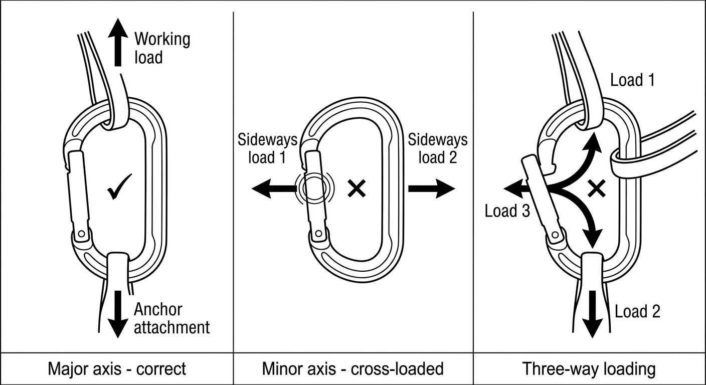
Rated strength applies only to major-axis loading; cross-loading and three-way loading both put load through the gate.
The practical rule is simple: one connector, one interface at each end, loaded along the spine. If you find yourself stacking three items into a single connector to save a component, the correct answer is normally a second connector, a ring, or a properly rated attachment plate.
Gate-open strength: the number nobody plans for
A connector with the gate held open is dramatically weaker than the same connector closed, because the load path through the frame is interrupted. Manufacturers commonly mark a separate gate-open value on the connector body, and it is a far smaller figure than the major-axis rating. Nothing in a working system should be able to hold the gate open — but several very ordinary situations do:
- Nose snag: the nose catches on a harness attachment bridge, an anchor eye, a rope, or a structural edge, holding the gate off its seat while looking closed at a glance.
- Gate pressed against structure: the connector lies flat against steelwork, a beam flange, or a concrete face, and pressure on the gate or sleeve opens the mechanism. This is the specific failure mode that manual screwgates suffer from when they are left partially threaded, and the reason gate orientation should be checked and the gate turned away from the surface.
- Sleeve interference: tape, ice, paint overspray, mud, or a rope running across the locking sleeve prevents it from returning fully. A gate that closes but does not lock is not a locked connector.
- Roll-out: the connector shifts on a wide or thick attachment — a large ring, a wide webbing loop, a scaffold tube — until the attachment is levering directly against the gate and can work its way out through the nose. Snap hooks with a keeper on the wrong-size anchor are especially prone to this.
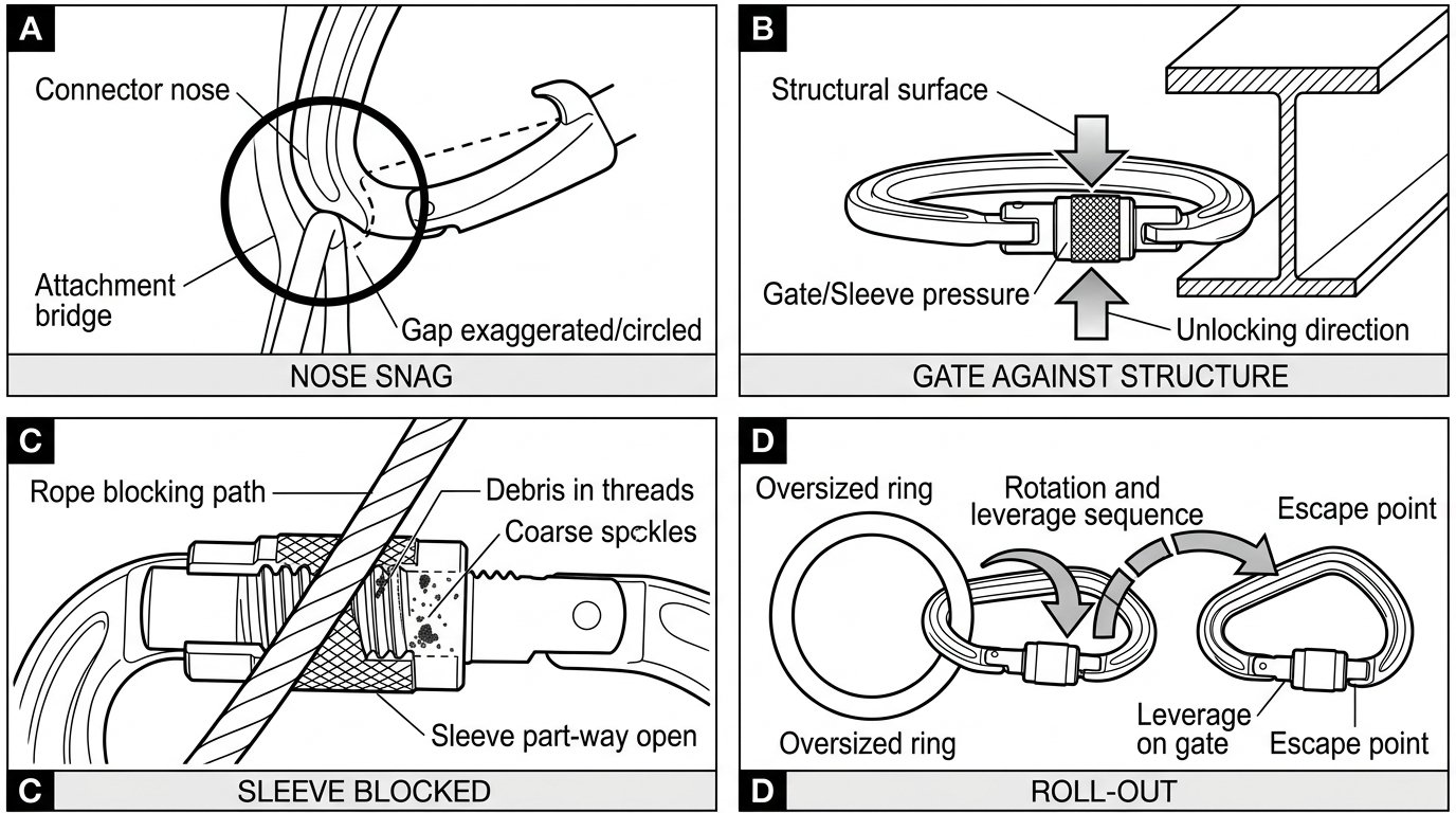
Four everyday ways a gate ends up open or unlocked while still looking closed.
Levering over an edge is a related problem. If a connector spans a rigid edge — a beam corner, the lip of a manhole, a plate edge — the frame can be bent across that edge rather than pulled along it. Position anchor connectors so the frame hangs clear, or use a connector shaped and rated for that anchor, as covered in connector shapes and where each belongs.
Keeping the connector aligned under load
Most cross-loading is not a mistake at the moment of clipping in; it happens later, when the system moves. A connector that starts out aligned rotates as the worker changes position, as a rope tensions, or as a descender or back-up device pivots. Design features exist specifically to stop this:
- Captive-eye connectors, where a narrowed lower section holds the harness attachment point or device hole in one place so the connector cannot rotate into a cross-load.
- Retaining pins or bars supplied with descenders and some devices, which keep the connector in the intended orientation in the device attachment hole.
- Directional keepers and captive bars on lanyard end connectors that limit how far the connector can slide along a wide attachment.
Two habits also help. First, avoid connecting a connector directly to another connector — two curved frames will roll against each other and load each other on the minor axis unpredictably. Use a sling, ring, or a proper attachment point between them. Second, check the fit before loading it: a connector should be able to seat and rotate freely in the intended orientation without the frame binding on the surrounding hardware. The field method for checking connector compatibility before you clip in sets out how to do that in a few seconds, and device-specific considerations are covered in the note on choosing a connector for a descender.
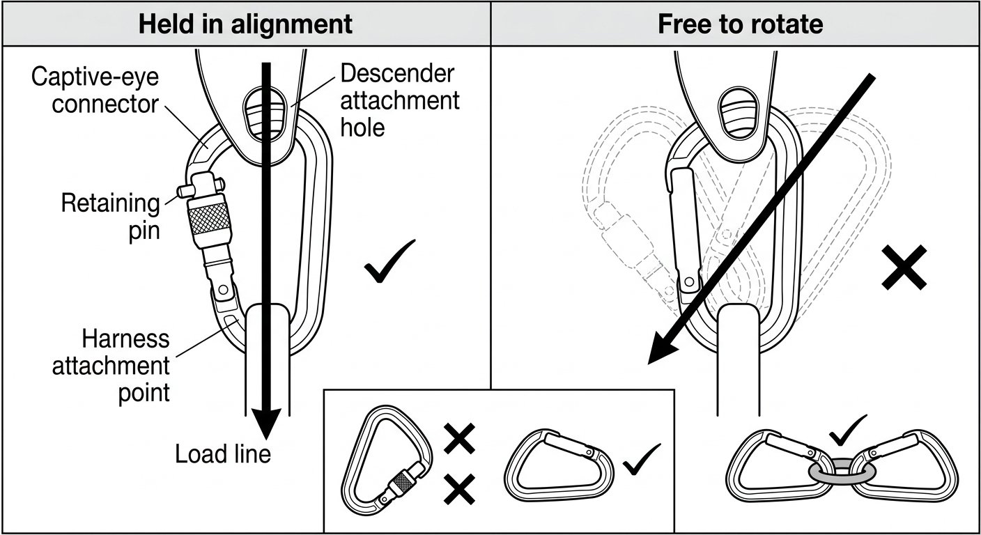
Captive eyes, retaining pins and an intermediate ring stop a connector rotating into a cross-load as the system moves.
Reading the markings
Everything you need to make a decision is usually engraved on the connector, and it is worth being able to read it at arm’s length:
- Manufacturer and model identification.
- Standard and class — for example EN 362 with a class letter indicating the intended application.
- Strength values in kN, normally the major-axis figure, with minor-axis and gate-open values marked separately where the manufacturer provides them. A pictogram of the loading direction usually accompanies each.
- Individual serial or batch number, used to link the connector to its inspection record.
- CE marking and, on many products, a symbol directing the user to the manufacturer’s instructions.
If markings have worn to the point where the class and strength can no longer be read, the connector cannot be verified for the application and should be withdrawn from service, regardless of its condition otherwise.
Pre-use checks that catch axis and gate problems
A connector check takes a few seconds and should be done every time the connector is put into a system, in addition to the periodic inspection required by the manufacturer’s instructions:
- Frame: no cracks, deep gouges, corrosion, or deformation. Any sign that the frame has been bent — a gate that no longer seats squarely is often the first symptom — is cause for withdrawal.
- Gate action: open it fully and let it go. It should snap closed cleanly, without hesitation or grinding.
- Lock: confirm the sleeve returns and locks by itself on an auto-lock, or is fully threaded down on a screwgate. Then press on the gate to confirm it will not open.
- Nose and keeper: check for a chipped or burred nose, or a bent keeper, which can hold the gate slightly open or cause snagging.
- Orientation in place: once clipped, look at where the load will run. Is the spine taking the pull? Is the gate turned away from any surface? Can the connector rotate into a cross-load as the worker moves?
Any connector that has taken a significant fall load or a heavy impact from a drop should be removed from service and referred to the manufacturer’s criteria, not returned to the kit on visual appearance alone.
The takeaway
A connector delivers its rated strength under one specific set of conditions: gate closed, gate locked, load along the major axis, and a single interface at each end. Every field problem in this note — snagged nose, gate against structure, roll-out, three-way loading, connector-on-connector — is a variation on losing one of those conditions. Building the habit of checking spine alignment and gate lock at the moment of clipping in, and choosing connectors with captive eyes or retaining pins where a system is going to move, removes most of them.
For the rest of this series, including harness attachment, device selection and entry procedure notes, see the rope access and confined space technique notes.
Frequently asked questions
What is the difference between the major and minor axis of a connector?
The major axis runs lengthways through the connector so that the load pulls straight against the spine, and this is the direction in which the marked strength applies. The minor axis runs across the frame from gate to spine, making the gate carry load it was not designed for. Strength across the minor axis is substantially lower, which is why manufacturers mark it separately where they provide a figure at all.
Why is gate-open strength so much lower than the rated strength?
With the gate closed and locked, load travels through a continuous frame. When the gate is held open, that load path is interrupted and the connector behaves like an open hook, so it deforms or fails at a fraction of its closed rating. Because nothing in a working system should hold a gate open, the practical priority is eliminating nose snags, gate contact with structure and blocked locking sleeves.
What is roll-out and how do I prevent it?
Roll-out is when a connector shifts on a wide or thick attachment — a large ring, thick webbing, a scaffold tube — until the attachment levers against the gate and works its way out past the nose. It is most common when the connector is undersized or the wrong shape for that anchor. Preventing it means matching connector size and shape to the anchor, using captive-eye connectors or keepers where the system will move, and checking the fit before loading it.
Can I clip one carabiner directly into another?
It should be avoided. Two curved frames roll against each other as the system moves and can end up loading each other across the minor axis, or pressing on a gate or locking sleeve. Use a sling, a rated ring, or a proper attachment point between them instead.
What markings should I be able to read on a connector?
Typically the manufacturer and model, the standard and class it was certified to, strength values in kN with pictograms showing the loading direction, an individual serial or batch number, and the CE marking. If the class and strength markings have worn away, the connector can no longer be verified for the application and should be withdrawn from service.
Does a connector need to be replaced after a fall?
A connector that has arrested a fall or taken a heavy impact — including a significant drop from height onto a hard surface — should be removed from service and assessed against the manufacturer’s criteria rather than returned to the kit on appearance alone. Frame deformation is not always visible, and a gate that no longer seats squarely is often the first sign of it.