
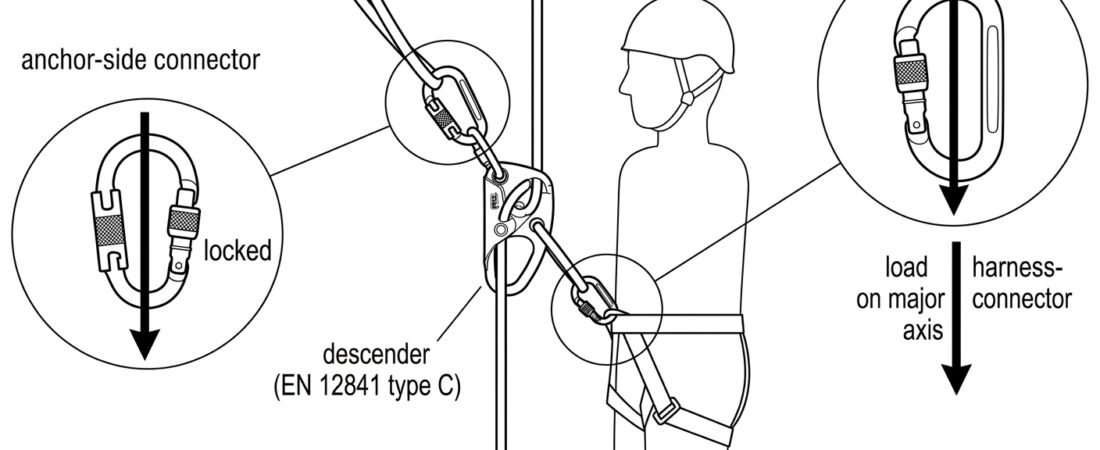
The connector between a descender and the harness is one of the smallest components in a rope access system and one of the least forgiving. It carries the operator’s full working load, it is handled dozens of times a shift, and it sits in a position where it can be rotated, pressed against a harness attachment point or loaded across its width without the operator noticing. Choosing the right connector for a descender – and confirming, before the first descent, that it actually fits the device it is attached to – is a short check that removes a large share of the practical failure modes seen in rope access work.
Two separate certifications, one working assembly
A descender and its connectors are tested and approved as separate products. Rope adjustment devices used for rope access are covered by EN 12841, which divides them into type A backup devices for the safety line, type B ascending devices and type C descending devices for the working line. Connectors are covered by EN 362, which sets out classes, strength requirements, gate performance and marking rules for connectors in personal fall protection systems.
Neither standard certifies the pairing. A descender marked to EN 12841 type C and a connector marked to EN 362 can both be fully compliant and still be a poor combination, because compatibility depends on geometry – the size and shape of the device’s attachment eye, the profile of the connector’s basket, the gate opening, and how much freedom the device has to rotate once loaded. Both manufacturers’ instructions for use apply simultaneously, and where a descender manufacturer specifies a connector type or shape for the attachment eye, that specification takes precedence over general preference.
Locking connectors at both ends – harness side and anchor side
A descender is attached with a locking connector at every point where it is part of the load path. That means the harness side and, where the device is rigged in a fixed or anchor-side configuration, the anchor side as well. Non-locking connectors have no place at either position. The reason is not theoretical: a descender in use is repeatedly pushed against the operator’s thigh, rope, harness webbing and structure, and an unlocked gate can be levered open by exactly this kind of incidental contact.
Beyond the requirement to lock, the choice of locking mechanism affects how reliably the connector stays locked. Screwgate connectors depend entirely on the operator screwing the sleeve down and on it not vibrating loose; automatic and triple-action mechanisms remove that dependency at the cost of slightly slower handling and more sensitivity to dirt and icing. The trade-offs are worked through in our comparison of connector locking systems, which is worth reading before standardising a mechanism across a team.
The harness side: ventral attachment and orientation
In most rope access configurations the descender hangs from the ventral attachment point of a sit harness or the ventral point of a full body harness certified to EN 361. The connector at this position spends its working life under continuous static load, so its orientation matters more than at any other point in the system.
The connector should sit with its spine bearing the load, the gate closed and locked, and the attachment point of the harness and the eye of the descender both seated in the basket rather than riding up towards the gate. A connector with a captive-eye or directional design is often preferred here, precisely because it prevents the connector from rotating into an unfavourable position between descents. EN 362 recognises this as a distinct problem and defines class T termination connectors as those designed to hold the load in a predetermined direction.
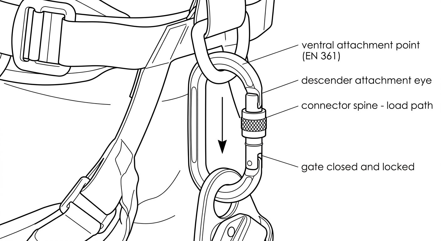
At the ventral position the connector should sit with the load running down its spine, both items seated in the basket and the gate closed and locked.
The anchor side: what the connector has to do differently
Where the descender is rigged at the anchor rather than at the harness, the connector performs a different job. It may be attached to an anchor sling, a ring, a steel eye or a structural member, and the shape of that interface decides which connector is appropriate. A wide steel bar or a large ring can put a small aluminium connector into a three-point loading condition; a narrow textile sling can allow a large connector to shift position under load.
Connectors intended for direct attachment to an anchor – EN 362 class A – are shaped and dimensioned for that use. Where a connector is being closed around structure, its gate opening has to be large enough to admit the member without forcing, and the connector has to be able to settle into a position where the load runs along its spine once tension comes on.
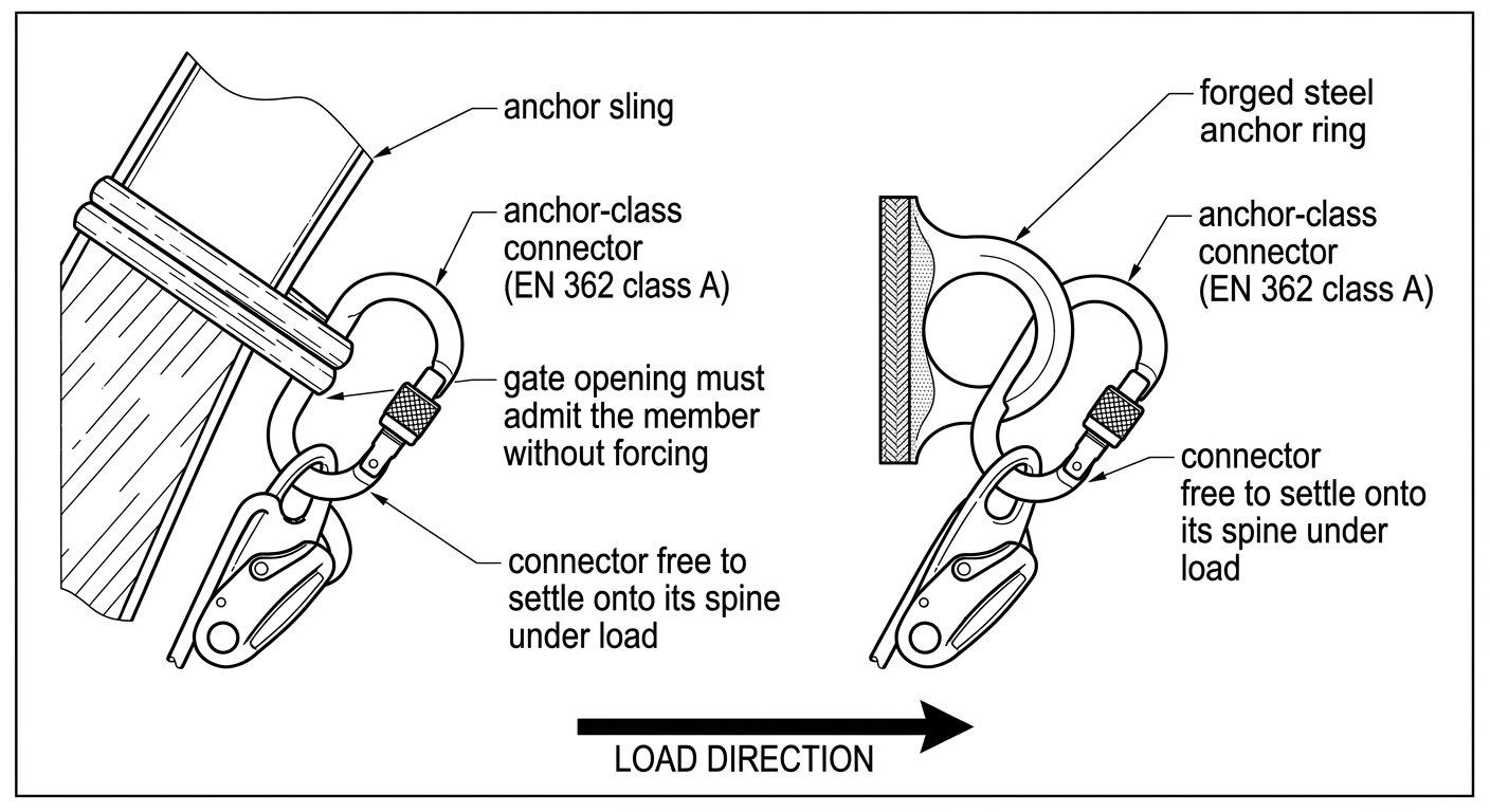
On the anchor side the interface geometry decides the connector: it must admit the anchor without forcing and settle onto its spine once loaded.
Gate clearance and pivot: the pre-use compatibility check
The compatibility check between connector and descender takes a few seconds and answers three questions.
- Does the gate open wide enough? The connector’s gate opening must admit the descender’s attachment eye without deforming the gate or requiring the eye to be forced past the nose. Forcing an eye through a gate that is marginally too small stresses the gate and nose – the weakest part of any connector – and can leave the eye jammed at the gate rather than seated in the basket.
- Can the device pivot freely? With the connector closed and locked, the descender should be able to rotate through its normal range of movement without any part of it bearing on the gate or the locking sleeve. A descender that presses on the gate as the operator changes position is applying load in exactly the direction the gate is not built to take.
- Does anything hold the connector out of alignment? Check that the harness attachment point, the descender eye and the connector spine can all line up. A stiff harness loop, a thick sling or a second connector sharing the same basket can hold the assembly at an angle where the load no longer runs down the spine.
This is a functional check, not a paperwork exercise. It should be repeated whenever a device is paired with a different connector, whenever a connector is replaced, and as part of the pre-use inspection at the start of a shift.
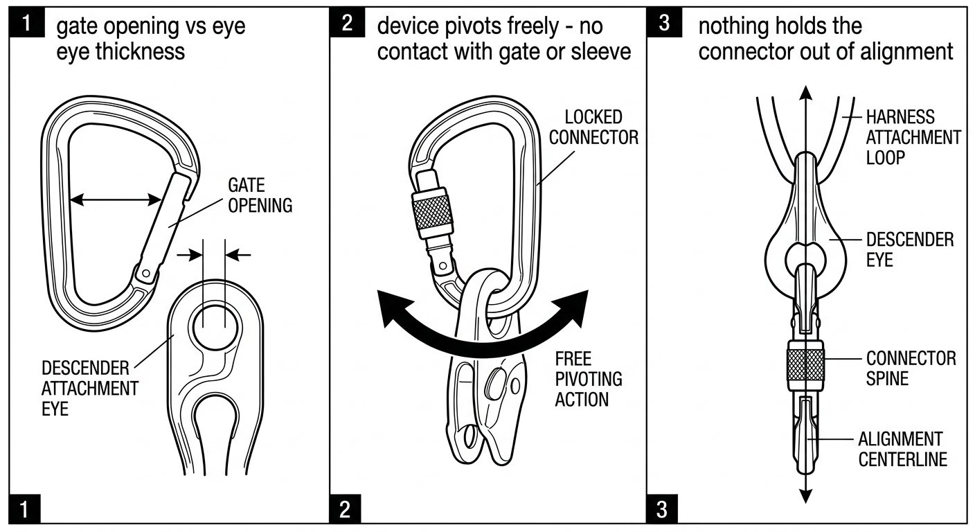
The pre-use check has three parts: gate opening large enough, device free to pivot without touching the gate, and nothing holding the assembly out of line.
Major-axis loading, cross-loading and gate-loading
The strength marked on a connector applies along its major axis – down the spine – with the gate closed and locked. Every other loading condition is outside that figure. Cross-loading, where the force runs across the short axis of the connector, and gate-loading, where the force is taken by the gate rather than the spine, both reduce the connector’s capacity substantially. These are not exotic conditions; they are among the most frequently observed rigging errors on site, and they arise from ordinary causes:
- The connector rotates in the harness attachment point as the operator moves, and comes to rest with the gate against the ventral loop.
- The descender’s attachment eye is too thick or too wide for the basket and rides up against the nose.
- Two items share one connector and force each other apart, spreading the load across the width.
- The connector is pressed against structure – a beam flange, a grating edge, an anchor plate – so that the gate takes the reaction load.
The countermeasures are equally ordinary: use a connector shaped for the attachment point, use directional or captive-eye connectors at the ventral position, keep one connector to one function, and physically check the alignment after weighting the system rather than only before.
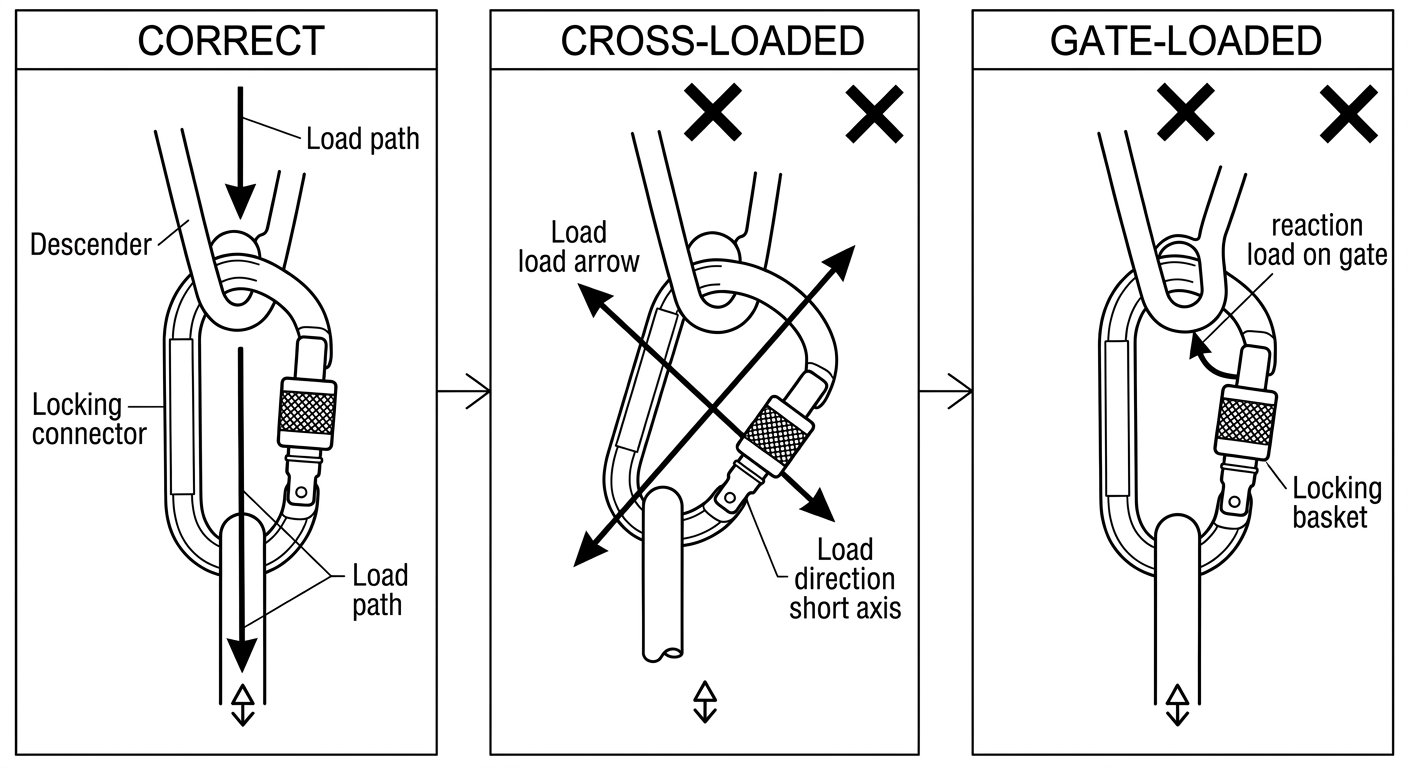
The marked strength of a connector applies along its spine with the gate locked; cross-loading and gate-loading fall outside that figure.
Selection summary
For a descender, choose a connector that is:
- Certified to EN 362 and of a class appropriate to the position – termination at the harness, anchor class where attached directly to structure.
- Self-locking or, where a screwgate is used, backed by a locking discipline the team actually follows.
- Dimensionally compatible with the specific descender: gate opening large enough for the attachment eye, basket deep enough for it to seat, and clearance for the device to pivot without touching the gate.
- Permitted by both manufacturers’ instructions for use, with any stated connector requirement from the descender manufacturer respected.
- Shaped and positioned so that under load it aligns on its major axis, without help from the operator.
Connector selection is one component of a wider set of rigging decisions – anchor choice, backup device on the safety line, and the work positioning arrangements covered by EN 358. The rest of the technique notes for rope access and confined space work are collected on the rope access and confined space hub page.
Frequently asked questions
Can a non-locking connector ever be used to attach a descender?
No. Every connector in the load path of a descender – harness side and anchor side – must be a locking connector. A descender in use is constantly pushed against the operator’s body, the rope and nearby structure, and that incidental contact is exactly what can lever an unlocked gate open.
If both the descender and the connector are CE certified, are they automatically compatible?
No. EN 12841 covers rope access adjustment devices and EN 362 covers connectors, but neither standard certifies the pairing. Compatibility depends on geometry – gate opening, basket shape, eye thickness and freedom to pivot – so it has to be checked with the two specific items in hand, and against both manufacturers’ instructions for use.
What is cross-loading, and why does it matter so much?
Cross-loading is when force runs across the short axis of a connector instead of down its spine. The strength marked on the connector applies to major-axis loading with the gate closed and locked, so any cross-loaded or gate-loaded condition falls outside that rating and reduces capacity substantially. It is one of the most common rigging errors seen in practice.
How do I check gate clearance before use?
Open the gate and confirm the descender’s attachment eye passes through without being forced past the nose or deforming the gate. Then close and lock the connector and move the descender through its normal range of rotation, checking that no part of it bears on the gate or the locking sleeve.
Should a screwgate or an automatic locking connector be used at the ventral attachment point?
Both can be compliant, but they fail differently. A screwgate depends on the operator closing the sleeve and on it not working loose, while automatic and triple-action mechanisms remove that dependency at the cost of slower handling and more sensitivity to dirt and ice. The choice should be made deliberately for the team and the environment rather than left to individual preference.
Why are directional or captive-eye connectors often recommended at the harness?
A connector at the ventral point is loaded continuously and tends to rotate as the operator moves, which can leave the gate bearing against the harness loop. Directional and captive-eye designs hold the connector in the intended orientation so that the load stays on the spine; EN 362 recognises this function as class T termination connectors.